Page 1152 of 1413
Connector ldentification and Wire Harness Routing
Hoator Sub-harneEs A
Hoator Sub-hameEs B
Connoctor or
Terminal
Numb€r of
CavitiesLocationConn6cts toNotog
c671
c672
c673
c674
c675
c676
c677
'lo
2
4
4
14
Under right side ot dash
Under right side of dash
Under right side of dash
Behind glove box
Behind glove box
Behind glove box
Behind middle of dash
Main wire harness (C404)
Main wire harness (C4o3)
Blower motor
Blower resistor
Recirculation control motot
A/C thermostat
Heater sub-harness B (C681)
connoctor 01
T6rminal
Number of
CavitioELocationConnocts toNotos
c681
c682
c683
c684
14
I
6
14
Behind middle of dash
Middle ol floor
Behind middle of dash
Behind middle of dash
Heater sub-harness A (C677)
Mode control motor
Heater Jan switch
Heater conttol Panel
HEATER SUB-HARI{ESS B
23-46
Page 1153 of 1413
Connector ldentification and Wire Harness Routing
UNDER-DASHFUSE/RELAY BOX
SRS Main Harness
Connector or
Terminal
Number ol
CavitiesLocationConnocts tol{otos
c801
c802
c803
c804
c805
c806
c807
2
4
o
18
2
I Behind dashboard lowet cover
J Under left side of dash
Under left side of dash
Middle of floor
Under left side of dash
Under right side of dash
Behind glove box
Under-dash f use/rclay box (C929)
Main wire haness 1C427)
Cable reel
SRS unit
Left dash sensor
Right dash sensor
Passenger's airbag assembly
G801Middle of floorBody ground, via SRS main
harness
23-47
Page 1171 of 1413
S€d8n:
,.-*-{.4rr-*Powgr door lock contrclunitDrivor's door lock actustorD ve/s door lock key cylind€l rwhchDdv6r's door lock switch
] Power window mrster switch)
Drivor's soat bolt swhch
Brx,4/vHr --E
lfr] ff;nj *",r *n
Irunk latch swhchf l8iler lighting connectorLicoruo pl.to lightsRioht I .L€-ft J nnst rrn gnr
Riohr ) .... .L€-ft J ran||gnr
Power anlonna mototHigh mo0nt bt'k6lightRear window dotoggor
] oo "onuo,unn
t,*----l ,_^
=,-"*- - f ABs contrclunh
@:
@:
E'
Ddvo/s door wir€ hemoss
ABS sub - hafn6s.
G5o2
otoa
.:
G702
23-65
Page 1176 of 1413
lgnition Switch
CAUTION:
a All SRS electdcal wiring harnessss aro covotod whh
yollow insulation.
a Botore disconnocting any part ot th6 SRS wiro har-
n6ss. connoct tha shon connoctor(t).
a Replac€ tho ontiro affected SRS hames! asllmbly It
it has an op6n circuit 01 damagod widng.
1. Remove the dashboard lower cover and knee bolster.
KNEE BOLSTERDASHBOARD LOWER COVER
Disconnect the 5-P connector flom the undsr-dash
fuse/relav box and the 7-P connector from the main
wire harness.
23-70
SRS MAIN HARI{ESS(Cov6red with Yollow inrulltiori)
J.Chsck tor continuity b€tween the terminals in each
switch position according to the table.
4. lf continuity checks do not agre€ with the tabl6,
reolace the €lectrical part of the switch lsee page
23-72t.
Terninal
P6itionBATtG1ST
--o
o-
I
Page 1177 of 1413

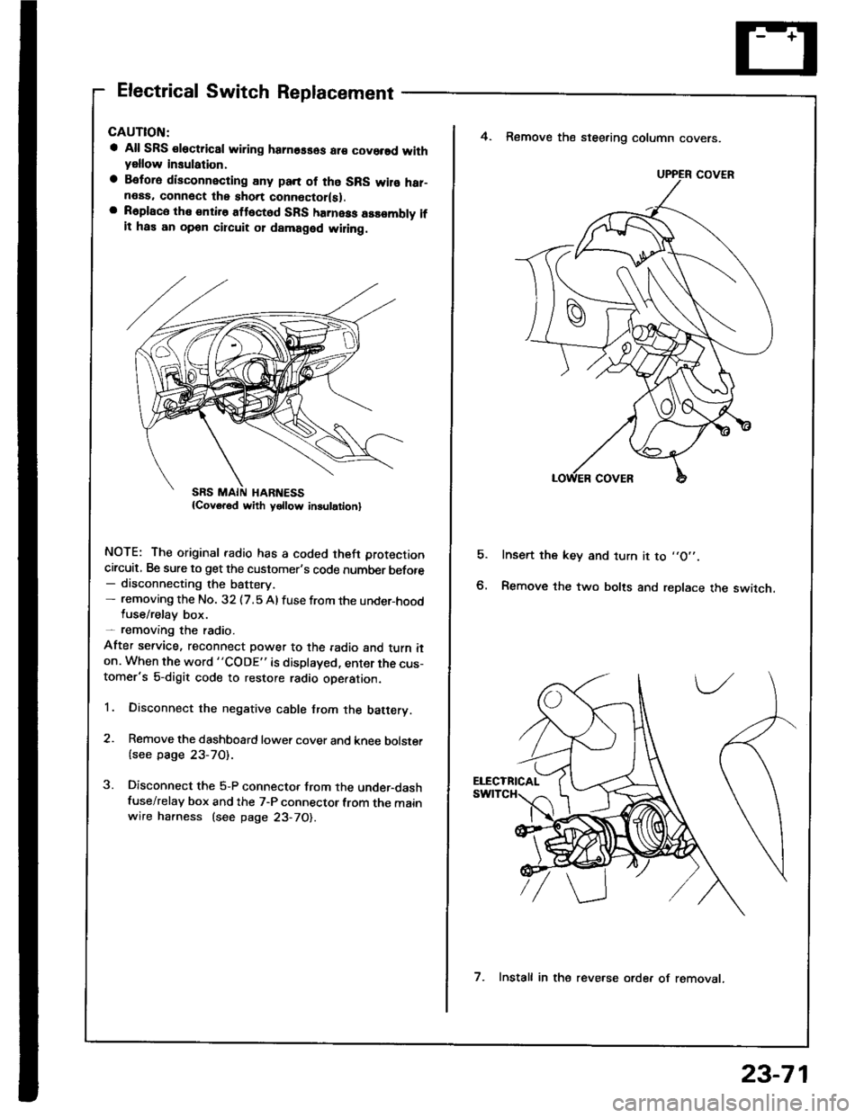
Electrical Switch Replacement
a All SRS €lectric8l wiring hamosses ar€ covorsd withyellow insulation,
a Befora disconnecting any pan of tho SRS wilo har-neas. connect the short connoctor(sl.a R6place the entire attect6d SFS harness assombly ifit has an opon circuit 01 damaged wiling.
NOTE: The original radio has a coded theft protection
circuit, Be sure to get the customer's code number before- disconnecting the battery.- removing the No. 32 (7.5 Al fuse from the under-hoodluse/relay box.- removang the radio.
After service, reconnect power to the radio and turn iton. When the word "CODE" is displayed, enter the cus-tomer's 5-digit code to restore radio ope.ation.
1. Disconnect the negative cable from the batery.
2. Remove the dashboard lower cover and knee bolster
{see page 23-70).
3. Disconnect the 5-P connector from the under-dashfuse/relay box and the 7-P connector from the mainwire harness (see page 23-70).
E
4. Remove the steering column covers.
Insert the key and turn it to ,,O',.
Remove the two bolts and replace the switch.
UPPER COVER
7. Install in the reve.se orde. of removat.
23-71
Page 1178 of 1413

lgnition Switch
Steering Lock Replacement
CAUTION:
a All SRS electrical wiring harnesses ale covsred with
yellow insulation.
a Belore disconnecting any parl ot the SRS wir€ hal-
ness, connecl the short connector{s).
a Replace the entire alfected SRS harness a$6mbly il
it has an open circuit or damaged wiring.
NOTE: The original radio has a coded thett protection
circuit. Be sure to get the customer's code number betore
- disconnecting the batterY.
- removing the No. 32 (7.5 A) fuse from the under-hood
fuse/relay box.- removing the radio.
After service, reconnect power to the radio and turn it
on. When the word "CODE" is displayed, enter the cus-
tomer's 5-digit code to restore radio operation.
1. Disconnect the negative cable from the battery.
2. Remove the dashboald lower cover and knee bolster
(see page 23-7'l ).
3. Disconnect the 5-P connector from the under-dash
fuse/relay box and the 7-P connector trom the main
wire harness {see page 23-71).
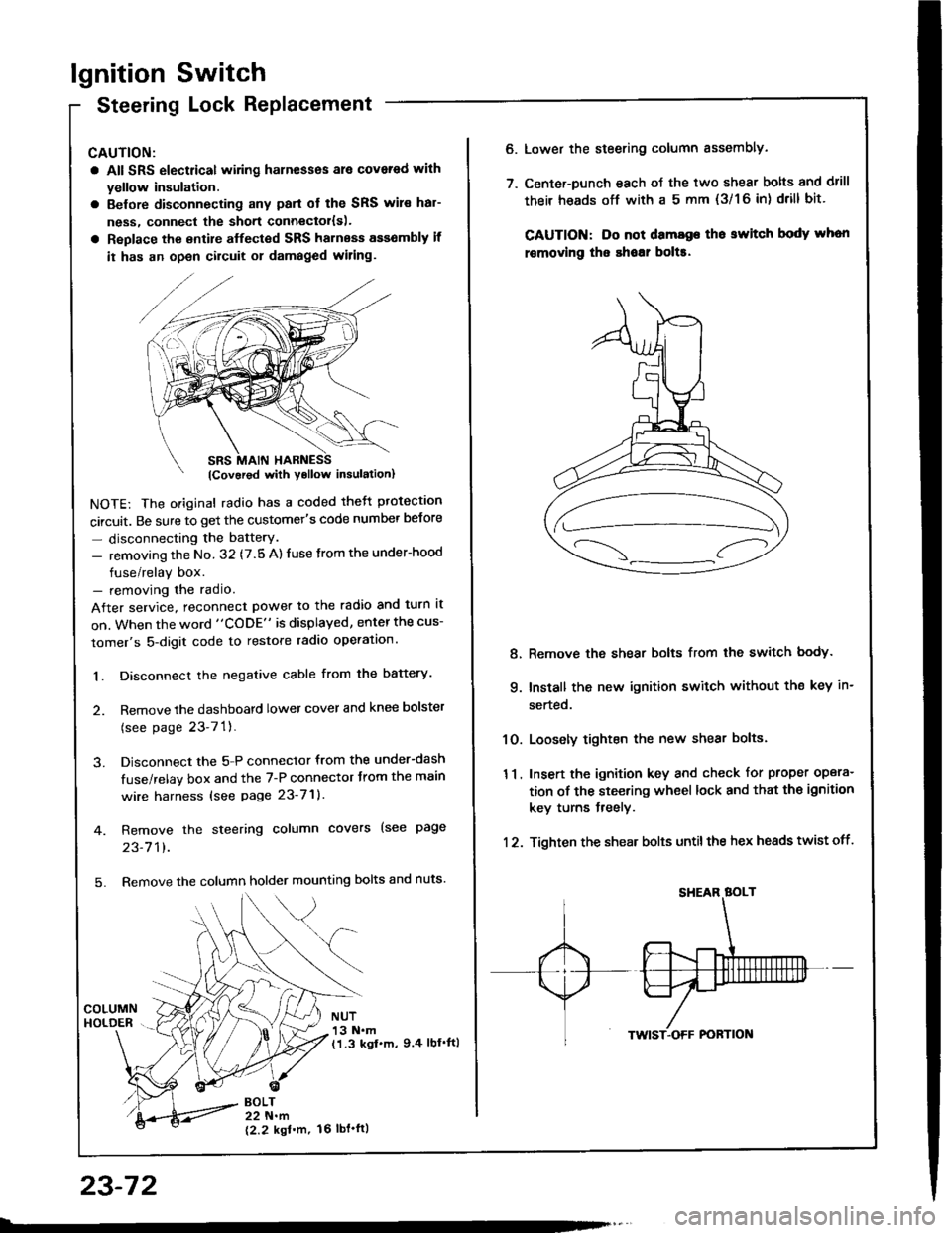
4. Remove the steering column covers (see page
23-711.
5. Remove the column holder mounting bolts and nuts'
BOLT22 N.m
12.2 kgl'm.
NUT13 N.m(1.3 kgf.m, 9.4 lbl'ftl
23-72
16 tbt.ftl
6. Lower the steering column sssembly.
7. Center-Dunch each oJ the two shear bolts and drill
their heads off with a 5 mm {3/1 6 in) drill bit'
CAUTION: Do not dama96 tho switch body whon
r€movlng the shoar bol$.
Remove the shear bolts from the switch body.
Install the new ignition switch without the key in-
serted.
Loosely tighten the new shear bolts.
Insert the ignition key and check for proper opera-
tion of the steering wheel lock and that th€ ignition
key turns freely.
Tighten the shear bolts untilthe hex heads twist off.
8.
q
10.
11.
12.
Page 1182 of 1413

Starting System
Startel Test
NOTE: The air temDerature must be between 59 8nd
10OoF (15 and 38oC) before testing.
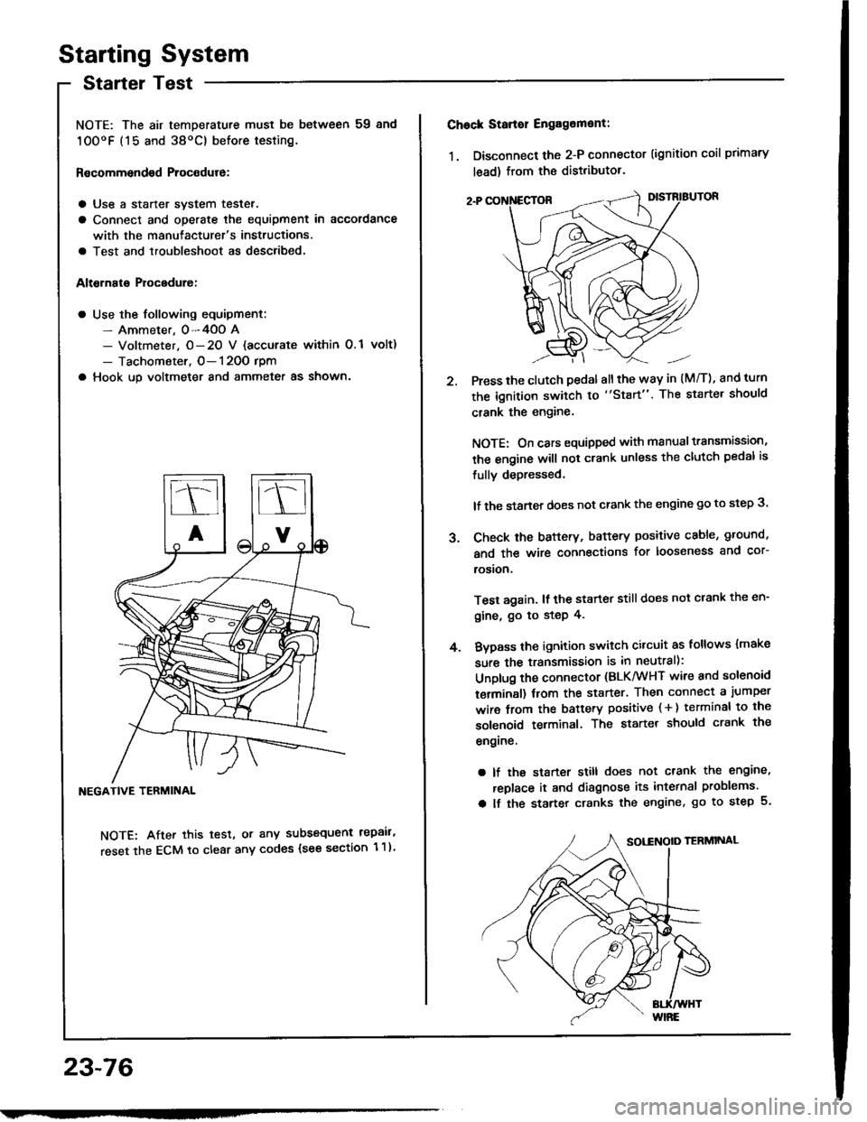
Recommendsd Procodure:
a Use a staner svstem tester.
a Connect and operate the equipment in accordance
with the manutacturer's instructions.
a Test and troubleshoot as described.
Altohato Procedure:
a Use the following equipment:- Ammeter. 0-4OO A- Voltmeter, O- 20 V {accurate within 0.1 volt)
- Tachometer, O- 120O rpm
a Hook up voltmeter and ammeter as shown'
NEGATIVE TERMINAL
NOTE: After this test, or any subsequent repair,
reset the ECM to clear any codes (see section 1 1)
23-76
2.
Chock Stan€r Engag6ment:
1. Disconnect the 2-P connector (ignition coil primary
lead) from the distributor.
Press the clutch pedal allthe way in (M/T), and turn
the ignition switch to "Start". The starter should
crank the engine.
NOTE: On cars equipped with manual transmission,
the engine will not crank unless the clutch pedal is
fully depressed.
lf the staner does not crank the engine go to step 3.
Check the baftery, battery positive cable, ground,
and the wire connections for looseness and cor-
rosion,
Test again. lf the starter still does not crank the en-
gine, go to step 4.
Bvpass the ignition switch citcuit as follows {make
sure the transmission is in neutral):
Unplug the connector (BLK/WHT wire and solenoid
terminsl) trom the starter. Then connect a jumper
wire from the battery positive ( + ) terminal to the
solenoid terminal. The starter should crank the
engrne.
a lf the starter still does not crank the engine,
replace it and diagnose its internal problems.
a lf the starter cranks the engine, go to step 5.
J.
4.
Page 1183 of 1413

5. Check lor 8n op€n in the BLKMHT wire circuit be-
tween the staner and ignition switch, and con-
nectors.
6. Check the ignition switch (see page 23-70).
7, On cars with automatic transmission, check the A/Tgear position switch (neutral position switchl and
connector. On cars with manualtransmission, check
the staner cut relay, clutch interlock switch, and
connectors.
NOTE: Check the No. 39 (5O A) fuse in the under-hood
fuse/relay box for the starter cut relay.
Check tor Woar and Damago:
The starter should crank the engine smoothly and stead-
ily. lf th€ startsr engages, but cranks the engine errati-
cally, remove it. Inspect the starter, drive gear, and
flywheel ring gesr for damage.
a Check the drive gear overunning clutch for binding
or slipping when the armature is rotated with the drivegear held. Replace the gesrs if damaged.
Check Cranking Voltago 8nd Current Draw:
Cranking voltage should be no less than 8.O volts.
Current draw should be no more than 360 amperes.
lf cranking voltag€ is too low, or current draw too high,
check for:
a Fully charged battery
a Open circuit in starter armature commutatot segments
a Starter armature dragging
a Shoned armature winding
a Excessive drag in engine
Chack Cranking rpm:
Engine spsod during cranking should be above 1O0 rpm.
lf spe6d is too low, ch€ck for:
a Loose battsry or starter teminals
a Excessively worn starter brushes
a Open circuit in commutator segments
a Dirty or damaged helical spline or drive gear
a Defective drive gear overrunning clutch
Chock StErtor Disongagomoni:
Press the clutch pedal allth€ way in (M/T), turn the ioni-
tion switch to "lll" and rolease to "11".
The starter drive gear should disengage from the tlywheel
ring gear. When you rolease the key.
lf the drive gear hangs up on th€ flywheel ring gear, check
for:
a Solenoid plunger and switch malfunction
a Dirty drive gear assembly or damaged overrunning
clutch
23-77