Page 1219 of 1413
Gauge Assembly
Component Location Index
CAUTION:
a All SRS electrical wiring harnosses are cov€rod withyellow insulation.
a Bofore disconnecting any prn ot th€ SRS wire har-ness, connect tho short connector(sl.a R€place th6 entirs affGcted SRS halne$ assembly ifit has an open circuit o? damaged wiring.
SRS MAIN HARNESS{Cov.r6d with yollow inrularionl
GAUGE ASSEMBLYGauge Location Index, page 23-114Indicator Location Index, page 23-1 14Terminal Location Index, page 23-114Bulb Location. page 23-'l 15Disassembly. page 23-1 19Removal, page 23-118
FUEL GAUGE SENDING UNtTTest, page 23'124Repfacemenr, page 23-124
VEHICLE SPEEO SENSOB IVSS}Test, page 23-120fnput Test. page 23-120Repfacement, page 23-122
PARKITTG BRAKE SWITCHTest, page 23-127
BRAKE FLUID LEVEL SWITCHTesr, page 23-127
EI{GINE OIL PBESSURE SWITCHTest, page 23-122
ENGINE COOLANT TEMPERATURE IECTI GAUGESENOING UNITTest, page 23-126
(C61'ios tho SBS indicator signal)
23-113
Page 1220 of 1413
Gauge Assembly
Gauge/lndicator/Terminal Location Index
CAUTIOI{:
a All SRS olectrical wiring harnessos aro covorod with
yellow insulation,
Belol€ disconnecting any part ot tho SRS wiro hat-
nesa. connoct the short connoctol(El.
Replaco th6 entire aff6cted SRS hamess sssombly lf
it has an open circuil or damagod widng.
co r{EcroR "c" (c558}
FUEL GAUGE:Gauge Test, page 23-123
Sending Unit Tost, page 23-124
23,-114
A/T GEAR POSIT|OIIDICATOR SYSTEISee pags 23-132
E GI[{E COOLAI{T TEIIPEFATURE IECTIc6uge TEst, p6g6 23-126Sending Unit Tsst, pago 23-126
TACHOMETER:Indicatos lOO rpm at20O puls€s per minul€of the ignition controlmodul€ llCM).
SPEEDOMETER:Indicates (60 mph 6i 1025 rpml or{60 km/h at 637 rem) of th€v€hicle spe6d sonsor lVSSl.
CoNNECTOR "8" (c5601
Bi ----------+ B16Cl ----+ClO
f',. /i)
)Y
-"b
\_./ \J \-___--
a1 -----> A5
Dl-------.>D13
col{]{ECTOR "D" (C5591
rtrF --
coNNECfOR "A" (C557)
Page 1224 of 1413
Gauge Assembly
Removal
CAUTION:
a All SRS electrical wiling harnesses ara cover6d with
yollow insulation.
a Eofore disconnecting any part ol the SRS wiro har-
n6ss, connoct lhe short connector(sl.
a Roplace tho entirs affocted SRS harneas assembly if
it has an open circuit 01 damaged wi.ing.
SBS MAIN HARI{ESS(Covor6d with Yollow in.ulationl
Remove the two screws lrom the instrument panel.
Remove the instrument panel.
NOTE: Remove the instrument panel careJully
without damaging the cliPs.
1.
2.
lcarrio. tho SRs indicolor 8ignal)
CLIPS
23-118
Tilt the steering wheel down with the tilt adjustment
tevet.
Remove the three mounting screws, and spread a
protective cloth on the steering column.
PROTECTIVE CLOTH
Pry the gauge assembly out, and disconnect allcon-
nectors from it.
GAUGE ASSEMBLY
Take out the gauge assembly as shown.o.
Page 1226 of 1413

Speedometer/Trip Meter/Odometer
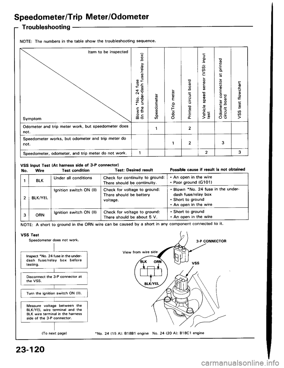
Troubleshooting
NOTE: The numbers in the table show the troubleshooting sequence.
Item to be inspected
Symptom
-9
;6+*c.r i.(D
zc*f
;59cd)=
E
a
6
E
'iF
o
(L
:lt)a
o
-9
>g
q)
qlv
E
'
E
oo
Odometer and trip meter wotk, but speedometer does
not.12
SDeedometer works, but odometer and trip meter do
nor,1
Speedometer. odometer, and trip meter do not work.
VSS Input Test (At ham€ss side of 3-P connector)
No. Wir6Tost conditionT€st: Desirsd resultPossible cause it result is not obtained
1BLKUnder all conditionsCheck for continuity to ground:
There should be continuity.
. An open in the wire. Poor ground (G1O1)
BLK/YEL
lgnition switch ON (ll)Check tor voltage to ground:
There should be battery
voltage.
Blown *No. 24 fuse in the unde.-
dash tus€/relay box
Short to ground
An open in the wire
ORNlgnition switch ON (ll)Check for voltage to ground:
There should be about 5 V.
. Shon to ground
. An open in the wire
NOTE: A short to ground in the
vSS Tost
Speedometer does not work.
ORN wire can be caused by a short in any component connected to lt.
3-P CONNECTOR
Inspect 'No. 24luse in the under-dash tuse/relay box beloretesting.
Turn the ignition switch ON lll).
Measure voltage between theBLK/YEL wire terminal and the8LK wire terminal in the harnessside of the 3-P connector.
{To next page)
23-120
24 (15 A): 81881 engine No. 24 {20 A): 818C1 engine
Page 1228 of 1413

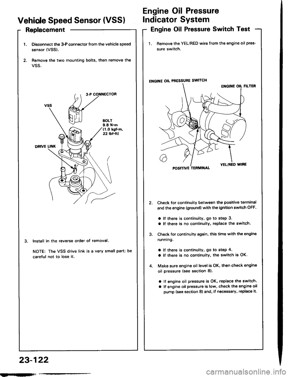
Replacement
Disconnect the 3-P connector trom the vehicle speed
sensor {VSS).
Remove ihe two mounting bolts, then remove the
VSS.
InstSll in the revsrse order of removal.
NOTE: The VSS drive link is a very small paru
caretul not to lose it.
Engine Oil Pressure
Vehide Speed Sensor (VSSIIndicator System
Engine Oil Pressure Switch Test
1. Remove the YEL/RED wile from the engine oil pres-
sure switch.
ENGI'{E OIL PRESSURE SWITCH
Check tor continuitv between the positive torminal
and the engine {gtound) with the ignhion swhch OFF.
a lf there is continuity, go to step 3.
a lf there is no continuity, replace the switch.
Check for continuity again, this time with th€ engine
runnrng.
a lf there is continuity, go to step 4,
a lf there is no continuity, the switch is OK.
Make sure engine oil level is OK, then check engin€
oil pressure (s€e section 8).
a lf engine oil pressure is OK, replace the switch'
a lf engine oil pressure is low, check the sngine oil
pump (see section 8) and, if necessary, replac€ it.
POSITIVE TERMII{AL
23-122
nlmlliitl
Page 1230 of 1413
Fuel Gauge
Sending Unit Test/Replacement
@ oo not lmoke while working on tho fuol
system. Kaop open flamos away from your wotk aroa.
1. Remove the rear seat (see section 2O).
2. Remove the protective cover and access panel lrom
the floor.
3. With the ignition switch OFF, disconnect the 3-P
connector from the fuel gauge sending unit.
4. Remove the tuel gauge s€nding unit.
5. Measure the resistance between the A and B termi-
nals at E (empty), 1/2 (half full) and F (full) by mov-
ing the tloat.
6. Check the change in resistance by moving the float
uo and down.
(
lf unable to obtain the above readings or it resistance
do€s not change, replace the fuelgauge sending unit.
Float PositionE
Resistance lO)105-11025.5-39.52-5
o
23-124
Page 1231 of 1413

Low FuelIndicator
IndicatorLight Test
Seat Belt Reminder
System
Seat Belt Switch Test
J.
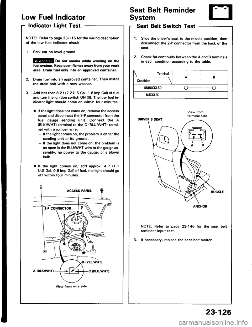
NOTE: Reter to page 23- 1 1 6 tor the wiring description
of the low fuel indicator circuit.
1. Park car on level ground.
@ oo not rmoko whil6 working on th€
fuol system, Keop op€n llamg3 awsy from your work
area. Drain fuel only into an approvod container,
Drain tuel into an 8pplov€d container. Then install
the drain bolt with a new washer.
Add less than 8.2 t (2.2 U.S.Gal, 1.8 lmp.Gal) of fuel
and turn the ignition switch ON (ll). The low fuel in-
dicator light should com€ on within lour minutes,
a lf the light does not come on, remove the access
Danel and disconnect the 3-P connector from the
fuel gauge sending unit, Connect the A
(BLKMHT) terminal to the C (BLU/WHT) termi-
nal with a iumper wir€.- lf the light comes on, the problem is either the
sending unit or its ground.- lf the light does not come on, the problem is
an open in the BLU/WHT wire to the gauge as-
sembly, no power to the gauge, or a blown
bulb.
a lf the light comes on, add approx. 4, {1.1
U.S.Gal, O.9lmp.Gal) ot tuel, the light should go
ofJ within four minutes.
3-P CONI{ECTOB
View lrom wire side
1.Slide the driver's seat to the middle position, then
disconnect the 2-P connector Jrom the back ot th€
sear.
Check for continuity between the A and B terminals
in each condition according to the table.
2.
NOTE: Befer to page 23-146 for the seat
reminder inout test.
3. lf necessary. replace the seat belt switch.
Terminal
C"** \AB
UNEUCKLEDo--o
BUCKLED
ANCHOR
23-125
Page 1235 of 1413

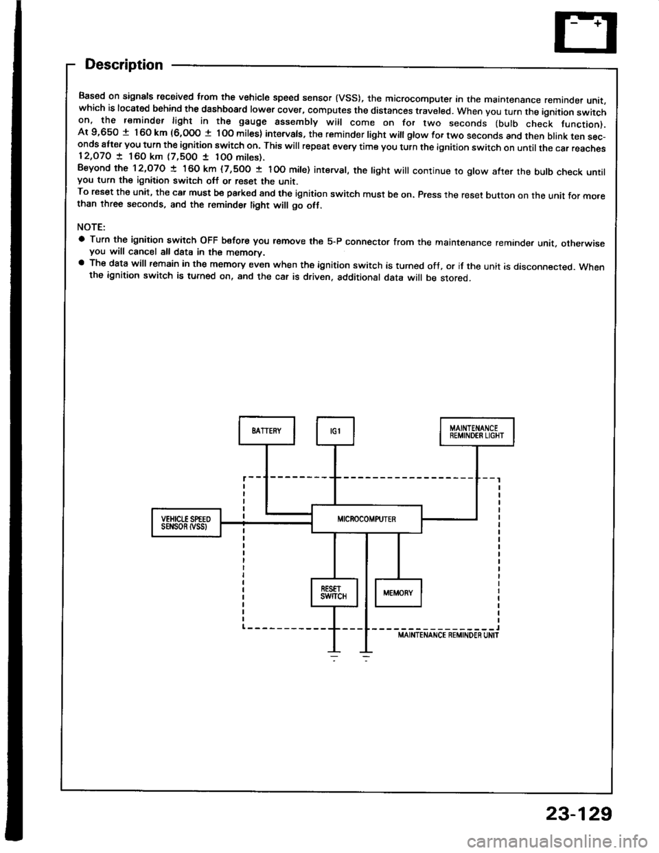
Description
Based on signals recaived trom the vehicle speed sensor (VSS), the microcomputer in the maintenance remande, unit,which is located behind the dashboard lower cover, computes the distances traveled. When you turn the ignition switchon, the reminder light in the gauge assembly will come on for two seconds (bulb check tunction).Ar 9,650 t 160 km (6,000 t lOo miles) intervals, the reminder light witl gtow for two seconds and then btank ten sec-onds att€r you turn the ignition switch on. This will repeat every time you turn the ignition switch on until the car reaches12,O7O ! 160 km (7,500 1 10O mites).Beyond the 12,O7O ! 160 km (7,500 t IOO mite) interval, the tight will continue ro gtow after the butb check untilyou turn the ignition switch off or reset the unit.To reset the unit, the car must be pa.ked and the ignition switch must be on. Press the reset button on the unit for mo.ethan three seconds, and the reminder tight will go otf.
NOTE:
a Turn the ignition switch OFF b€fore you r€move the 5-P connector from the maintenance reminder unit. otherwiseyou will cancel all data in the memorv.a The data will remain in the memory even when the ignition switch is turned ofJ, or if the unit is disconnected. Whenthe ignition switch is turned on, and the car is driven. additional data will be stored.
-----------------lMAINTENANCE REMINDEN UN|T
sEt{son tvss
23-129