Page 326 of 1413
#7 VACUUM HOSE
Troublclhooting
VACUUM PUMP/GAUGEA973X-O41-XXXXX
EVAP PTJBGE COI{TROLDIAPHRAGM VALVE
EVAPPUBGE CONTROL
Bl8Bl .noin.:YEL/BLK I+I
(-t
wirg aide
--\
EVAPR'RGE COI{TROLSOLENOID VALVE
(cont'd)
VALVE
YEL/BLK (+I
Disconn€ct #7 vacuum hose
trom the EVAP putgo control di'
aph.agm valve lon the EVAPcon-
t.ol canistor) and connoct a
vacuum gauge to tho hose.
Stsrt the €ngine and allow it toidls.NOTE: Engine coolant tempera-
ture must be b€low 163oF (73ocl
Oisconnect the 2P connegtor trom
the EVAP purge control solenoid
Mea suro voltago betw€enYEL/BLK {+) terminsl 6nd RED
l-) terminal.
Inapact vacuum hoa€ror.ring.l| OK, toolrc. EVAPpurgo conttol solenoidls ther6 battery voltage?
Moasule voltage botweenYEL/BLK {+) terminal bodYground.
(To pa96 1 1- 138)
(To page 1 'l -139)
11-137
Page 327 of 1413

(From page 1 1-137)
lTo page 1 1-'l39)
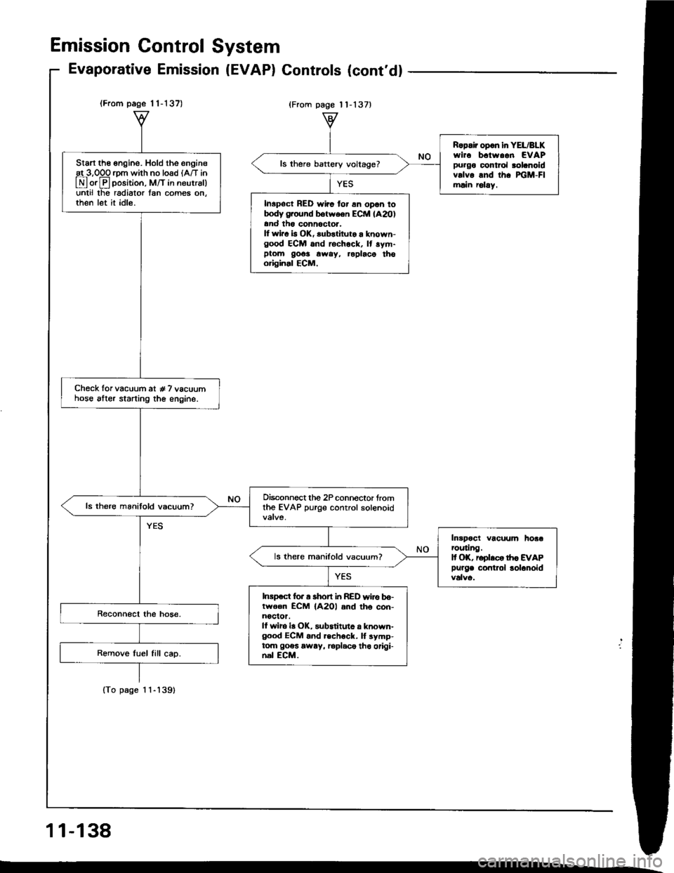
Start the engine. Hold the engineat 3,OOO rom with no load lA/T in
E orE position, M/T in neutrsl)unlil lhe radiator tan comes on.then let it idle.
Check lor vacuum at # 7 vacuumhose alter starting the engine.
Oisconnect the 2P connoctor fromthe EVAP purge control solenoid
Intpoct vacuum hoaarcuting.It OK, reolrco tr|c EVAP
Purge contlol lolanoid
ls there manifold vacuum?
Inrpoct for a short i|t RED wire bo-lwoen ECM {A2Ol and th6 con-noclor.ll wiro la OK, substituto a known-good ECM 6nd .echock. lf symp-tom goes away, loplace tho origi-nal ECM.
Ropair opon in YEL/BLKwirc b.tw..n EVAPpurgo control rolanoidvrlvo and th. xiM-Flmlin r6lay.
ls there baftery voltage?
Inspoct RED wirc for 6n opon totrody g.ound botween ECM lA20)and th6 conn6ctor.It wir. b OK, substiluto a known-good ECM and rochock, It sym-ptom 9o6s away, roplaco thooriginal ECM,
Emission Gontrol System
Evaporative Emission (EVAP) Gontrols (cont'd)
{From page 11-137}
11-138
Page 330 of 1413
Transaxle
Clutch
Manual Transmission ......................
Automatic Transmission ..................
Differential
Manual Transmission
81881 engine
818C1 engine
Automatic Transmission ...............
Driveshafts
12-1
13-1
14-1
15-1
15-9
15-19
16-1
Page 334 of 1413

Adjustment
NOTE:
a To check the clutch interlock switch and clutch
switch, see seclion 23.
a The clutch is selt-adjusting to compensate for wear.
CAUTION: It there is no clearanco between the mastel
cylinder piston and push lod. the releaso boaring is held
againsl the diaphragm spring, which can result in clutch
slippage 01 othel clutch problems.
Loosen locknut A, and back otf the clutch switch
{or adjusting bolt) until it no longer touches the clutch
pedal.
Loosen locknut C, and turn the push rod in or out
to get the specified stroke (@) and height (O) at the
clutch pedal.
Tighten locknut C.
Turn the clutch switch (or adjusting bolt) until it con-
tacts the clutch pedal.
Turn the clutch switch (or adjusting bolt) in 3/4 to
1 full turn further.
Tighten locknur A.
7. Loosen locknut B and the clutch interlock switch.
8. Measure the clearance between the tloor board and
clutch pedal with the clutch pedal tully depressed.
9. Release the clutch pedal 15-20 mm {O.59-O.79
in) from the fully depressed position and hold it there.
Adiust the position of the clutch interlock switch so
that the engine will start with the clutch pedal in this
oosition.
1 0. Turn clutch interlock switch 3/4 to 1 tull turn funher.
11. Tighten locknut B.
LOCKNUT B9.8 N.m (1.0 kgf.m, 7 lbf.ftl
CLUTCH INTERLOCKswtrcH
6.
1.
2.
ASSIST SPRING
-6ll
LOCKNUT Cl3 N.m l'l.3 kgf.m, 9
CLUTCH SWITCH{or AOJUSTING BOLTI
LOCKNUT A9.8 {N.ml (1.0 kgl.m, 7 lbt.ftl
(STROKE at PEDALI: 130-140 mm 15.12-5.51 in){TOTAL CLUTCH PEDAL FREE PLAY): 12-21 mm 10.47-0.83 inl including tho p.dal play I -lO mm 10.04-0.39 inl{CLUTCH PEDAL HEIGHTI: 164 mm (6.46 in} to tho lloot{CLUTCH PEDAL DISENGAGEMENT HEIGHTI: 83 mm 13.27 inl minimum to tho lloo.
PUSH ROD
CLUTCH MASTER CYLINDER
Clutch Pedalctutch Pedat I
[-],ll'"-"" f
| :;i:'":fff*tr#:?iff:".,*::,::". | .#::J:::
sb''�'�'""
| |
| "orr,O", It there is no clearanco between the master | ,. aoo""n locknut B and the clutch intertoct switcl. | |cylinder piston and push lod. the releaso boaring is held | | Iagainst the diaphragm spring, which can result in clutch | 8. Measure tne clearance between the floor board and I Islippage 01 othel clutch problems.
I
clutch pedal with the clutch pedal tully deeressed.
I I1. Loosen locknut A, and back otf the clutch switch | 9. Release the clutch pedal 15-2O mm (O.59-O.79 I I
{or adiusting boltl until it no longer touches the clutch I int trom ttre fully depressed position and hold it there. I I
, ::":"" rocknut c, and rurn the push rod in or out | iliiiliffi:l1l:J"'1"-:H"l:tJ:i"i#fT: I I
. il*:*j':"'-(@)andheisht(olatthe
|
,:.;:,nterrockswitch3/4torrurrturnturtner.
I tf
,
::
***r**''
.,".,u"**;
|
'-"'"'';*1,,0*.,.-,.,*,
I I
Page 339 of 1413

InspectionReplacement
Flywheel, Flywheel Bearing
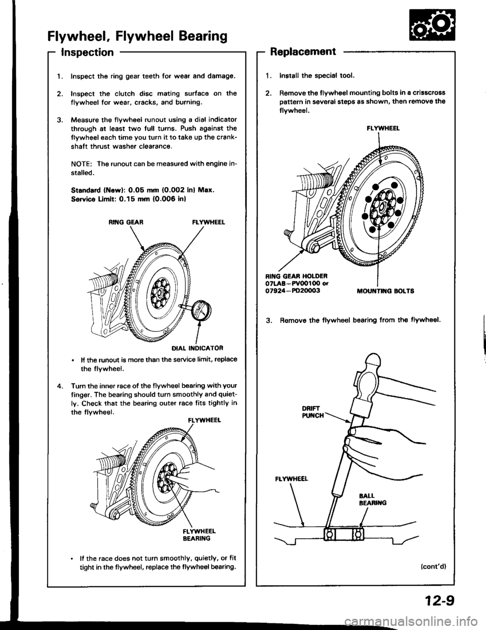
Inspect the ring gear teeth for wear and damage.
Inspect the clutch disc mating surface on the
flywheel fo. wear, cracks, and burning.
Measure the flywheel runout using a dial indicator
through at least two full tu.ns. Push against the
Ilywheel each time you turn it to take up the crank-
shaft thrust washe. clearance.
NOTE; The runout can be measu.ed with engine in-
stalled.
Standard (ttlervl: O.O5 mm (O.002 inl Max.
Service Limit: 0.15 mm 10.006 inl
RING GEABFLYWHEEL
DIAL II{DICATOR
It the runout is more than the service limit, leplace
the flvwheel.
Turn the inner race of the flywheel bearing with your
finger. The bearing should turn smoothly and quiet-
ly, Check that the bearing outer race fits tightly in
the flvwheel.
FLYWHEELBEARING
It the race does not turn smoothly, quietly, or fit
tight in the flywheel, replace the flywheel bearing.
Install the special tool.
Remov€ the flywhe€l mounting bolts in a criascross
pattern in several steps 8s shown, then remove the
tlywheel.
MOUI{TII{G BOLTS
3. Remov€ the flywheel bsaring from th€ tlywheel.
(cont'd)
FLYWHEEL
12-9
Page 345 of 1413

- Transmission Oil
NOTE: Check the oil with the engine OFF, and the car on
level ground.
1. Remove the oil filler plug, then check the level and
Maintenance
condition of the oil.
OIL FILLER PLUG44 N.m lia.5 kgf.m,
ORAIN PLUG$ N.m 14.0 kgf.m.29 lbf.fr)
33 tbtftlProper Level
2. The oil level must be up to the filler hole. lf it is
below the hole. add oil until it runs out, then rein-
stall rhe oil filler plug.
3. lf the transmission oil is dirty, remove the drain
plug and drain the oil.
4. Reinstall the drain plug with a new washer, and
refillthe transmission oil to the proper level.
NOTE: The drain plug washer should be replaced at
every oil change.
5 Reinstall the oil filler plug with a new washer.
OilCapacity
2.2 ( ''2.3 US.qt,1.9 lmp.qt) at oil chang€.
2-3 I l2.1Us.ql,2.0lmp.qtl at oyerhaul.
Use only SAE 10 w - 30 or '10 W - 40, API Service
SF or SG grade.
OIL FILLER PLUGa4 N.m l{.5 kgf.m, 33 lbf.ftl
Back-up Light Switch
Replacement
NOTE: To check the back-up light switch,
1. Disconnect the connector, then rem(
light switch connector trom the conn
2. Remove the back-up light switch.
BACX-UP LIGHT SWITCH25 N.m 12.5 kg[.m, 18 lbf.ftl
lnstall the new washer and the back-
Check the transmission oil level (see
Replace.
/itch, see section 23.
remove the back-up
]onnector clamp.
-up light switch.
) page 13-3).
Replace.
13-3
Page 347 of 1413
Removo tho clutch pip€ bracket and th€ slave cylin-
oer.
NOTE: Do not operate the clutch pedal once th€
slavg cvlinder has been r€moved.
R€move the three uppor transmission mounting
bolts 8nd lower staner motor mounting bolt.
STARTEBMOTOBMOUNNNGBOLT
MOUNNNGBOLTS
10. Remove the engine splash shield.
11. Disconnect the heated oxygen sensor (HO2S) con-
nector, lhsn rsmove the exhaust pipe A, and the
three way catalytic converter (B18Cl Engine).
HO2Sco NEctoRSELF.LOCK IIUTRopl.ce.
EXHAUSTPIPE A
THBEE WAYCATALYTICCONVEEIER1818C1 engin6)
SELF.LOCK NUTReplace.
13-5
Page 349 of 1413
19. Remove the clutch cover.
MOUNT/BRACKET
TRANSMISSION MOUNT
21.Place a transmission iack under the transmission
and a jack stand under the engine.
Remove the transmission mount.
23. Remove the rear mount bracket bolts and the trans-
mission mounting bolts.
24. Pull the transmission away from the engine until it
clears the mainshaft, then lower it on the transmis-
sion iack.
BRACKET
13-7