Page 619 of 1413

Troubleshooting
General Troubleshooting {cont'd}
Assist (excessively light steering) athigh speed.
Shock or vibration when wheel isturned to tull lock.
Wheelwill not return smoolhly.
ll the problem is not corrected byadjusting th6 rack g!ide. adjustthe front wheel alignment (see
section 18).
Check the rack guido proper ad'justment (see pago 17-21).
Check the rack guide tor properadjustment (ses psge 17-21).
Rack guide is adjusted prop€rly.
lf th€ problem is not correct€d byadiusting the rack guide, roplacethe gesrbox.Ch6ck the belt tor slip and adjustas nocessary (see page 17-20).
lf oither one or both of the cylin-der pip€ A and B is/are deformed,rsplace,
lf the cylinder pip6 A and B arenormal, remove the gearboxfrom th€ f.ame and mossure thepinion torqug on the gearbox.
It should be 0.7 - 1.2 N.m {7 - 12kgf.cm, 6 - 10 lbf.in) or belowwith the sleering rack in thestraight ahead driving position.
lf lhe measurem€nts are out ofspecilications. adjust the rackguid6.
ll ihe problem is not corrected byadjusting the rack guide, replaceihe gearbox.
17-12
Page 633 of 1413

Steering Wheel
Installation
Airbag installation
CAUTION:
. B€fore inrtalling the stooring wheel, align tho front
who6l3 etraight ahead.
. Bo sure to install the harness wires so that thGy are
not pinched or intorfsring with othor car parts.
. Do not roplace thc original stsoring wheel with any
othor design. since it will maks it impo$ibla to prop-
erly install the airbag. {Only use genuine HONDA
replscomont parts)
. After rols3embly. confirm thai the whoels are still
straight ahoad 8nd that steoring wheel spoke anglo
is correct. lf minor spoke anglo adiustment is noc€s-
srry, do so qnly by adlustment ol th€ tie-rods, not byromoving and repositioning the steering wh€€|.
@ contirm ihat the airbag assombly is
socurely attachsd to the stooring wheel; oth€rwise,
scvoro porsonal iniury could r€sult during airbag
doploym6nt.
1. Before installing the steering wheel, center the
cable reel.
Do this by tirst rotating the cable reel clockwise
until it stoos.
Then rotate it counterclockwise (approximately two
turnsl until:- The yellow gear tooth lines up with the mark on
the cover.- The arrow on the cable reel label points straight
UD.
YELI-OW GEAR
ALIGNMENT MARK
17-26
2. Install the steering wheel.
NOTE: Be sure the steering wheel shaft engages
the cable reel and canceling sleeve.
a9 N.m (5.0 ksf'm,36 lbf.ftl
Attach the cruise control sevresume switch€s con-nector to the steering wheel clip.
Connect ihe horn connector.
CRUISE CONTROLSET/NESUME SWITCHESCONNECTOR
Page 634 of 1413
5. Install the airbag assembly with new TORXo bolts.
TORXO BOLTS10 N.m {1.0 kgf'm.7 lbf ftl
Disconnect the short connector trom the airbag con-
nector.
Connect the airbag 3-P connector and cable reel 3-P
connector.
Attach the short connector on the access panel. and
install the access panel on the steering lower cover.
CABLE REEI-CONNECTOR
7.
YELLOW GEAR TOOTH
ALIGNMENT MARK
10.
Connect the battery positive terminal and th€n con-
nect the nsgative terminal.
After installing the sirbag assembly, confirm proper
system opera(on:
. Turn the ignition to ll: the instrum€nt pan6l SRS
indicator light should come on for about 6 sec-
onds and then go off,
. Confirm operation of horn buttons.
. Confirm oDeration of cruise control sevresume
switches.
a Turn the steering wheel countetclockwise and
make su.e the yellow gear tooth still lines up
with the alignment mark.
17-27
Page 670 of 1413

lnstallation
CAUTION; BG Glrc{ul not io bcnd or drm8go tho piping
whcn in3tllling tho gea.box.
1. Before installing the gearbox, slide the rack all the
way to right.
2. Pass the right side of the steering gearbox above
and through the right side of the rear beam.
3. Hold the steering gearbox and slide the rack all the
wav to the left.
4. Raise the left side of the steering gearbox above
and through the left side of the rear beam.
5. Install the pinion shaft grommet and insert the pin-
ion shaft up through the bulkhead.
NOTE: Align the tab on the pinion shaft grommet
with the slot in the valve bodv.
6. Install and tighten the gearbox mounting bolts.
NOTE: After installing the gearbox, check the air
hose connactions for interference with adjacent
pans.
58 N.m 15.9 kg[.m, $ lbl.ftl
TAA
38 N m 13.9 kgl.m, 28 lbt.ftl
17-63
YELLOW GEAR TOOTH
7.Center the steering rack within its stroke.
Make sure that the cable reel of the SRS is centered
as follows:
. Turn the steering wheel left approx. 150 degrees,
to check the cable reel position with indicator.
. lfthe cable reel is centered. the yellow gear tooth
lines up with the alignment mark on the cover.
. Return the steering wheel right approx. 150
degrees to position the steering wheel in the
straight ahead position.
ALIGNMEi'IT MARK
Slip the lower end of the steering joint onto the pin-
ion shaft (line up the bolt hole with the groove
around the shaft), and tighten the lower bolt.
NOTE:
. Connect the steering shaft and pinion with the
cable reel and steering rack centered.
. Be sure that the lower steering ioint bolt is se-
curely in the groove in the steering gearbox pin-
ion.
. lf the steering wheel and rack are not centeted,
reposition the serralions at lower end of the
steering joint.
(cont'dl
22 N.m 12.2 kgi.m, 16lbf.ftlLOWER BOLT
Page 1379 of 1413

Supplemental Restraint System (SRS)
Steerin g-related Precautions
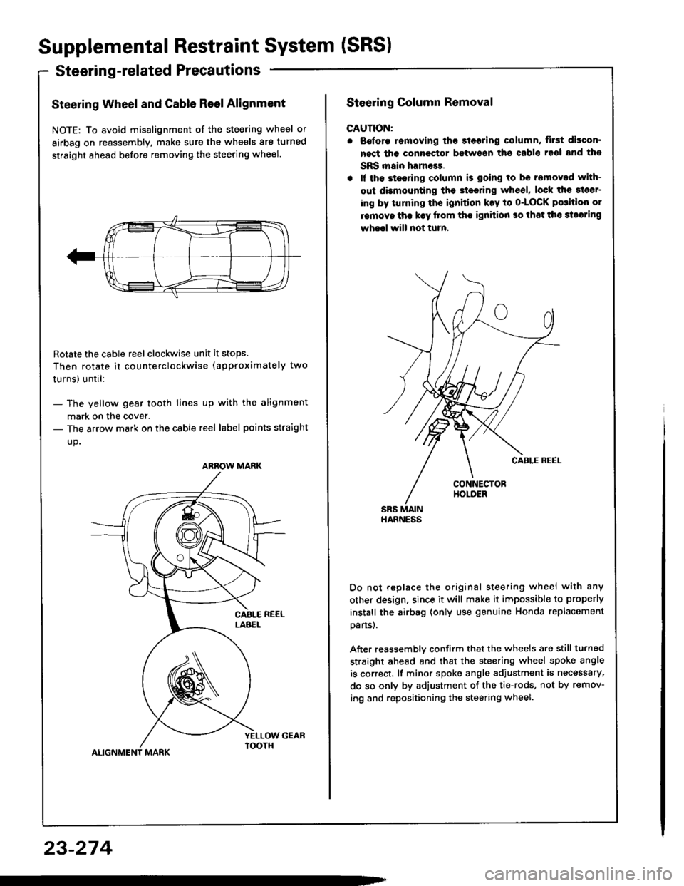
Steering Wheel and Cable Reel Alignment
NOTE: To avoid misalignment of the steering wheel or
airbag on reassembly, make sure the wheels are turned
straight ahead before removing the steering wheel.
Rotate the cable reel clockwise unit it stops.
Then rotate it co u nterclockwise (approximately two
turnsl until:
- The yellow gear tooth lines up with the alignment
mark on the cover.- The arrow mark on the cable reel label points straight
up.
ALIGNMENT MARK
ARROW MARK
23-274
Steering Column Removal
CAUTION:
. Bofore romoving tho 3l6oring column, first discon'
nect tha connector between ths cablo 16ol snd tho
SRS main harness.
. lf th6 stssring column is going to be removed with-
out dbmounting the stesring wh6el, lock the sl6sr-
ing by turning th€ ignition k.y to o-LOCK po3ition or
removo tha k€y llom ths ignilion so that th6 3loaring
wheel will not turn.
Do not replace the original steering wheei with any
other design, since it will make it impossible to properly
instsll the airbag (only use genuine Honda replacement
oans).
After reassemblv confirm that the wheels are still turned
straight ahead and that the steering wheel spoke angle
is correct, lf minor spoke angle adjustment is necessary,
do so only by adjustment of the tie-rods, not by remov-
ing and repositioning the steering wheel.
Page 1408 of 1413

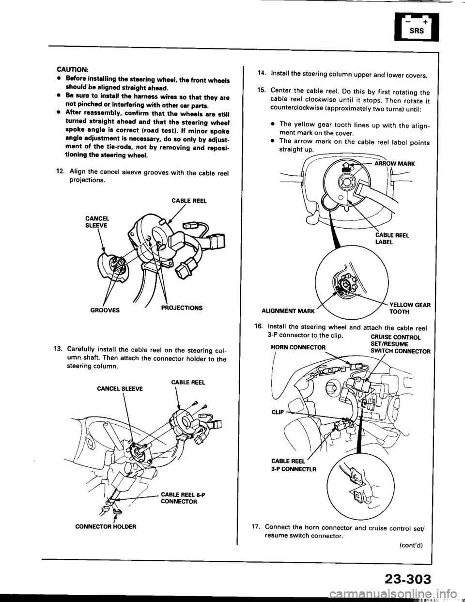
GAUTION:
o Eatora instdling tho steoring whosl, lha front whaelslhould bo alignod straight !ho!d.. Bc auro to imtalt tho hrrnass wiros so that th6y !16not pinchod or intsrt6ring with othor crr parts.. Aftor rsassambly. conlirm that tho whods lre 3tillturnad straight ahead and lh.t the steering wheolrpoko angle is corrsct {rosd tesi}. lf mino. spok€angl6 adiustmont is necols!ry, do 30 only by ldiust_mgnt ol tho tio-rod9. not by removing and rgposi-tioning tho rteering whoel.
12. Align th€ cancel sleeve grooves with the cable reelprojections.
Carefully install th€ cable reel on the steering col-umn shaft. Then attach the connector holder to thesteering column.
CABLE REEL
CABI.I REEL
CONNECTOR HOLDER't7.
23-303
14.
t5.
Installthe steering column upper ano tower covers.
Center the cable reel. Do this by first rotating thecable reel clockwise until it stops. Then rotate itcounterclockwise (approximately two turns) until:
. The yellow gear tooth lines up with the align-ment mark on the cover.a The arrow mark on the cable reel label Dointsstraight up.
ABROW MARK
ALIGNMENT MARK
16. Install the steering wheel and3-P connector to the clip.
HORN CONNECTOR
YELLOW GEARTOOTH
attach the cable reel
CRUISE CONTROLSET/RESUME
Connect the horn connector and cruise control sevresume switch connector.
(cont'd)