Page 1261 of 1413
Gircuit Diagram (Canadal
BATTERY
G"*
UNOER_HOOD FUSEiRETAY 8OX
coMBrNAtor{ rcHrswnc
-il w
| '.=r" I
ll'L I I
I I *o\." l-'li' ;- ;j
I LI
"- r.r-,9 "orr
I
d "
L
RED/BLU REO/}VHT RED,ll
I UNDEN-DASH II FUSEiIEI,AY 8OX I
tl
L-J
t'GRN
/d\BATtG2\9-l
rGNrTrot{swITcH
No.2lfl0A)\I
No.l9|l04]Jm.tr (
t10A) ttt
I
No.l6{7.54}
tl
i,"#
llrrff li'rrt,
RED/GRtIIBLU REOr'TVHTINED/B
V
WHTTYEL
. DASH LGHTS BRIGHTNESSCOI{TROLLER. DASH I-IGHTS. PARKING I-GHIS. TAII,LIGHTS. UCENSE N"AT€ LIGI{TS
I a-rneonru jllA/Vr l"o I f# wxrintoRED/GRI{ +\{H I
DAYTIME RUNNINGUGI{TS RESISTOR
IRED/GRN
Hr I r-01651,1/) | l55W)HIt85W)LOt55Wl
HIGH BEAMINOICATORUGHTfl.4W
I
RIGHTHEADLIGHTPARKIIIGBRAKEsw{TcH
23-155
Page 1263 of 1413

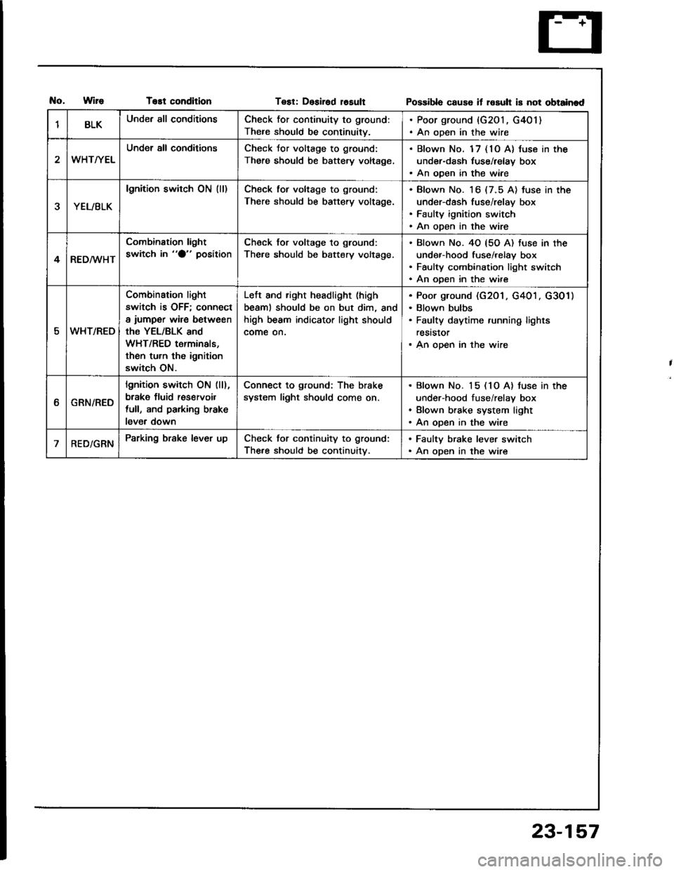
T€st conditionTest: Desirad losultPossibla cause if rosult is not obtainad
1BLKUnder all conditionsCheck for continuity to ground:
There should be continuity.
. Poor ground {G201, G401). An open in the wire
WHT/YEL
Under all conditionsCheck Jor voltage to ground:
There should be battery voltage.
. Blown No. 1 7 { 10 A} luse in the
under-dash tuse/relay box. An ooen in the wiae
YEL/BLK
lgnition switch ON (ll)Check tor voltage to ground:
There should be battery voltage.
Blown No. 16 (7.5 A) tuse in the
under-dash fuse/relay box
Faulty ignition switch
An open in the wire
4RED/WHT
Combination light
switch in "O" positionCheck for voltage to ground:
The.e should be battery voltage.
Blown No. 40 {5O A) fuse in the
under-hood fuse/relay box
Faulty combination light switch
An ooen in the wire
5WHT/REO
Combination light
switch is OFF; connect
a iumper wire between
the YEL/BLK and
WHT/RED terminals,
then turn th6 ignition
switch ON.
Left and right headlight (high
beaml should be on but dim, and
high beam indicator light should
come on.
Poor ground (G201 . G401 . G301)
Blown bulbs
Faulty daytime running lights
reststor
An open in the wire
ttGRN/RED
lgnition switch ON (ll),
brake fluid res€rvoil
full, and parking brake
lever down
Connect to ground: The brake
system light should come on.
Blown No. 15 (1O A) tuse in the
under-hood fuse/relay box
Blown brake system light
An open in the wire
RED/GRNParking brake lever upCheck for continuity to ground:
The.e should be continuitv.
. Faulty brake lever switch. An open in the wire
23-157
Page 1267 of 1413
Headlight
Description
The low beam lights are proiector-type lights which are more compact while maintaining sufficient brightness. Bundling
the light rays reduces stray light and yields a spotlight-effect which improves visibility during night or foul weather driving.
For easier aiming, the headlights are equipped with vertical and horizontal gauges.
NOTE: As the oute. lenses are made oI a resin material, don't cover the headlights when they a.e turned on.
OUTER LENScoNvEx LEI{SSUB-REFLECTORsEcoND FOCUSINTERRUPTER PLATEREFLECTOBFIRST FOCUSBULB
23-161
Page 1268 of 1413

Headlight
Adjustment
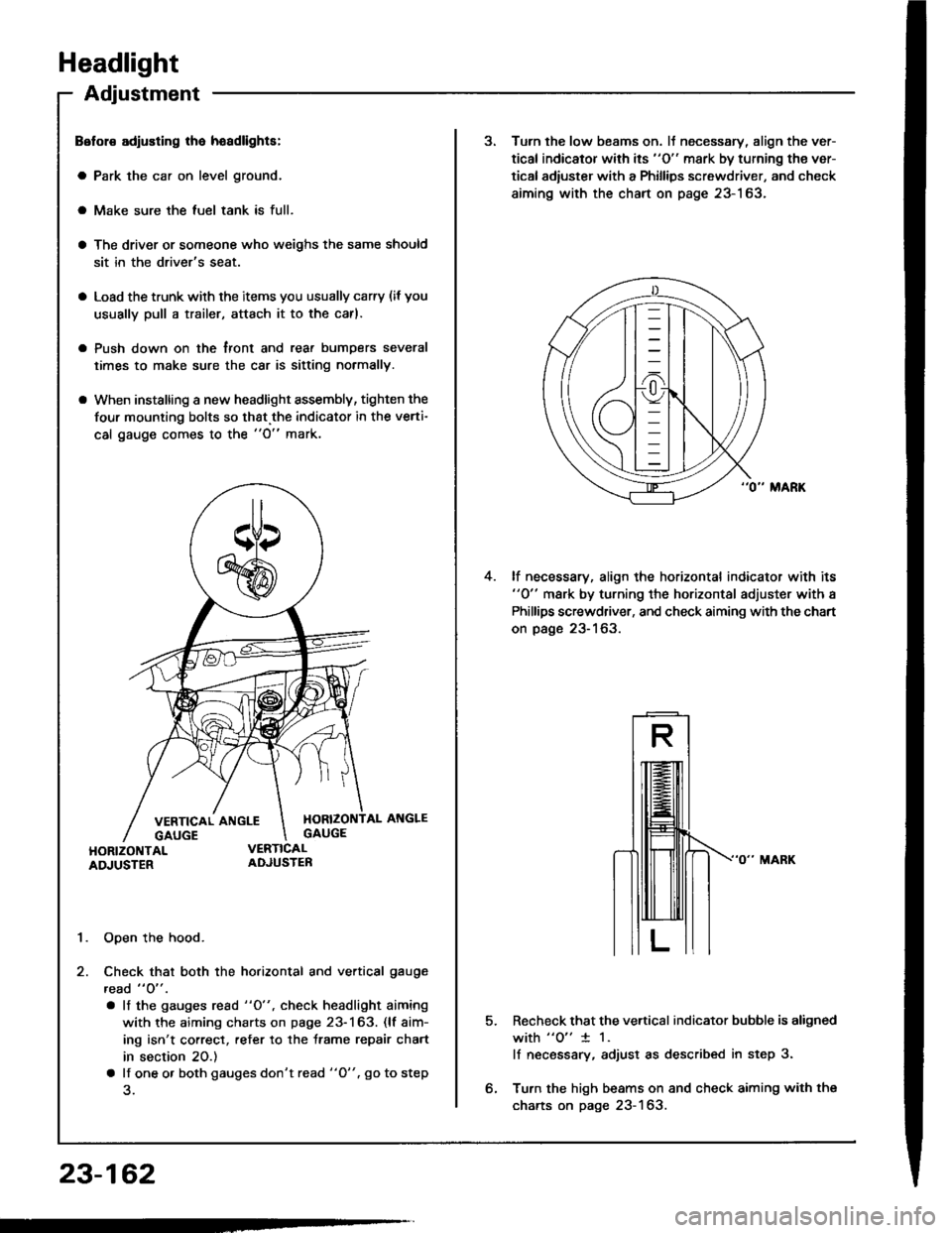
Belol€ adiusting lha hoadlights:
a Park the car on level ground.
a Make sure the luel tank is full.
a The driver or someone who weighs the same should
sit in the driver's seat.
a Load the trunk with the items you usually carry (if you
usually pull a trailer, attach it to the carl.
a Push down on the tront and rear bumDers several
times to make sure the car is sitting normally.
a When installing a new headlight assembly, tighten the
four mounting bolts so that.the indicator in the verti-
cal gauge comes to the "O" mark.
1. Open the hood.
2. Check that both the horizontal and vertical gauge
read " O" .
. lf the gauges rcad "O", check headlight aiming
with the aiming charts on page 23-163. (lf aim-
ing isn't correct, refer to the trame repair chart
in section 20.)
a lf one o. both gauges don't read "O". go to step
23-162
3. Turn the low beams on. lJ necessary, align the ver-
tical indicator with its "O" mark by turning the ver-
tical adiuster with a Phillips screwdriver, and check
aiming with the chart on page 23-163.
lf necessary, align the horizontal indicator with its"0" mark by turning the horizontal adjuster with a
Phillips screwdriver, and check aiming with the chart
on page 23-163.
4.
5.Recheck that the vertical indicator bubble is aligned
with "o" 1 1.
lf necsssary, adjust as described in step 3.
Turn the high beams on and check aiming with the
charts on page 23-163.
Page 1269 of 1413
Measurements (Standardl:
A: 9 fi 10 in (3000 mm)
B: 23 in (585 mm)
C: 46.1 in (1170 mml
D: 33.5 in (85O mm)
E; 1.2 in {31 mm}
Headlight Aiming
Low beam:High besm:
HEADLIGHTLOW BEAMCEt{TER
FLOOR
HEADLIGHTHIGH BEAM
FLOOR
CAUTION: Th6 out6r lonses get very hot when tho hoadlights are on; do not cover them.
23-163
Page 1270 of 1413
Headlight
Headlight Replacement
1. Remove the front bumoer.
Remove the mounting bolts, then pullout the head-
light, and disconnect the connectors from it.
Afte. replacement. the horizontal and vertical aim-ing must be checked using conventional methods,
Use the aiming charts on page 23-163.
Bulb Replacement
CAUTION:
a Halogon headlights can bocomo voly hot in usa; do
not touc$ them or tho attaching hardware imm6diatoly
arter they hava been lurnod off,a Do not try to roplace or cl6an the headlights with thelights on.
I . Oisconnect the 2-P connector(s) from the headlight.
coNlrtEcToR
2. Turn the bulb(s) counterclockwise and remove the
bulb(s).
FRONT BUMP€R
HEADLIGHT
23-164
Page 1277 of 1413

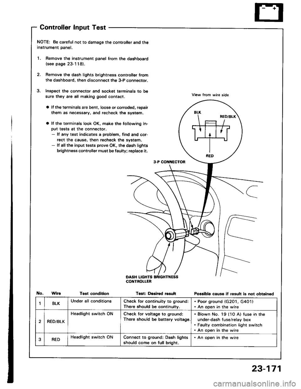
Controller Input Test
NOTE: 8e careful not to damage the controller and the
instrument panal.
1. Remove the instrument panel lrom the dsshboard
{see page 23-1181.
2. Remove the dash lights b.ightness controller {rom
the dashboard. then disconnect the 3-P connector.
Inspect the connector and socket terminals to be
sure they are all making good contact.
a lf the terminals are bent. loose o. corroded, repsir
them as necessary, and recheck the system.
a It the terminals look OK, make the tollowing in-
Dut tests at the connector.- lf any test indicates a problem, find and cor-
rect the cause, then recheck the system.- lf all the input tests prove OK, the dash lights
brightness controller must be faulty; replace it.
View from whe side
Possible causo it resull is not obtained
3-P CON[{ECTOR
OASH LIGHTSCOI{TROLIER
WireTost conditionTogt: Dasired resuh
1BLKUnder all conditionsCheck for continuity to ground:
There should be continuitv.
. Poor ground (G20 l , G4O1). An open in the wire
RED/BLK
Headlight switch ONCheck Jor voltage to ground:
There should be battery voltage.
Blown No. 19 (1O A) tuse in the
under-dash fuse/relay box
Faulty combination light switch
An open in the wire
aREDHeadlight switch ONConnect to ground: Dash lights
should come on full bright.
. An open in the wire
23-171
Page 1320 of 1413

Moonroof
Function Test
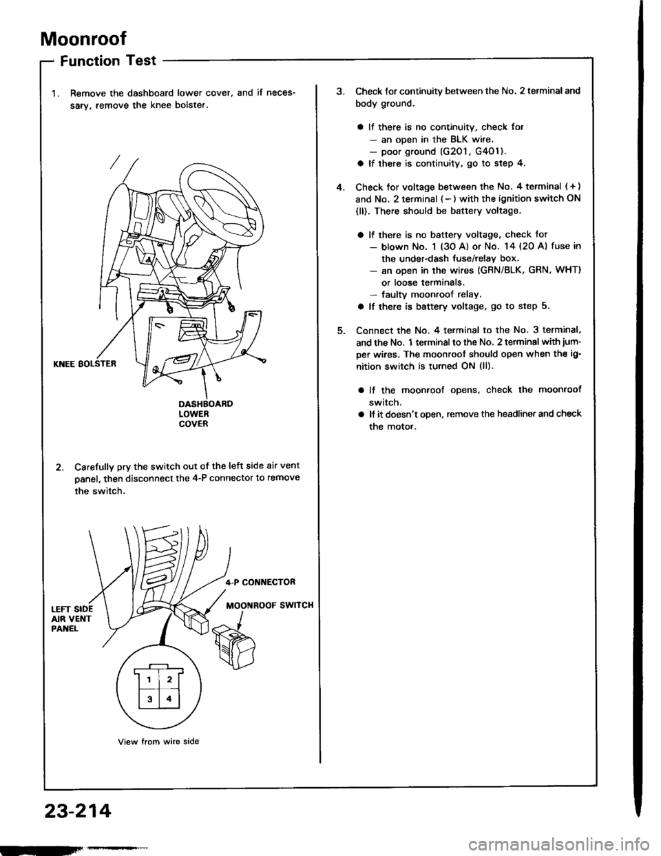
Remove the dashboard lower cover,
sarv, remove the knee bolste..
and if neces-
KNEE BOLSTER
DASHBOARDLOWERCOVER
2. Carefully pry the switch out of the left side air vent
panel, then disconnect the 4-P connector to remove
the switch.
4-P CONI{ECTOR
MOOi{ROOF SWITCH
View from wire side
.r--r
ll l2lf--T� --t
l314l
23-214
Check Jor continuity between the No. 2 terminal and
body ground.
a ll there is no continuity, check for- an ooen in the BLK wire.- poor ground (G201 , G4Ol ).
a lf there is continuity, go to step 4.
Check tor voltage between the No. 4 terminal ( + )
and No. 2 terminsl { - ) with the ignition switch ON
{ll). There should be battery voltage.
a lf there is no baftery voltage, check tot- blown No. 1 (3o Al or No. 14 {20 A) fuse in
the under-dash tuse/relay box.- an open in the wires (GRN/BLK, GRN, WHT)
or loose terminals.- faulty moonroof relay.
a lf there is battery voltage, go to step 5.
Connect the No. 4 terminal to the No. 3 terminal,
and the No. 1 terminal to the No, 2 terminal with jum-
per wires. The moonroot should open when the ig-
nition switch is turned ON (ll).
lf the moonroof ooens, check the moonroof
switch,
ll it doesn't open, remove the headlinet and check
the motor.
4.