1994 CADILLAC ELDORADO fuel pressure
[x] Cancel search: fuel pressurePage 154 of 398
Downloaded from www.Manualslib.com manuals search engine DISPLAY ON/OFF Button
Pressing this button will turn off the Driver Information Center,
Electronic Climate Control and Fuel Data Center displays. If
you have
the digital cluster the
fuel gage, Trip and odometer will also turn off.
While displays are off, pressing the INFORMATION button will turn on
only the Driver Information Center. If any other button is pressed or a
driving warning message needs to be displayed, or fuel level falls below
4 gallons, all the displays will come back on.
TRIP SET Button
Press and hold this button to set the Trip Odometer back to zero.
ENG/MET (English/Metric Button)
Press this button to switch from English (miles) and Degrees
(Fahrenheit), to Metric (kilometers) and Degrees (Celsius).
Driver Information Center Messages
These messages will appear if there is a problem sensed in one of your
vehicle’s systems. Vehicles that are first sold
in Canada or are export
vehicles will have a number after each message. This number he\
lps to
identify that message, which is only displayed
in English.
APPLY BRAKE TO SHIFT - 46
This message will appear if your vehicle is in “P” (Park) for about 15
seconds and the brake is not depressed. If you do not want this message
to appear,
you can cancel this message by holding the “OFF” and the
Blue (cooler) button on the Electronic Climate Control panel for about
5 seconds. Hold the same two buttons again to have this message
displayed again.
A/C OVERHEATED - A/C COMPRESSOR OFF - 15
If the refrigerant system ever reaches an over-pressure condition, this \
message will appear to tell you that the air conditioning compressor has
been turned off. Air conditioned air will not be delivered to cool your
vehicle. If the pressure returns to a normal operating range,
you must
select
“AUTO”, “DEFOG”, or Defrost to start the compressor. If this
message continues to appear, have the system repaired as
soon as
possible to avoid compressor damage.
142
Page 258 of 398
Downloaded from www.Manualslib.com manuals search engine Even though these figures are adjusted, they still represent what the
average driver
will get. Your fuel economy may be significantly higher or
lower, depending
on how, when, and where your vehicle is driven. Here
are some things you can do to increase fuel economy;
Combine errands into one trip.
Turn the engine off rather than letting it idle for more than a minute.
Have your Cadillac serviced as described in the maintenance booklet.
Keep tires inflated to recommended pressures.
Anticipate traffic stops.
Here are some things that
will lower fuel economy:
Quick acceleration.
Traveling at higher speeds. Traveling at 65 mph instead of 55 mph
0 Carrying unnecessary weight in the vehicle.
Rewing the engine. This is not necessary for your vehicle.
lowers fuel economy
by 15 percent.
Operating your vehicle with the suspension out of alignment or with
the wheels and tires out of balance.
Use of electrical accessories which require high amperage when they
are not needed.
Even things beyond your control such as weather conditions affe\
ct your
fuel economy. Driving up steep hills, in rain or snow, and into a strong
wind will lower fuel economy. In the lower
left corner of the fuel
economy window sticker from your vehicle is the range
of city and
highway
fuel economy you can expect to get from your Cadillac. If you
are doing everything to raise your fuel economy, but are still not within
this range, your vehicle may need service. Collect as much information
about your
fuel economy as you can find, (miles driven, gallon's of
fuel used, etc.) and provide it to your dealership for their review and
assistance. LA
Page 303 of 398
Downloaded from www.Manualslib.com manuals search engine i
NOTICE:
.. - , .., .. . **:. 7 ' . ..._ ^ . ,
Don't let anyone tell you that underinflation or overinflation is
all right. It's not. If your tires don't have enough air
(underinflation) you can get:
Too much flexing.,
Too much heat
Tire overloading
0 Badwear
Bad handling
0 Bad fuel economy.
If your tires have too much air (overinflation), you can ger:
Unusual wear
Bad handling
Rough ride
0 Needless damage from road hazards.
How to Check
Use a good quality pocket-type gage to check tire
pressure. Simply looking at the tires will not tell
you the pressure,
especially
if you have radial tires -- which may look properly' inflated even
if they're underinflated.
If your tires have valve caps, be sure to put them back on. They help
prevent leaks by keeping out dirt and moisture.
When to Check Check your tires once a month or more.
The Eldorado tire pressures are:
0 Front - 28 psi (190 Pa)
Rear - 26 psi (180 kPa)
Page 325 of 398

Downloaded from www.Manualslib.com manuals search engine Y
r
r I
i
r
!r:
i E
,r
i 'E
L HDLP LO R HDLP LO L HDLP HI R HDLP HI ION 3 COOL'FAN TRANS
I FUSE CENTER IDENTIFICATION I
ENGINE COMPARTMENT FUSE BLOCK
DlSTR 20A
SIR 20A - IGNITION CONTROL MODULE
- DIAGNOSTIC/ENERGY RESERVE
MODULE (DERM)
- DUAL POLE ARMING SENSOR PCM (ION 1OA
- PASS-Key@ DECODER MODULE INJ 10A
- POWERTRAIN CONTROL MODULE (PCM)
- 1,4,6, AND 7 FUEL INJECTORS
- 2.3.5. AND 8 FUEL INJECTORS INJ 1OA
ION
1 iOA - A/C REFRIGERANT PRESSURE SWITCH - TRANSAXLE RANGE SWITCH - STOP/BTSI/CRUISE BRAKE SWITCH - INSTRUMENT PANEL'CLUSTER - KEYLESS ENTRY MODULE - DIAGNOSTlCfENERGY RESERVE MODULE
- PERM2 ORN RING LIGHTS - TURN/HAZARD SWITCH ASSY. - CHIME MODULE - HEADLIGHT SWITCH - TWILIGHT SENTINEUDRL MODULE
- FUELPUMP - OIL PRESSURE SWITCH - POWERTRAIN CONTROL MODULE IPCMI
FUEL PUMP 20A
PCM (BAT) 1OA
RTD
, AT) 20A - RgAD SENSING SUSPENSION (RSS) MODUL A/C COMP 1OA
- POWERTRAIN CONTROL MODULE (PCM)
- A/C COMPRESSOR CLUTCH HDLPS 3OA
.~
- HEADLIGHT DIMMER SWITCH - HEADLIGHT RELAY "D (ENGINE COMF!
- DRL HEADLIGHT RELAY "E" (WITH DAYTIME
- POWERS C13 MICRO RELAY CENTER)
RUNNING LIGHTS)
E
STOP LP 2OA - STOP/BTSI/CRUISE SWITCH - STOPUGHT SWITCH CAPACITOR TURNIHAZ 20A - HAZARD FLASHER - TURN FLASHER RELAY - TURN FLASHER MODULE DRL 1 OA (CANADA) - DAV~ME RUNNI'NG LIGHTS (CANADA) ~ ~~
DRL 1 OA (CANADA)
HTD
W/S 1OA
L HDLP LO 1OA
- LEFT AND RIGHT LO BEAM HEADLAMP
- HEATED WINDSHIELD CONTROL MODULE
- LEFT LO BEAM HEADLAMP R HDLP LO 10A
L HDLP HI 1OA - RIGHT LO BEAM HEADLAMP
- LEFT HI BEAM HEADLAMP R HDLP HI 1OA
IGN
3 10A - RIGHT HI BEAM HEADLAMP
- REAR DEFOGGERRELAY - ELECTRONIC LEVEL CONTROL IELCI - HEATED WINDSHIELD - HEATER AND A/C PROGRAMMER - CRUISE CONTROL
..
COOLING FAN 1OA - MENDED TRAVEL BRAKE SWITCH - POWERTRAIN CONTROL MO'DULE (PCM) - COOLING FAN RELAYS 1,2, AND 3 - FRONT AND REAR HEATED OXYGEN SENSOR TRANSIECS 1 OA - OVERSPEED ALERT MODULE (=PORT) - POWER STEERING PRESSURE SWITCH - EXHAUST GAS REClRCULAilON (EGR) VALVE - TRANSAXLE SHIFT SOLENOIDS A & B - EVAPORATIVE EMISSION CONTROL
SOLENOID ~~
- POWERTRAIN CONTROL MODULE (PCM) - TORQUE CONVERTER CLUTCH SOLENOID - TCC BRAKESWlTCH
313
Page 326 of 398
Downloaded from www.Manualslib.com manuals search engine I 30AC.B. I
A
I I 60A
E
I 60A I
I I 50A
4
I 40A 1
n
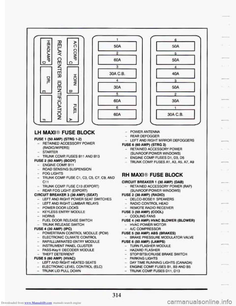
LH MAXI8 FUSE BLOCK
FUSE 1 (50 AMP) (STRG 1-2)
- RETAINED ACCESSORY POWER (RADIO/WIPERS)
- STARTER
- TRUNK COMF FUSES 81 1 AND 813
FUSE 2 (60 AMP) (BODY)
- ENGINE COMI? B11
- ROAD SENSING SUSPENSION
- FOG LIGHTS
- TRUNK COMF! FUSE C1, C3, C5, C7, C9, AND
c11
- TRUNK COMF! FUSE C13 (EXPORT)
- REAR FOG LIGHT (EXPORT)
CIRCUIT BREAKER 3 (30 AMP) (SEAT)
- LEFT AND RIGHT POWER SEAT SWITCHES
- LEFT AND RIGHT LUMBAR RELAYS
- POWER DOOR LOCKS
- KEYLESS ENTRY MODULE
- HORNS
- FUEL DOOR RELEASE SWITCH - TRUNK RELEASE SWITCH
FUSE 4 (30 AMP) (IPC)
- POWERTRAIN CONTROL MODULE (PCM)
- ELECTRONIC CLIMATE CONTROL
- RAP/ILLUMINATED ENTRY MODULE
- INSTRUMENT PANEL CLUSTER
- PASS-Key@ DECODER MODULE
- THEFT DETERRENT
FUSE 5 (SO AMP) (HVAC)
- LEFT AND RIGHT HEATED SEATS
- ELECTRONIC LEVEL CONTROL (ELC)
- TRUNK LID PULL DOWN
- POWER ANTENNA
- REAR DEFOGGER
- LEFT AND RIGHT MIRROR DEFOGGERS
FUSE 6 (60 AMP) (STRG 3)
- RETAINED ACCESSORY POWER
(SUNROOF/POWER WINDOWS)
- ENGINE COMF! FUSES Dl, D3, D5
- TRUNK COMF! FUSES Al, A3, A5, Ai', A9
RH MAXI8 FUSE BLOCK
CIRCUIT BREAKER 1 (30 AMP) (DAB)
- RETAINED ACCESSORY POWER (RAP)
(SUNROOF/POWER WINDOWS)
FUSE 2 (30 AMP) (RADIO)
- DELCO-BOSE@ SPEAKERS
- RADIO CONTROL HEAD
- REMOTE RADIO RECEIVER
FUSE 3 (50 AMP) (COOL)
FUSE
4 (40 AMP) HVAC BLOWER (BLOWER)
- COOLING FANS
- HVAC POWER MOTOR
- A/C COMPRESSOR
FUSE 5 (50 AMP) ABS (BRAKES)
FUSE
6 (50 AMP) (LAMPS)
- BRAKE PRESSURE MODULATOR VALVE
- TURN FLASHER MODULE
- HAZARD FLASHER
- STOP/BTSI/CRUISE BRAKE SWITCH
- PARKING LIGHTS
- DAY TIME RUNNING LIGHTS (CANADA)
- ENGINE COME FUSES B1,W AND B5
- TRUNK COMF! FUSES Dl 1, Dl3
314
Page 332 of 398
Downloaded from www.Manualslib.com manuals search engine The Northstar engine is designed to require less maintenance than many
other DOHC
V-8 engines. Engine systems are designed to remind the
driver when service is required.
An oil life index indicator monitors
ongoing operating conditions and reminds the driver when an oil change
is needed.
A low coolant warning message keeps track.of the level of this
vital fluid. Direct acting hydraulic tappets provide maintenance free zero
lash operation
of the 32 valves from idle to the 6500 rpm redline. The
camshafts are driven by
a two stage roller chain assembly which is
designed
to provide quiet maintenance free Operation. Platinum tipped
,spark plugs increase the replacement interval
to 100,000 miles.
The four valve per cylinder design provides more efficient engine
breathing which results in higher power than comparable
two valve
engines. The central location
of each spark plug ensures a fast and
complete burning of the fuel/air mixture. The induction system uses
smooth thermoplastic tubes to channel air into the cylinders. The
smoothness
of the tubes is equivalent to the elaborate port polishing
methods used for race car engines. Careful design using the shape and
length
of the tubes boosts horsepower by using sonic pressure waves
created by the motion
of the inlet valves to increase the amount of air
entering ,each cylinder.
The Northstar engine is also designed
to be very durable. The aluminum
block has cast-in-place iron cylinder liners for greater wear resistance.
High strength connecting rods support the free floating piston pins in
bronze bushings for superior high speed performance. The fillets
of the
nodular iron crankshaft undergo
a high pressure compression rolling
operation to improve their resistance to fatigue.
Quiet operation is enhanced by the use of special materials and designs.
The front cover of the engine is stamped from laminated steel which
damps out noise. Special cam cover gasket seals isolate valve train
operation.The fuel injectors are placed inside the induction system
housing
to eliminate- the clicking noise which is common to other fuel
injected engines.
The Northstar engine is designed to provide years of efficient. reliable.
satisfying operation.
7
320
Page 338 of 398
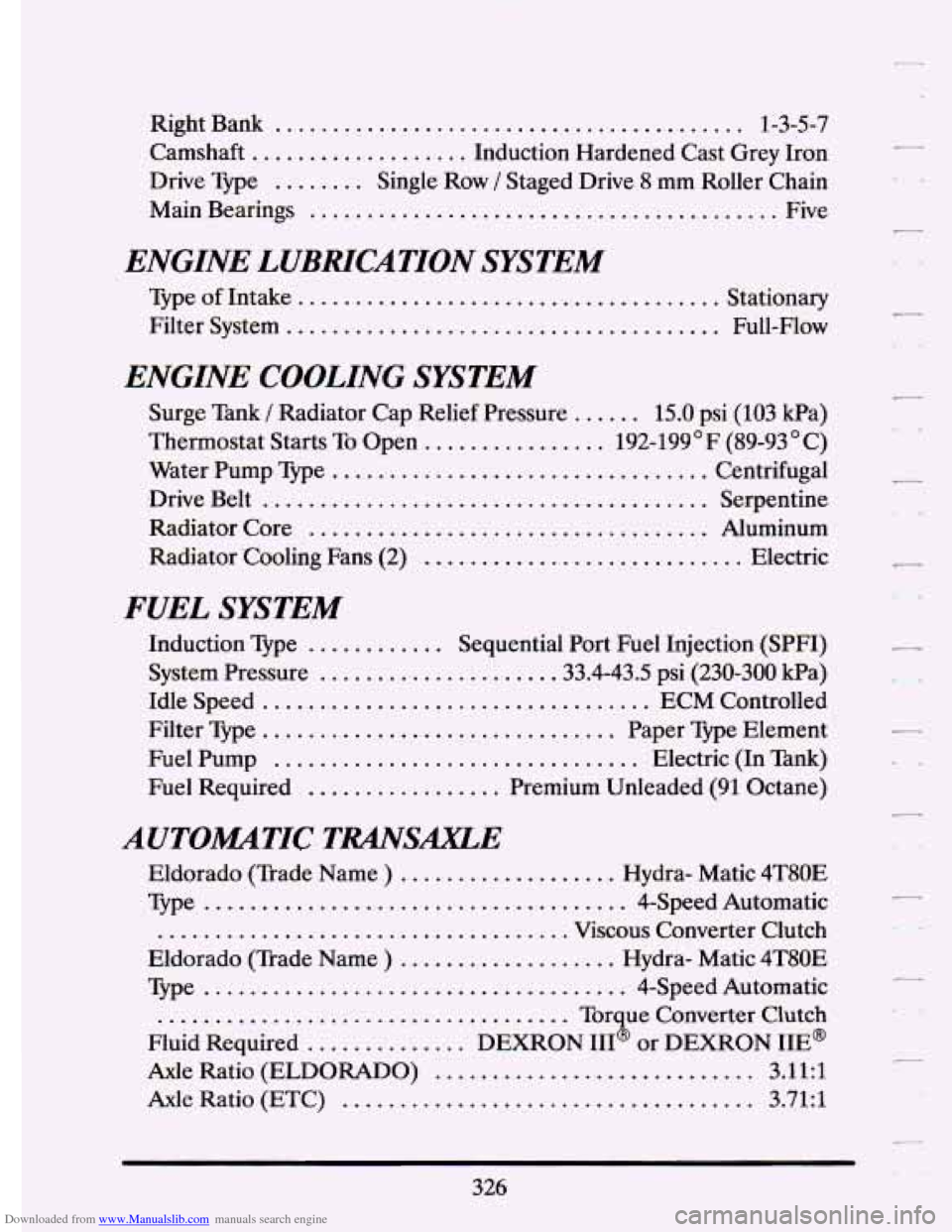
Downloaded from www.Manualslib.com manuals search engine Right Bank ......................................... 1-3-5-7
Camshaft
................... Induction Hardened Cast Grey Iron
Main Bearings
......................................... Five
Drive
Type
........ Single Row / Staged Drive 8 mm Roller Chain
ENGI. LUBRICATION SYSTEM
Type of Intake. .................................... Stationary
Filter System
...................................... Full-Flow
ENGINE COOLING SYSTEM
Surge Tank / Radiator Cap Relief Pressure ...... 15.0 psi (103 Pa)
Water Pump Type
.................................. Centrifugal
,Drive Belt
....................................... Serpentine
Radiator Core
................................... Aluminum
Radiator 'Cooling Fans (2)
............................ Elec.tric
Thermostat
Starts To Open
................ 192-199'F (89-93 C)
FUEL SYSTEM
Induction Type ............ Sequential Port Fuel Injection,(SPFI)
System Pressure
.................... .33.4-43.5 psi (230-300 kPa)
Idle Speed
.................................. ECM Controlled
Filter Type
............................... Paper Type Element
Fuel Pump
................................ Electric (In Tank)
Fuel Required
................. Premium Unleaded (91 Octane)
AUTOMTIC TRANSAXLE
Eldorado (Trade Name ) ................... Hydra- Mafic 4T80E
Type
..................................... 4-Speed Automatic
.................................... Viscous Converter Clutch
Eldorado (Trade Name
) ................... Hydra- Matic 4T80E
Type
..................................... 4-Speed Automatic
Fluid Required
.............. DEXRON III@ or DEXRON IIE@
Axle Ratio (ETC) .................................... 3.71:l
.................................... Torque Converter Clutch
Axle Ratio (ELDORADO) ............................ 3.11:l
326
r