Page 522 of 1254
TROUBLE
DIAGNOSES
Selfdiagnosis -
Mode I
MODE I _
BULB CHECK
In this mode,
rhe FED L.E.D. in
th6 E.c
U.
and rhe
CHECK
ENGINE LIGHT n lh€ insltum€nl panelsl,ay
"ON'.
ll elrher€main "oFF
, checkrhe
bllb in rhe cHEcK ENGINE
LIGHT or lhe RED
L E.D
MODE I _
MALFUNCTION WAFNING
. Th6
FED LE.D..nd OE CHECK ENGINE LIGHT
{llltun oli
when nomal @ndnlo is deleted.
Sell-diagnosis -
Mode ll (Selfuiagnostic
results)
DESCFIPnON
In this mode, a mallunclion code ls lndi€l€d bylh€ numbd ol
llashes iioh
the FED L.E.D. orlhe CHECK ENGINE LIGHT as
LonA (0.6
s€6nd) blinking ind
€les the number ot len dtgis
and shorr (o.3
s€6nd) blinkng indicates
the nudber ot singto
digils.
Fof exampl6, rh6 r€d L.E.D. f.sh€s once lor
0.6 se@nds and
then itllashes lwice lor 0.3 s€@nds. Th s ind
€tes the number
''l2 and €f6rc lo a malfuncton in
the a r llow meter. tn fi s
'' " ns ar€ c.
code nJnbers.
ol.Drav @de t bre
EF &EC-22
Page 1160 of 1254

HEADLAMP
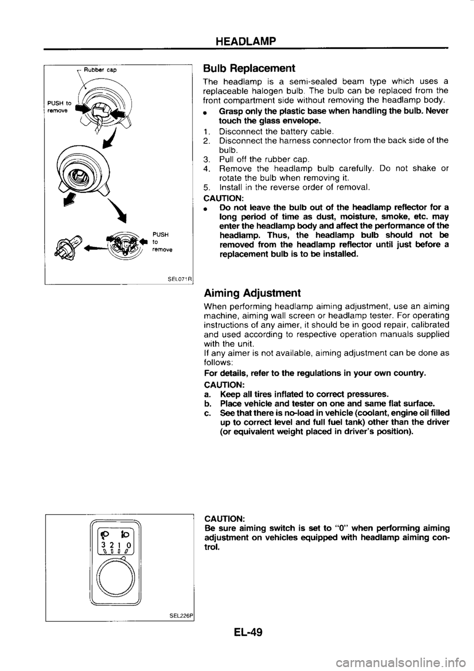
PUSH Io
\
_@. PUSH
lo Bulb
Replacement
The headlamp is
a semi-sealed beam type which
uses a
replaceable halogen
bulb. The
bulb can
be replaced from
the
f ront compartment side without
removing the headlamp
body.
r Grasp
only the plastic
base when
handling the bulb.
Never
touch the glass
envelope.
1. Disconnect the
battery cable.
2. Disconnect the
harness connector from
the back side ol the
bulb.
3. Pull
off the
rubber cap.
4. Remove the headlamp
bulb carefully. Do
not shake or
rotate the bulb when removing it.
5. Install
in the reverse
order of removal.
CAUTION:
o Do
not leave the bulb out of the headlamp
reflector for a
long period
of time as dust, moisture,
smoke, etc. may
enter the headlamp
body and aflect the pedormance
of the
headlamp. Thus, the headlamp
bulb should not
be
removed from
the headlamp reflector until just
before a
replac€ment bulb is
to be installed.
Aiming Adjustment
When performing
headlamp aiming adjustment, use
an aiming
machine, aiming wall screen or headlamp
lester. For
operating
instructions of any aimer, it should be in good
repair, calibrated
and used according to
respective operation manuals
supplied
with the unit.
lf any aimer is
not available, aiming adjustment can be done as
Iollows:
For details, reter
to the regulations in your
own country.
CAUTION:
a. Keep all tires inflated to correcl pressures.
b. Place vehicle
and tester on one
and same flat surface-
c. See that there
is noload in vehicle (coolant,
engine oil filled
up to correct level
and tull tuel tank) other than the driver
(or equivalent weight placed
in driver's position).
CAUTION: Be sure aiming switch
is set to "0"
when performing
aiming
adiustment on
vehicles equipped with
headlamp
aiming con-
trol.
lF-bl
l3 2
I 0l
L,\_-! S l l
,n
[) \/
EL-49
Page 1174 of 1254

EXTERIOR
LAMP
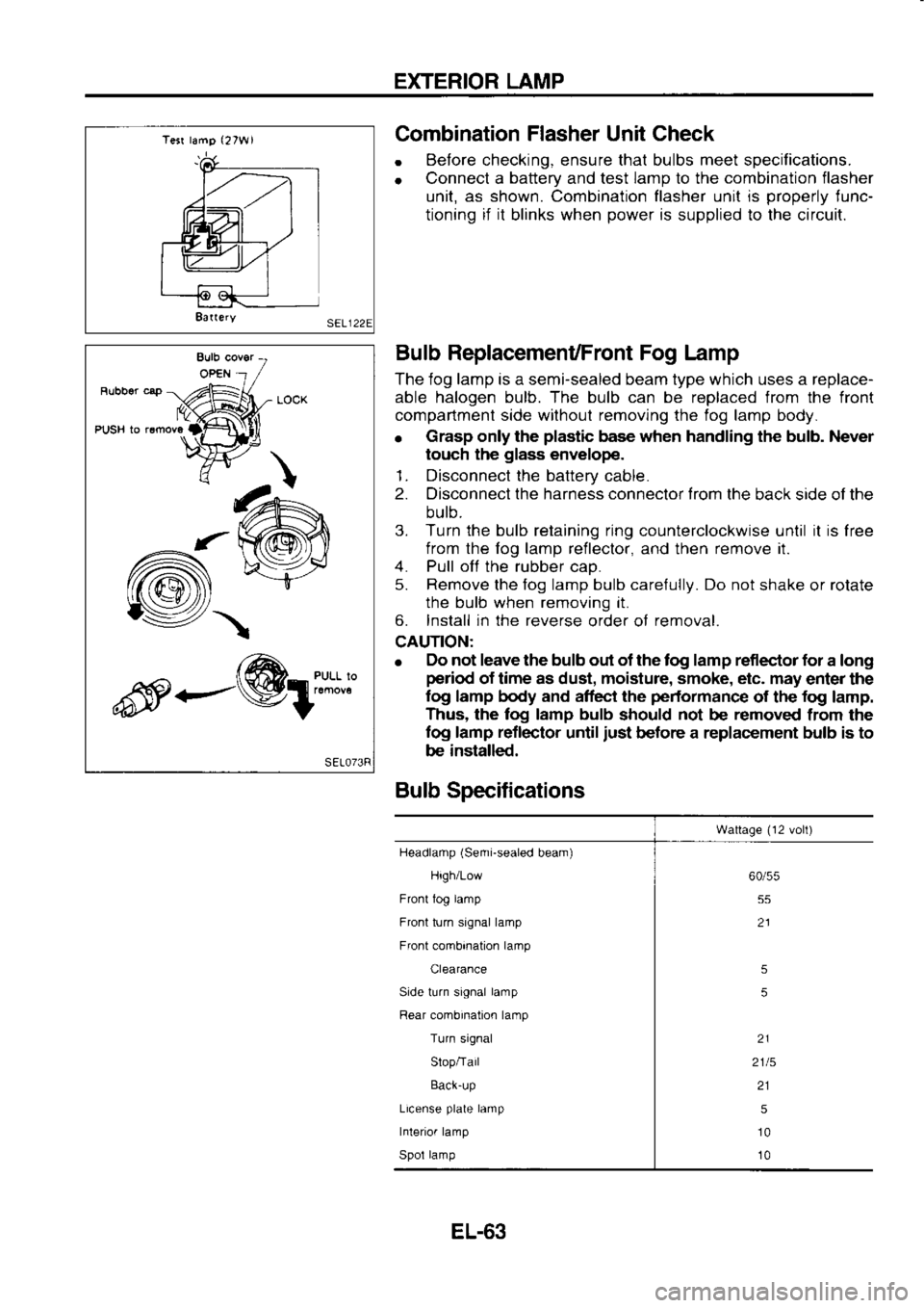
Tesr lamg (27W1
8a(ery Combination
Flasher
Unit Check
. Before
checking, ensure that bulbs meet specifications.
o Connect
a battery
and test lamp
to the combination
flasher
unit, as shown. Combination flasher unit is properly
lunc-
tioning if it
blinks when power
is supplied to the circuit.
Bulb ReplacemenUFront Fog Lamp
The iog lamp is a semi-sealed beam type which uses a replace-
able halogen bulb. The bulb can be replaced from the front
compartment side withoul removing the fog lamp body.
o Grasp
only the plastic
base when handling the bulb. Never
touch the glass
envelope.
1. Disconnect the battery
cable.
2. Disconnect the harness connector trom
the back side of the
bulb.
3. Turn the bulb retaining ring
counterclockwise until it
is
free
from the fog lamp reileclor,
and then remove
it.
4. Pull off
the rubber
cao.
5. Remove
the fog lamp bulb care{ully. Do not
shake or rolate
the bulb when removing it.
6. Install in the reverse
order of removal.
CAUTION:
e Elo
not leave the bulb out of the tog lamp reflector for
a long
period of time as dust, moisture, smoke, etc. may
enter the
log lamp body and affect the performance
of the fog
lamp.
Thus, the log lamp bulb
should not
be removed
from the
fog lamp reflector
until just
before a replacement bulb is to
be installed.
Bulb Specifications
Wattage (12
volt)
Headlamp (Semi-sealed
beam)
High/Low
Front tog lamp
Front turn signal lamp
Front combination lamp
Clearance
Side turn signal lamp
Rear combination lamp
Turn signal
Slop/Tail
Back-up
License plate
lamp
Interior lamp
Spol lamp 60/55
55
21
5
5
21
2115 215
10
10
-/\
<---@1:"*:l'l
EL-63
Page 1181 of 1254
METER
AND
GAUGES
E wrTH
TACHOhEIER
m
WITHOUT
MEL641
'sgq-=;
Inspection/Fuel
Gauge and Water Temperature
Gauge
CHECK POWEFI
SOURCE.
1) Turn
ignitron switch "ON".
2) Check vollage
between terminal
@
ano grouno.
Battery voltage
should exist. Check
the lollowing
items.
1) Harness
conlinu;ty
between battery termi-
nal and combination
meler
2) lgnilion relay
3) Fusible
link and fuse
4) lgnrlion
switch
CHECK GAUGE OPERATION,
1) Turn
ignition switch "ON".
2) Connect
terminal
@ and
ground
wrth wire
through 3.4W test
bulb.
3) Check operation of gauge.
Gauge should move
smoothly to tull
scate.
WTTH
IACHOMEIER
@: Fue
gauge
O Water
temp gauge
MEL642A
EL-70
Page 1206 of 1254
LOCATION
OF ELECTRICAL
UNIT
Front Compartment
Alr conditionor r6lay (Blue)
L.H.D.
MODEL
Reley box-3
Futlblc llnk
lnd tu.o
box R€lay
box-1
Relay box-2
Rolay box-1 rnd rclay
box-2
Hom r6lay (Grey)
E.C.C.S r€ley
lGreen)(SR2oOE, cA160E)
Radrelor fan rel.y
lBlue) (LO2O-
)
Radlaior lan r€tay (Btuel
(GA16DE)
fen r€lay
{Brown) (SR2oDE,
L020 )
Rediator fan r€ley (Blue)
(GA16DE)
Engine room fan r6tay (Btue) (GA16OE)
Radialor tan r€tay (Btue)
(SFI2ODE)
Fronl fog lamp r6tay (Blus)
(GA16DE, LD20-tt)
Rediator ten r6lay
{Btue)
Rolay
box-3 (SR2oDE)
.nd wlpor !mp.
7
LD201t)
(SR2oDE) \ |
Heeter rsley (Blue)]
] I I
(GA16DE. Lom-[)
J /
Radiator len r6lay (8lue)
(SR20DE)
Air conditioner relay (Bluo)
(GA16DE)
Air condilioner r€lay (8rown)
(LO20-tt)
Blow€r r€lay (Black)lSR2oDE)
Bulb ch6ck rslay (Atue)
(Lo2ojtl
EL-95 MEL65IB