1993 CHEVROLET PLYMOUTH ACCLAIM air condition
[x] Cancel search: air conditionPage 446 of 2438

for unleaded fuel. During combustion, fuel with
MMT coats the entire tip of the spark plug with a
rust color deposit. The rust color deposits could be
misdiagnosed as being caused by coolant in the com-
bustion chamber. MMT deposits do not affect spark
plug performance.
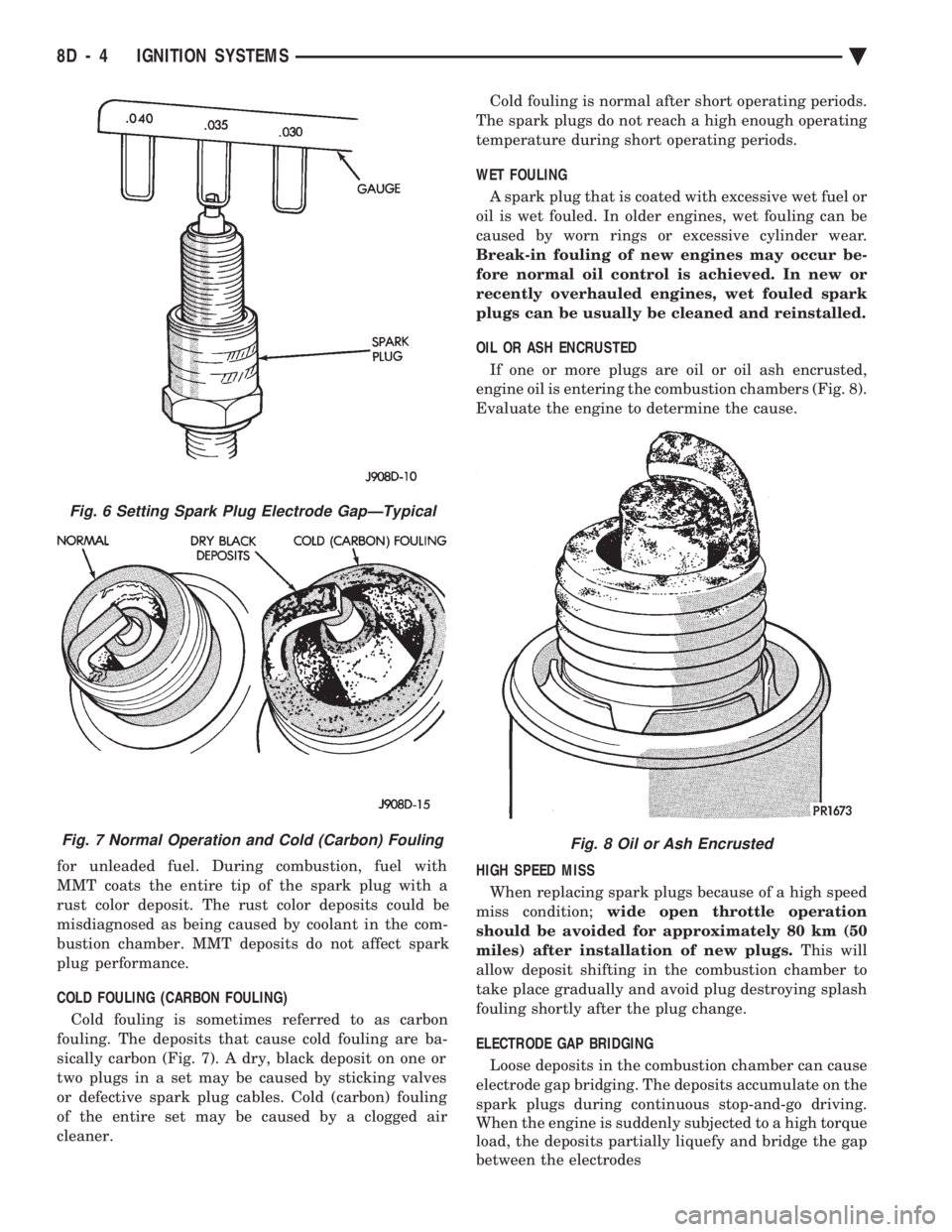
COLD FOULING (CARBON FOULING)
Cold fouling is sometimes referred to as carbon
fouling. The deposits that cause cold fouling are ba-
sically carbon (Fig. 7). A dry, black deposit on one or
two plugs in a set may be caused by sticking valves
or defective spark plug cables. Cold (carbon) fouling
of the entire set may be caused by a clogged air
cleaner. Cold fouling is normal after short operating periods.
The spark plugs do not reach a high enough operating
temperature during short operating periods.
WET FOULING
A spark plug that is coated with excessive wet fuel or
oil is wet fouled. In older engines, wet fouling can be
caused by worn rings or excessive cylinder wear.
Break-in fouling of new engines may occur be-
fore normal oil control is achieved. In new or
recently overhauled engines, wet fouled spark
plugs can be usually be cleaned and reinstalled.
OIL OR ASH ENCRUSTED
If one or more plugs are oil or oil ash encrusted,
engine oil is entering the combustion chambers (Fig. 8).
Evaluate the engine to determine the cause.
HIGH SPEED MISS When replacing spark plugs because of a high speed
miss condition; wide open throttle operation
should be avoided for approximately 80 km (50
miles) after installation of new plugs. This will
allow deposit shifting in the combustion chamber to
take place gradually and avoid plug destroying splash
fouling shortly after the plug change.
ELECTRODE GAP BRIDGING
Loose deposits in the combustion chamber can cause
electrode gap bridging. The deposits accumulate on the
spark plugs during continuous stop-and-go driving.
When the engine is suddenly subjected to a high torque
load, the deposits partially liquefy and bridge the gap
between the electrodes
Fig. 6 Setting Spark Plug Electrode GapÐTypical
Fig. 7 Normal Operation and Cold (Carbon) FoulingFig. 8 Oil or Ash Encrusted
8D - 4 IGNITION SYSTEMS Ä
Page 448 of 2438

ing, detonation and cooling system malfunctions also
can cause spark plug overheating.
SPARK PLUG SERVICE
When replacing the spark plug and coil cables,
route the cables correctly and secure them in the ap-
propriate retainers. Failure to route the cables prop-
erly can cause the radio to reproduce ignition noise,
cross ignition of the spark plugs or short circuit the
cables to ground.
SPARK PLUG REMOVAL
Always remove the spark plug cable by grasping at
the spark plug boot turning, the boot 1/2 turn and
pulling straight back in a steady motion. (1) Prior to removing the spark plug spray com-
pressed air around the spark plug hole and the area
around the spark plug. (2) Remove the spark plug using a quality socket
with a rubber or foam insert. (3) Inspect the spark plug condition. Refer to
Spark Plug Condition in this section.
SPARK PLUG GAP ADJUSTMENT Check the spark plug gap with a gap gauge. If the
gap is not correct, adjust it by bending the ground
electrode (Fig. 6).
SPARK PLUG INSTALLATION (1) To avoid cross threading, start the spark plug
into the cylinder head by hand. (2) Tighten spark plugs to 28 N Im (20 ft. lbs.)
torque. (3) Install spark plug cables over spark plugs.
POWERTRAIN CONTROL MODULE (PCM)
The ignition system is regulated by the powertrain
control module (PCM) (Fig. 14). The PCM supplies
battery voltage to the ignition coil through the Auto
Shutdown (ASD) Relay. The PCM also controls the
ground circuit for the ignition coil. By switching the ground path for the coil on and off, the PCM adjusts
ignition timing to meet changing engine operating
conditions.
During the crank-start period the PCM advances
ignition timing a set amount. During engine opera-
tion, the amount of spark advance provided by the
PCM is determined by these input factors:
² coolant temperature
² engine RPM
² available manifold vacuum
The PCM also regulates the fuel injection system.
Refer to the Fuel Injection sections of Group 14.
DISTRIBUTOR PICK-UPÐPCM INPUT
The engine speed input is supplied to the power-
train control module (PCM) by the distributor pick-
up. The distributor pick-up is a Hall Effect device
(Fig. 15 or Fig. 16).
A shutter (sometimes referred to as an interrupter)
is attached to the distributor shaft. The shutter con-
tains four blades, one per engine cylinder. A switch
plate is mounted to the distributor housing above the
shutter. The switch plate contains the distributor
Fig. 14 Powertrain control module (PCM)
Fig. 15 DistributorÐ2.2L and 2.5L TBI Engines
Fig. 13 Spark Plug Overheating
8D - 6 IGNITION SYSTEMS Ä
Page 458 of 2438

(3) Inspect the spark plug condition. Refer to Spark
Plug Condition in this section.
SPARK PLUG GAP ADJUSTMENT
Check the spark plug gap with a gap gauge. If the
gap is not correct, adjust it by bending the ground
electrode (Fig. 6).
SPARK PLUG INSTALLATION
(1) Start the spark plug into the cylinder head by
hand to avoid cross threading. (2) Tighten spark plugs to 28 N Im (20 ft. lbs.)
torque. (3) Install spark plug cables over spark plugs.
IDLE RPM TESTÐ2.5L AND 3.0L ENGINES
WARNING: APPLY PARKING BRAKE AND/OR BLOCK
WHEELS BEFORE PERFORMING IDLE CHECK OR
ADJUSTMENT, OR ANY TESTS WITH A RUNNING
ENGINE.
Engine idle set rpmshould be recorded when the
vehicle is first brought into shop for testing. This
will assist in diagnosing complaints of engine stalling,
creeping and hard shifting on vehicles equipped with
automatic transaxles. Proceed to the Throttle Body Minimum Airflow pro-
cedures in Group 14.
IGNITION TIMING PROCEDUREÐ2.2L TBI, 2.5L
TBI, 2.5L MPI, AND 3.0L ENGINES
WARNING: APPLY PARKING BRAKE AND/OR BLOCK
WHEELS BEFORE PERFORMING SETTING IGNITION
TIMING OR PERFORMING ANY TEST ON AN OPER-
ATING ENGINE.
Proper ignition timing is required to obtain optimum
engine performance. The distributor must be correctly
indexed to provide correct initial ignition timing. (1) Set the gearshift selector in park or neutral and
apply the parking brake. All lights and accessories
must be off. (2) If using a magnetic timing light, insert the
pickup probe into the open receptacle next to the
timing scale window. If a magnetic timing unit is not
available, use a conventional timing light connected to
the number one cylinder spark plug cable. Do not puncture cables, boots or nipples with
test probes. Always use proper adapters. Punc-
turing the spark plug cables with a probe will
damage the cables. The probe can separate the
conductor and cause high resistance. In addition
breaking the rubber insulation may permit sec-
ondary current to arc to ground. (3) Turn selector switch to the appropriate cylinder
position. (4) Start engine and run until operating tempera-
ture is obtained. (5) With the engine at normal operating tempera-
ture, connect the DRBII scan tool to the data link
connector (diagnostic connector). Access the State Dis-
play screen. Refer to the appropriate Powertrain Diag-
nostics Procedures Manual. If not using the DRBII
scan tool, disconnect the coolant temperature
sensor electrical connector. The electric radiator
fan will operate and the malfunction indicator lamp
(instrument panel Check Engine light) will turn on
after disconnecting the coolant sensor or starting the
DRBII scan tool procedure. (6) Aim Timing Light at timing scale (Fig. 7 or Fig.
8) or read magnetic timing unit. If flash occurs when
timing mark is before specified degree mark, timing is
advanced. To adjust, turn distributor housing in direc-
tion of rotor rotation. If flash occurs when timing mark is after specified
degree mark, timing is retarded. To adjust, turn dis-
tributor housing against direction of rotor rotation.
Refer to Vehicle Emission Control Information label for
correct timing specification. If timing is within 62É of
value specified on the label, proceed to step (8). If
outside specified tolerance, proceed to next step. (7) Loosen distributor hold-down arm screw
enough to rotate the distributor housing (Fig. 9 or
Fig. 6 Setting Spark Plug GapÐTypical
8D - 16 IGNITION SYSTEMS Ä
Page 462 of 2438

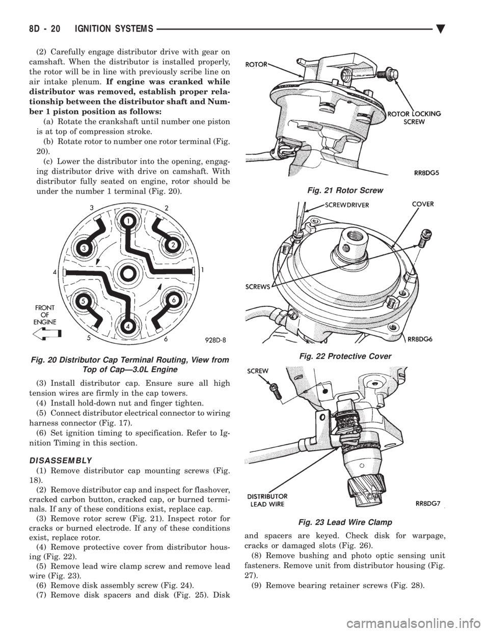
(2) Carefully engage distributor drive with gear on
camshaft. When the distributor is installed properly,
the rotor will be in line with previously scribe line on
air intake plenum. If engine was cranked while
distributor was removed, establish proper rela-
tionship between the distributor shaft and Num-
ber 1 piston position as follows: (a) Rotate the crankshaft until number one piston
is at top of compression stroke. (b) Rotate rotor to number one rotor terminal (Fig.
20). (c) Lower the distributor into the opening, engag-
ing distributor drive with drive on camshaft. With
distributor fully seated on engine, rotor should be
under the number 1 terminal (Fig. 20).
(3) Install distributor cap. Ensure sure all high
tension wires are firmly in the cap towers. (4) Install hold-down nut and finger tighten.
(5) Connect distributor electrical connector to wiring
harness connector (Fig. 17). (6) Set ignition timing to specification. Refer to Ig-
nition Timing in this section.
DISASSEMBLY
(1) Remove distributor cap mounting screws (Fig.
18). (2) Remove distributor cap and inspect for flashover,
cracked carbon button, cracked cap, or burned termi-
nals. If any of these conditions exist, replace cap. (3) Remove rotor screw (Fig. 21). Inspect rotor for
cracks or burned electrode. If any of these conditions
exist, replace rotor. (4) Remove protective cover from distributor hous-
ing (Fig. 22). (5) Remove lead wire clamp screw and remove lead
wire (Fig. 23). (6) Remove disk assembly screw (Fig. 24).
(7) Remove disk spacers and disk (Fig. 25). Disk and spacers are keyed. Check disk for warpage,
cracks or damaged slots (Fig. 26). (8) Remove bushing and photo optic sensing unit
fasteners. Remove unit from distributor housing (Fig.
27). (9) Remove bearing retainer screws (Fig. 28).
Fig. 21 Rotor Screw
Fig. 22 Protective Cover
Fig. 23 Lead Wire Clamp
Fig. 20 Distributor Cap Terminal Routing, View from Top of CapÐ3.0L Engine
8D - 20 IGNITION SYSTEMS Ä
Page 469 of 2438

mal wear can usually be cleaned, have the electrodes
filed and regapped, and then reinstalled. Some fuel refiners in several areas of the United
States have introduced a manganese additive (MMT)
for unleaded fuel. During combustion, fuel with MMT
may coat the entire tip of the spark plug with a rust
colored deposit. The rust color deposits can be misdi-
agnosed as being caused by coolant in the combustion
chamber. Spark plug performance is not affected by
MMT deposits.
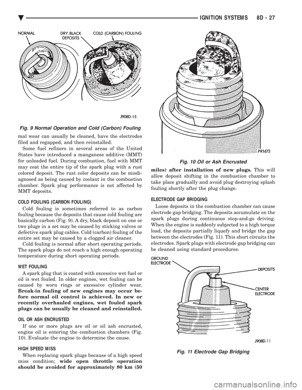
COLD FOULING (CARBON FOULING) Cold fouling is sometimes referred to as carbon
fouling because the deposits that cause cold fouling are
basically carbon (Fig. 9). A dry, black deposit on one or
two plugs in a set may be caused by sticking valves or
defective spark plug cables. Cold (carbon) fouling of the
entire set may be caused by a clogged air cleaner. Cold fouling is normal after short operating periods.
The spark plugs do not reach a high enough operating
temperature during short operating periods.
WET FOULING A spark plug that is coated with excessive wet fuel or
oil is wet fouled. In older engines, wet fouling can be
caused by worn rings or excessive cylinder wear.
Break-in fouling of new engines may occur be-
fore normal oil control is achieved. In new or
recently overhauled engines, wet fouled spark
plugs can be usually be cleaned and reinstalled.
OIL OR ASH ENCRUSTED If one or more plugs are oil or oil ash encrusted,
engine oil is entering the combustion chambers (Fig.
10). Evaluate the engine to determine the cause.
HIGH SPEED MISS When replacing spark plugs because of a high speed
miss condition; wide open throttle operation
should be avoided for approximately 80 km (50 miles) after installation of new plugs.
This will
allow deposit shifting in the combustion chamber to
take place gradually and avoid plug destroying splash
fouling shortly after the plug change.
ELECTRODE GAP BRIDGING
Loose deposits in the combustion chamber can cause
electrode gap bridging. The deposits accumulate on the
spark plugs during continuous stop-and-go driving.
When the engine is suddenly subjected to a high torque
load, the deposits partially liquefy and bridge the gap
between the electrodes (Fig. 11). This short circuits the
electrodes. Spark plugs with electrode gap bridging can
be cleaned using standard procedures.
Fig. 9 Normal Operation and Cold (Carbon) Fouling
Fig. 10 Oil or Ash Encrusted
Fig. 11 Electrode Gap Bridging
Ä IGNITION SYSTEMS 8D - 27
Page 483 of 2438

(2) With engine running, move test probe along
entire length of all cables (approximately 0 to 1/8
inch gap). If punctures or cracks are present there
will be a noticeable spark jump from the faulty area
to the probe. Cracked, leaking or faulty cables should
be replaced. Use the following procedure when removing the
high tension cable from the spark plug. First, remove
the cable from the retaining bracket. Then grasp the
terminal as close as possible to the spark plug. Ro-
tate the cover (boot) slightly and pull straight back.
Do not use pliers and do not pull the cable at an
angle. Doing so will damage the insulation, cable
terminal or the spark plug insulator. Wipe spark
plug insulator clean before reinstalling cable
and cover. Resistance cables are identified by the words Elec-
tronic Suppression .
Use an ohmmeter to check cables for opens, loose
terminals or high resistance. (a) Remove cable from spark plug.
(b) Remove cable from the coil tower.
(c) Connect the ohmmeter between spark plug
end terminal and the coil end terminal. Resistance
should be within tolerance shown in the cable re-
sistance chart. If resistance is not within tolerance,
replace cable assembly. Test all spark plug cables
in same manner.
SPARK PLUG SERVICE
When replacing the spark plug cables, route the ca-
bles correctly and secure them in the appropriate re-
tainers. Incorrectly routed cables can cause the radio
to reproduce ignition noise. It can also cause cross ig-
nition of the spark plugs or short circuit the cables to
ground.
SPARK PLUG REMOVAL
Always remove cables by grasping at boot, rotating
the boot 1/2 turn, and pulling straight back in a
steady motion. (1) Prior to removing the spark plug spray com-
pressed air around the spark plug hole and the area
around the spark plug. (2) Remove the spark plug using a quality socket
with a rubber or foam insert. (3) Inspect the spark plug condition. Refer to
Spark Plug Condition in this section.
SPARK PLUG GAP ADJUSTMENT
Check the spark plug gap with a gap gauge. If the
gap is not correct, adjust it by bending the ground
electrode (Fig. 6).
SPARK PLUG INSTALLATION
(1) To avoid cross threading, start the spark plug
into the cylinder head by hand. (2) Tighten spark plugs to 28 N Im (20 ft. lbs.)
torque. (3) Install spark plug cables over spark plugs.
IDLE RPM TEST
WARNING: BE SURE TO APPLY PARKING BRAKE
AND/OR BLOCK WHEELS BEFORE PERFORMING
ANY ENGINE RUNNING TESTS.
Engine idle set rpmshould be tested and recorded
as it is when the vehicle is first brought into shop
for testing. This will assist in diagnosing complaints
of engine stalling, creeping and hard shifting on ve-
hicles equipped with automatic transaxle. Refer to the
Throttle Body Minimum Airflow procedures in Group
14.
IGNITION TIMING PROCEDURE
Ignition timing cannot be changed or set on Turbo
III, 3.3L or 3.8L engines. For diagnostic information,
refer to the DRBII scan tool and the appropriate
Powertrain Diagnostics Procedures manual.
CABLE RESISTANCE CHART
Fig. 6 Setting Spark Plug GapÐTypical
Ä IGNITION SYSTEMS 8D - 41
Page 513 of 2438

(3) Remove four screws from ash receiver/cup
holder housing. (4) For installation reverse above procedures.
AIR CONDITIONING CONTROLREPLACEMENT
(1) Disconnect battery negative cable and isolate
or remove fuse #2 prior to removing switch or wires
may short to ground. (2) Remove center bezel. Disconnect ash receiver
lamp socket. (3) Remove glove box assembly. Refer to Glove Box
Assembly Replacement. (4) Reach through glove box opening and discon-
nect vacuum lines. (5) Remove two control mounting screws (Fig. 50).
(6) Slide control rearward, disconnect cable, and
electrical wiring. (7) Remove unit.
(8) For installation reverse above procedures.
CIGAR LIGHTER ASSEMBLY REPLACEMENT
(1) Remove center bezel. Disconnect ash receiver
lamp socket. (2) Remove two screws from bezel of the lighter as-
sembly. (3) Pull assembly rearward and disconnect wiring.
(4) For installation reverse above procedures.
TRAVELER/MESSAGE CENTER REPLACEMENT
(1) Remove cluster bezel.
(2) Remove four mounting screws.
(3) Pull unit rearward and disconnect wiring.
(4) For installation reverse above procedures.
INSTRUMENT PANEL
INSTRUMENT PANEL TOP COVER REPLACEMENT
(1) Lift up rearward edge of instrument panel top
cover. (2) Pull panel rearward to remove.
(3) To install: position top cover and snap into
place, pull rearward for proper fit.
INSTRUMENT PANEL REPLACEMENT
CAUTION: Disconnect negative battery cable, in en-
gine compartment, before servicing instrument
panel.
(1) Disconnect battery negative cable and isolate
or remove fuse #2 prior to removing switch or wires
may short to ground. (2) Remove left and right A-pillar trim.
(3) Remove left and right cowl side trim.
(4) Remove glove box assembly. Refer to Glove Box
Assembly Replacement. (5) Remove four relays above glove box assembly.
(6) Reach through glove box opening and discon-
nect A/C control vacuum lines, radio noise suppressor
wires, and blower motor/cycling switch wires. (7) Remove hood release handle.
(8) Remove lower steering column cover.
(9) Remove lower left instrument panel silencer
and reinforcement. (10) Remove instrument panel center bezel.
(11) Remove floor console. Refer to Group 23,
Body. (12) Remove radio, A/C control, cigar lighter, and
message center/traveler. (13) Disconnect demister hoses.
(14) Remove instrument panel top cover (Fig. 51).
(15) Disconnect battery to assure no air bag sys-
tem fault codes are stored. (16) Remove cluster refer to Cluster Assembly.
(17) Remove radio and rear window defogger be-
zels. (18) Lower steering column.
(19) Loosen instrument panel pivot bolts.
(20) Remove screws which attach instrument panel
to windshield fence line. (21) Allow panel to roll down slightly and discon-
nect remaining electrical connections. (22) With the aid of a helper remove panel pivot
bolts and remove panel from vehicle. (23) For installation reverse above procedures.
INTERIOR LAMP REPLACEMENT
The dome, overhead console and door lamps, if
equipped operate when the doors are open or head-
lamp switch is placed in courtesy position. The front
header reading lamp operates only when the lamp
push buttons are ON.
DOME LAMP
Pry either the forward or rearward edge of the lens
away from the bezel and replace lamp.
FRONT HEADER READING LAMP
Pull lamp from headliner. Disconnect wiring and
replace lamp.
Fig. 50 A/C Control
Ä INSTRUMENT PANEL AND GAUGES 8E - 21
Page 529 of 2438

CONDITION: US/METRIC MODES WILL NOT TOGGLE OR TRIP ODOMETER WILL NOTRESET
PROCEDURE
(1) Perform cluster self-diagnostics to determine if
push buttons are operational. (2) Refer to the Body Chassis Diagnostic Manual
to diagnose CCD Bus. The US/Metric toggle and trip
odometer reset are activated over the CCD Bus.
ODOMETER ADJUSTMENT
The odometer memory is no longer retained in the
cluster. This information is stored in the body con-
troller. Therefore, there is no adjustment procedure.
If the cluster is replaced odometer value will not
change. If the body controller is replaced the mileage
may be transferred using the DRB II. Refer to the
Body Chassis Diagnostic Manual for the procedure.
SWITCH AND PANEL COMPONENT SERVICE
MESSAGE CENTER REPLACEMENT
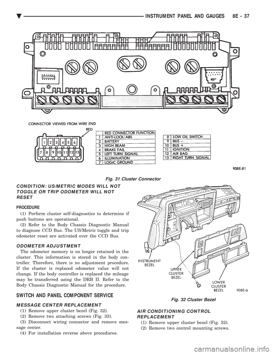
(1) Remove upper cluster bezel (Fig. 32).
(2) Remove two attaching screws (Fig. 33).
(3) Disconnect wiring connector and remove mes-
sage center. (4) For installation reverse above procedures.AIR CONDITIONING CONTROLREPLACEMENT
(1) Remove upper cluster bezel (Fig. 32).
(2) Remove two control mounting screws.
Fig. 31 Cluster Connector
Fig. 32 Cluster Bezel
Ä INSTRUMENT PANEL AND GAUGES 8E - 37