1993 CHEVROLET PLYMOUTH ACCLAIM water pump
[x] Cancel search: water pumpPage 368 of 2438

by tightening adjusting screw (Figs. 3 and 4 ).
Tighten pulley nut to 54 N Im (40 ft. lbs.) after ad-
justment.
GENERATOR/POWER STEERING PUMP BELT
The Poly-V generator/power steering pump belt is
provided with a dynamic tensioner (Fig. 5) to main-
tain proper belt tension. To remove or install this
belt, Release tension by rotating the tensioner clock-
wise
3.3/3.8L AND TURBO III ENGINE ACCESSORY
DRIVE BELT REMOVE AND INSTALL
GENERATOR, POWER STEERING PUMP, AIR
CONDITIONING COMPRESSOR AND WATER
PUMP DRIVE BELT The Poly-V Drive belt is provided with a dynamic
tensioner (Figs. 7 and 8) to maintain proper belt ten-
sion. To remove or install this belt. (1) Raise vehicle on hoist.
(2) Remove right front splash shield.
(3) Release tension by rotating the tensioner clock-
wise (Figs. 7 and 8). (4) Reverse above procedure to install.
Fig. 5 Release Belt Tensioner
Fig. 6 Belt Tension Chart
Fig. 4 Air Conditioning Belt Idler
7 - 26 COOLING SYSTEM Ä
Page 1063 of 2438
WIRING DIAGRAMS AC-AY BODY INDEX
Wiring Diagram
Name Sheet Number
ABS Data Link Connector ........................49
Airbag System ........................... .57, 58
Clockspring ...............................57
Diagnostic Module ..........................57
Interface Grommet ..........................58
Sensor-Left ...............................58
Sensor-Right ..............................58
Squib (Airbag Igniter) ........................57
Air Conditioning and Heater System (2.5L) .............53
A/C Switch ...............................53
Blower Motor ..............................53
Compressor ...............................53
Defrost Switch .............................53
Diode ...................................53
Illumination Lamps ..........................53
Low Pressure Switch .........................53
Resistor .................................53
Switch-Blower .............................53
Air Conditioning Variable Output Compressor ..........113
Air Exhaust Solenoid-Automatic Air Load Leveling ........40
Air Suspension System .................41, 42, 43, 44
Air Exhaust Solenoid .........................42
Air Suspension Relay .........................42
Air Suspension System Control Module .......41, 43, 176
Compressor Assembly ........................42
Compressor Motor ..........................42
Height Sensors ............................44
Shock Absorber ............................43
Solenoids ............................ .41, 44
Air Suspension System Control Module .........41, 43, 176
Antennas ............................. .118, 126
Anti-Lock Brake System ............45, 46, 47, 48, 49, 50
ABS System Relay ..........................47
Controller .................. .45, 46, 47, 48, 49, 50
Data Link Connector .........................49
Left Front Wheel Sensor .......................50
Left Rear Wheel Sensor .......................50
Modulator ............................ .45, 48
Pump Motor ..............................46
Pump and Motor Relay .......................46
Right Front Wheel Sensor ......................50
Right Rear Wheel Sensor ......................50
Yellow Lamp Relay ..........................49
Anti-Lock Brake System Controller .....45, 46, 47, 48, 49, 50
Anti-Lock Brake System Modulator Connectors .........172
Anti-Lock Brake System Controller Connector ..........175
Anti-Lock Brake System Modulator ...............45, 48
ATC In-line Connector ........................ .117
Automatic Air Load Leveling System ..............39, 40
Air Exhaust Solenoid .........................40
Compressor Assembly ........................40
Compressor Motor ..........................40Wiring Diagram
Name Sheet Number
Load Leveling Relay .........................40
Shock Absorber ............................40
Automatic Day/Night Mirror .................... .124
Automatic Temperature Control .............115, 116, 117
A/C Blower Motor ......................... .115
Ambient Sensor .......................... .117
ATC Control Switch ........................ .116
ATC In Line Connector ...................... .117
ATC Power Module ........................ .115
In Car Senso r............................ .115
In Car Sensor Motor ....................... .115
Sun Sensor ............................. .115
Water Sensor ............................ .117
Automatic Temperature Control (Radiator and
Compressor 3.3L & 3.8L) .................. .113, 114
A/C Ambient Temperature Switch ................114
A/C Compressor Clutch Relay ...................113
A/C Fan Cutout Switch ...................... .114
A/C High Pressure Cutout Switch ................114
A/C Low Pressure Switch .................... .114
A/C Variable Output Compressor .................113
Diode ................................. .113
Radiator Fan Motor ........................ .113
Radiator Fan Relay ........................ .114
Automatic Shutdown Relay .......................29
Automatic Temperature Control In-line Connector ........206
Automatic Temperature Control Module Connector .......200
Back-Up Lamp Relay ..........................33
Battery ...............................2,5,7,9
Body Computer 2 (Electronic Cluster) .........101, 102, 194
25-Pin Connector ...................... .101, 102
Body Computer 1 (Electronic Cluster) .........103, 104, 195
25-Pin Connector ...................... .103, 104
Data Link Connector ....................... .103
Halo Lamp .............................. .104
Relay ................................. .103
Body Computer (Mechanical Cluster w/Visual Message Ctr) ......................... .196, 197
Body Computer (Mechanical Cluster w/o Visual Message Ctr) ......................... .198, 199
Body Computer 1 (Mechanical Cluster w/o Visual Message Ctr) ..................... .108, 109, 110
25-Pin Connector ................... .108, 109, 110
Data Link Connector ....................... .110
Halo Lamp .............................. .108
Key-In Switch ............................ .109
Relay Bank ............................. .108
Body Computer 2 (Mechanical Cluster with Visual Message Ctr) ..................... .105, 106, 107
25-Pin Connector ................... .105, 106, 107
Data Link Connector ....................... .106
Halo Lamp .............................. .106
Key-In Switch ............................ .107
Ä WIRING DIAGRAMS AC-AY BODY 8W - 313
Page 1069 of 2438
Wiring Diagram
Name Sheet Number
Left Side Marker Lamp ...................... .163
Right Back-Up Lamp ....................... .164
Right Center High Mounted Stop Lamps ............164
Right Inboard Tail, Stop & Turn Signal Lamp .........164
Right License Lamp ........................ .164
Right Outboard Tail, Stop & Turn Signal Lamp ........164
Right Side Marker Lamp ..................... .164
Recliner Position Sense Resistor ..................154
Relay Bank ............................... .171
Relay Module ............................. .171
Relays ABS System Relay ..........................47
A/C Compressor Clutch .................54, 56, 113
Air Suspension .............................42
Automatic Shut Down .................. .15, 23, 29
Automatic Load Leveling .......................40
Back-Up Lamp .............................33
Door Lock/Unlock ......................... .140
Engine Starter .......................... .12, 13
Fan Control ............................. .114
Fuel Pump ...............................36
Horn ...................................63
Headlamp ................................68
Headlamp Door ............................68
Park Lamp .............................. .125
Power Antenna/Name Brand Speaker Relay ..........118
Pump and Motor Relay .......................46
Radiator Fan Control Relay A/C ................54, 56
Radiator Fan Relay ATC ..................... .114
Radiator Fan Relay-Heater ......................52
Safety Shut Down ...........................35
Yellow Lamp Relay ..........................49
Remote Keyless Entry ..................... .141, 142
Program Module .......................... .141
Remote Keyless Entry Module ...............141, 142
Right Body to Instrument Panel Wiring ...........192, 193
Right Front Wheel Sensor .......................50
Right Rear Wheel Sensor ........................50
RS Amplifier ........................... .122, 123
Safety Shut Down Relay ........................35
Seat Belt Warning System .......................67
Seat Belt Switch .............................67
Seat Track Position Sense Resistor .................154
Security Alarm Module Connector (Elec Cluster) ........202
Security Alarm Module Connector (Mech Cluster) ........203
Security Alarm System (Electronic Cluster) ........135, 136,
137, 138
Deck Lid Key Cylinder ...................... .135
Data Link Connector ....................... .136
Left Door Key Cylinder ...................... .135
Relay Bank ............................. .138
Relay Module ............................ .137
Right Door Key Cylinder ..................... .135
Security Alarm Hood Switch ...................136
Security Alarm Module .............135, 136, 137, 138
Security Lamp ........................... .136Wiring Diagram
Name Sheet Number
Security Alarm System (Mech Cluster w/VMC) ......127, 128,
129, 130
Deck Lid Key Cylinder ...................... .127
Data Link Connector ....................... .130
Left Door Key Cylinder ...................... .127
Relay Bank ............................. .130
Relay Module ............................ .129
Right Door Key Cylinder ..................... .127
Security Alarm Hood Switch ...................128
Security Alarm Module .............127, 128, 129, 130
Security Lamp ........................... .128
Security Alarm System (Mech Cluster w/o VMC) . . . .131, 132,
133, 134
Deck Lid Key Cylinder ...................... .131
Data Link Connector ....................... .134
Left Door Key Cylinder ...................... .131
Relay Bank ............................. .134
Relay Module ............................ .133
Right Door Key Cylinder ..................... .131
Security Alarm Hood Switch ...................132
Security Alarm Module .............131, 132, 133, 134
Security Lamp ........................... .132
Sensors Airbag Sensor .............................58
Ambient Sensor .......................... .117
Brake Fluid Level Sensor ......................98
Camshaft Position Sensor ......................28
Coolant Level Sensor .........................98
Crankshaft Position Sensor .....................28
Engine Coolant Temperature Sensors ..........17, 19, 25
Engine Oil Level Sensor .................... .31, 32
Heated Oxygen Sensors ................. .14, 19, 25
Height Sensors ............................44
In Car Senso r............................ .115
Left Front Wheel Sensor .......................50
Left Rear Wheel Sensor .......................50
MAP Sensors ........................ .18, 21, 26
Right Front Wheel Sensor ......................50
Right Rear Wheel Sensor ......................50
Sun Sensor ............................. .115
Throttle Position (Sensors) ................18, 21, 26
Transmission Output Speed Sensor ................34
Turbine Speed Sensor ........................34
Vehicle Speed Sensor .................. .17, 19, 25
Water Sensor ............................ .117
Windshield Washer Low Fluid Level Sensor ...........61
Solenoids Air Exhaust-Automatic Load Leveling Solenoid .........42
Air Suspension Solenoid ................... .41, 44
Deck Lid Release Solenoid ................... .159
EVAP/Purge Solenoids .................. .15, 20, 27
Exhaust Gas Recirculation Solenoids ..........14, 21, 26
Transmission Solenoid .................... .12, 35
Transmission TCC LU Solenoid ..................12
Splices Splice A1 ...........................4,6,8,10
Splice A3 .........................2,37,59,66
Splice A3-1 .....................2,6,8,10,69,71
Ä WIRING DIAGRAMS AC-AY BODY 8W - 319
Page 1575 of 2438
Flexible fuel vehicles can operate on a mixture of
up to 85 percent methanol, 15 percent unleaded gas-
oline. These vehicles also operate on mixtures con-
taining a lower percentage of methanol or just pure
unleaded gasoline. Engine components which are required for safe op-
eration using fuel containing methanol alcohol are
identified by a standard green color and/or display
the statement methanol compatible imprinted on the
component. To ensure continued safe operation, these
components must be serviced only with genuine MO-
PAR replacement parts. Methanol compatible parts for the 2.5L FFV (Flex-
ible Fuel Vehicle) engine include, but are not limited
to; the valve stem oil seals, all piston rings, the oil
fill cap, the fuel injectors, fuel rail, fuel pressure reg-
ulator, hoses and the vacuum control harness hose. BLOCK: All four cylinder cast iron blocks have
cast-in recesses in the bottom of each cylinder bore to
provide connecting rod clearance; especially needed
for 2.5L engines. The bores are also siamese to min-
imize engine length. A coolant passage is drilled
cross-ways through the siamese section to enhance
between the bore cooling on some engine types. A
partial open deck is used for cooling and weight re-
duction with oil filter, water pump, and distributor
mounting bosses molded into the front (radiator side)
of the block. Nominal wall thickness is 4.5 mm. Five
main bearing bulkheads and a block skirt extending
3 mm below the crankshaft center line add to the
blocks high rigidity with light weight. CRANKSHAFT: A nodular cast iron crankshaft is
used in TBI engines. A forged steel crankshaft is
used in the Turbo III engine. All engines have 5 main bearings, with number 3 flanged to control
thrust. The 60 mm diameter main and 50 mm diam-
eter crank pin journals (all) have undercut radiuses
fillets that are deep rolled for added strength. To op-
timize bearing loading 4 counterweights are used.
Hydrodynamic seals (installed in diecast aluminum
retainers) provide end sealing, where the crankshaft
exits the block. Anaerobic gasket material is used for
retainer-to-block sealing. No vibration damper is
used. A sintered iron (TBI engine and steel billet
Turbo III engines) timing belt sprocket is mounted
on the crankshaft nose. This sprocket provides mo-
tive power; via timing belt to the camshaft and inter-
mediate shaft sprockets (also sintered iron (TBI
engine and steel billet Turbo III engines) providing
timed valve, distributor, and oil pump actuation. PISTONS: Some Chrysler pistons have cast-in
steel struts at the pin bosses for autothermic control.
All 2.2L and 2.5L piston tops have cuts to provide
valve clearance. Some pistons are dished to provide
various compression ratios. Standard 2.2L and 2.5L
engines are designed for 9.5:1 and 8.9:1 compression
ratios respectively. The 2.5L piston is dished and is a
lightweight design to enhance engine smoothness.
The 2.2L turbo III uses dished pistons providing a
8.3:1 compression ratio. All standard 2.2/2.5L and
2.5L FFV engines use pressed-in piston pins to at-
tach forged steel connecting rods, 2.2L turbo III en-
gine uses a full floating piston pin and connecting
rod assembly. PISTONS RINGS: The 2.2/2.5L engines share
common piston rings throughout, including molybde-
num filled top ring for reliable compression sealing
and a tapered faced intermediate ring for additional
cylinder pressure control. The 2.5L FFV engine fea-
ture all chrome rings for enhanced long term dura-
bility under multi-fueled conditions. CYLINDER HEAD: The cylinder head is cast alu-
minum with in-line valves. The 2.2/2.5L and 2.5L
FFV valves are arranged with alternating exhaust
and intake. The intake and exhaust ports are located
in the rearward, facing side of the head. The Turbo
III valves are arranged in two inline banks, with the
ports of the bank of two intake valves per cylinder
facing toward the radiator side of engine and ports of
the bank of two exhaust valve per cylinder facing to-
ward the dash panel. The intake ports feed fast-burn
design combustion chambers (2.2/2.5L and 2.5L FFV
only) with the spark plug located close to the center
line of the combustion chamber for optimum effi-
ciency. An integral oil gallery within the cylinder
head supplies oil to the hydraulic lash adjusters,
camshaft, and valve mechanisms. CAMSHAFT: The nodular iron camshaft has five
bearing journals (2.2/2.5L and 2.5L FFV). The Turbo
III employs dual camshafts that have nine bearing
journals. Flanges at the rear journal control cam-
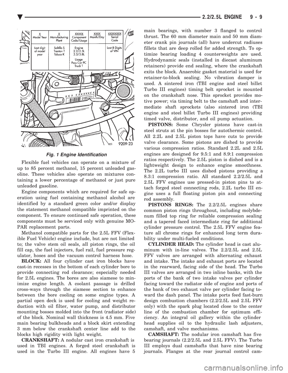
Fig. 1 Engine Identification
Ä 2.2/2.5L ENGINE 9 - 9
Page 1576 of 2438
shaft end play. A sintered iron (TBI engine and steel
billet Turbo III engines) timing belt sprocket is
mounted on the cam nose, and a hydrodynamic oil
seal is used for oil control at the front of the cam-
shaft. ACCESSORY SHAFT: The iron accessory shaft
has two bearing journals and is housed in the for-
ward facing side of the block. A hydrodynamic seal,
installed in an aluminum housing attached to the
block, provides retention, shaft thrust, and oil con-
trol. The accessory shaft is driven by the timing belt
through a sintered iron (TBI engine and steel billet
Turbo III engines) sprocket mounted on the nose of
the accessory shaft. The accessory shaft in turn
drives the oil pump and distributor on 2.2/2.5L and
2.5L FFV and the oil pump only on Turbo III. VALVES: The valves are actuated by roller cam
followers which pivot on stationary hydraulic lash
adjusters. The valve train with 40.6 mm (1.60 inch)
diameter intake valves and 35.4 mm (1.39 inch) di-
ameter exhaust valves employ viton rubber valve
stem seals except 2.5L FFv . the 2.5L FFV valve
stem seals are made of special rubber compound
which resist the deteriorating effects of methanol
fuel by-products that enter the oil during combus-
tion. Valve springs, spring retainers, and locks are
conventional. For Turbo III engines the valves are
actuated by roller tipped rocker arms with hydraulic
lash adjusters which pivot on a shaft. The valve train
with 33.88 mm (1.33 in.) diameter intake valves are
arranged in line opposite of the 29.26 mm (1.15 in.)
diameter exhaust valves employ locking valve stem
seals. Valve springs, spring retainers, and locks are
not interchangeable with other engines. BALANCE SHAFTS: 2.2 Turbo III and 2.5L en-
gines are equipped with two counter rotating balance
shafts installed in a carrier attached to the lower
crankcase. The shafts are interconnect through
gears. These gears are driven by a short chain from
the crankshaft, to rotate at two times crankshaft
speed. This counterbalances certain engine recipro-
cating forces. INTAKE MANIFOLDS:
All intake manifolds are
aluminum castings, attached to the cylinder head
with eight bolts. N.A. engines use a four branch de-
sign. This long branch fan design enhances low and
midspeed torque. It also features an integrally cast
water crossover passage to warm incoming fuel/air
mixture, plus an EGR mounting boss and PCV inlet. The Turbo III engine intake manifold is a log type
with tuned runners. The manifold is machined to ac-
cept fuel injectors near the ports of each cylinder. EXHAUST MANIFOLDS: The exhaust manifolds
are made of nodular cast iron for strength and high
temperatures. All naturally aspirated (N.A.) and tur-
bocharged engines exit exhaust gasses through a ma-
chined, articulated joint connection to the exhaust
pipe. 2.2/2.5L and 2.5L FFV manifolds intermesh
with the intake manifold at the cylinder head. N.A. engines use a four branch design with cylin-
ders one and four joined and cylinder two and three
joined to exit at the outlet. The Turbo III engine exhaust manifold also carries
the turbocharger. This manifold has a modified log
type collector with exhaust gasses directed to and
through the turbocharger to exit the conical (articu-
lated joint) outlet machined into the turbocharger ex-
haust elbow. ENGINE LUBRICATION: Refer to Group 0 Lu-
brication and Maintenance for recommended oil to be
used in various engine application. System is full
flow filtration, pressure feed type. The oil pump is
mounted within the crankcase and driven by the ac-
cessory shaft. Pressurized oil is then routed through
the main oil gallery, running the length of the cylin-
der block, supplying main and rod bearings with fur-
ther routing (for 2.2L turbo III and 2.5L engines) to
the lower balance shaft assemblies. Pistons are lubri-
cated from directed holes in the connecting rod as-
semblies. Camshaft and valve mechanisms are
lubricated from a full-length cylinder head oil gallery
supplied from the crankcase main oil gallery.
9 - 10 2.2/2.5L ENGINE Ä
Page 1584 of 2438
TIMING SYSTEM AND SEALS SERVICEÐEXCEPT TURBO III
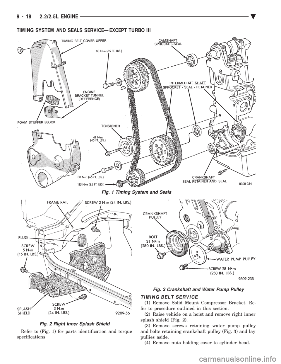
Refer to (Fig. 1) for parts identification and torque
specifications
TIMING BELT SERVICE
(1) Remove Solid Mount Compressor Bracket. Re-
fer to procedure outlined in this section. (2) Raise vehicle on a hoist and remove right inner
splash shield (Fig. 2). (3) Remove screws retaining water pump pulley
and bolts retaining crankshaft pulley (Fig. 3) and lay
pullies aside. (4) Remove nuts holding cover to cylinder head.
Fig. 2 Right Inner Splash Shield
Fig. 3 Crankshaft and Water Pump Pulley
Fig. 1 Timing System and Seals
9 - 18 2.2/2.5L ENGINE Ä
Page 1592 of 2438
valve spring retainer locks to become dislocated
when depressing the valve spring. Check and make
sure the locks are in their proper location. (3) Install valve cover as previously outlined in
this section.
VALVE SPRINGS AND VALVE STEM SEALS
REMOVAL
(1) Remove rocker arms as previously outlined in
this section. (2) Rotate crankshaft until piston is at TDC on
compression. (3) With air hose attached to adapter tool installed
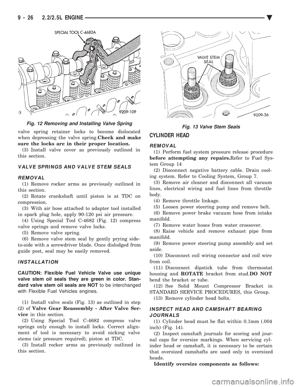
in spark plug hole, apply 90-120 psi air pressure. (4) Using Special Tool C-4682 (Fig. 12) compress
valve springs and remove valve locks. (5) Remove valve spring.
(6) Remove valve stem seal by gently prying side-
to-side with a screwdriver blade. Once dislodged from
guide post, seal may be easily removed.
INSTALLATION
CAUTION: Flexible Fuel Vehicle Valve use unique
valve stem oil seals they are green in color. Stan-
dard valve stem oil seals are NOT to be interchanged
with Flexible Fuel Vehicles engines.
(1) Install valve seals (Fig. 13) as outlined in step
(2) of Valve Gear Reassembly - After Valve Ser-
vice in this section.
(2) Using Special Tool C-4682 compress valve
springs only enough to install locks. Correct align-
ment of tool is necessary to avoid nicking valve
stems (air pressure required), piston at TDC. (3) Install rocker arms as previously outlined in
this section.
CYLINDER HEAD
REMOVAL
(1) Perform fuel system pressure release procedure
before attempting any repairs. Refer to Fuel Sys-
tem Group 14 (2) Disconnect negative battery cable. Drain cool-
ing system. Refer to Cooling System, Group 7. (3) Remove air cleaner and disconnect all vacuum
lines, electrical wiring and fuel lines from throttle
body. (4) Remove throttle linkage.
(5) Loosen power steering pump and remove belt.
(6) Remove power brake vacuum hose from intake
manifold. (7) Remove water hoses from water crossover.
(8) Raise vehicle and remove exhaust pipe from
manifold. (9) Remove power steering pump assembly and set
aside. (10) Disconnect coil wiring connector and coil wire
from coil. (11) Disconnect dipstick tube from thermostat
housing and ROTATEbracket from stud. DO NOT
bend the bracket or tube. (12) See Solid Mount Compressor Bracket in
STANDARD SERVICE PROCEDURES, this Group. (13) Remove cylinder head bolts.
INSPECT HEAD AND CAMSHAFT BEARINGJOURNALS
(1) Cylinder head must be flat within 0.1mm (.004
inch) (Fig. 14). (2) Inspect camshaft journals for scoring and jour-
nal caps for oversize markings. When servicing cyl-
inder head or camshaft, it is necessary to be certain
that oversized camshafts are used only in oversized
heads. Identify oversize components as follows:
Fig. 12 Removing and Installing Valve SpringFig. 13 Valve Stem Seals
9 - 26 2.2/2.5L ENGINE Ä
Page 1598 of 2438
Before installing the bolts, the threads should be
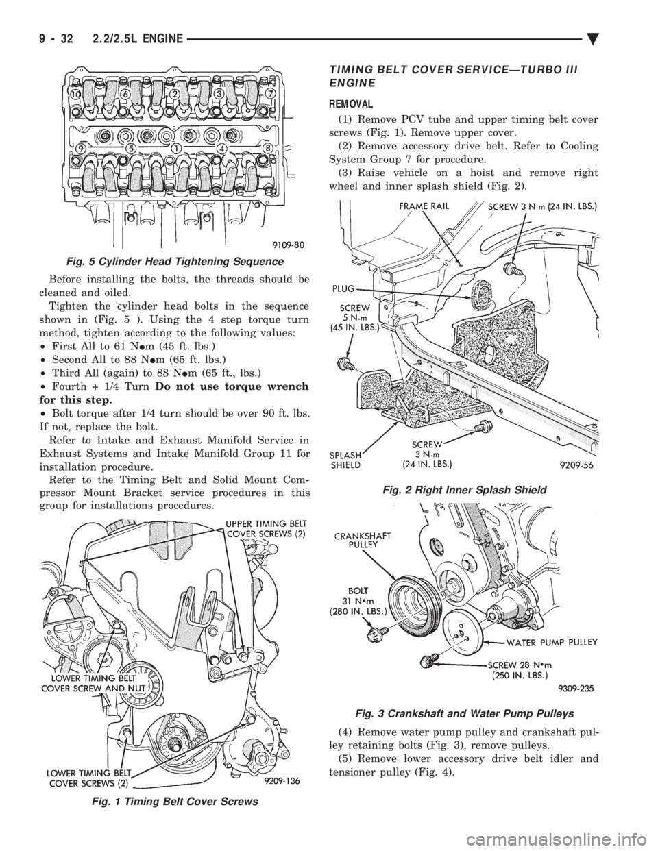
cleaned and oiled. Tighten the cylinder head bolts in the sequence
shown in (Fig. 5 ). Using the 4 step torque turn
method, tighten according to the following values:
² First All to 61 N Im (45 ft. lbs.)
² Second All to 88 N Im (65 ft. lbs.)
² Third All (again) to 88 N Im (65 ft., lbs.)
² Fourth + 1/4 Turn Do not use torque wrench
for this step.
² Bolt torque after 1/4 turn should be over 90 ft. lbs.
If not, replace the bolt. Refer to Intake and Exhaust Manifold Service in
Exhaust Systems and Intake Manifold Group 11 for
installation procedure. Refer to the Timing Belt and Solid Mount Com-
pressor Mount Bracket service procedures in this
group for installations procedures.
TIMING BELT COVER SERVICEÐTURBO III
ENGINE
REMOVAL
(1) Remove PCV tube and upper timing belt cover
screws (Fig. 1). Remove upper cover. (2) Remove accessory drive belt. Refer to Cooling
System Group 7 for procedure. (3) Raise vehicle on a hoist and remove right
wheel and inner splash shield (Fig. 2).
(4) Remove water pump pulley and crankshaft pul-
ley retaining bolts (Fig. 3), remove pulleys. (5) Remove lower accessory drive belt idler and
tensioner pulley (Fig. 4).
Fig. 1 Timing Belt Cover Screws
Fig. 5 Cylinder Head Tightening Sequence
Fig. 2 Right Inner Splash Shield
Fig. 3 Crankshaft and Water Pump Pulleys
9 - 32 2.2/2.5L ENGINE Ä