1993 CHEVROLET PLYMOUTH ACCLAIM low beam
[x] Cancel search: low beamPage 1287 of 2438

Wiring Diagram
Name Sheet Number
Reading Lamps ....................... .124, 126
Side Marker Lamp-Left .........45, 49, 50, 128, 132, 136
Side Marker Lamp-Right ........46, 49, 50, 131, 135, 139
Stop Lamp .......... .59, 128, 131, 132, 135, 136, 139
Tail Lamps .......128, 131, 132, 134, 135, 136, 138, 139
Trunk Lamp .......................... .122, 124
Transmission Range Lamp .....................51
Turn Lamp .................... .132, 135, 136, 139
Turn Signal Lamp-Left ...................... .128
Turn Signal Lamp-Right ..................... .131
Vanity Mirror Lamp ............118, 120, 122, 124, 126
Underhood Lamp ...........................16
Left Bucket Power Seat System ...................113
Power Seat Switch ........................ .113
Left Instrument Panel to Body Wiring ...............144
Left Instrument Panel to Body Wiring with Lamp Outage . . .145
Left Instrument Panel to Body Wiring without Lamp Outage ........................ .146
Liftgate Wiper and Washer System ..............105, 106
Logic Function and Timer .................... .105
Module ................................ .105
Washer Motor ........................... .106
Wiper Motor ............................ .106
Low Beam Relay ...........................6,53
Lumbar Pump ............................. .114
Lumbar Switch ............................ .114
MAP Sensor .......................... .18, 29, 30
Mechanical Cluster #1 Left PCB Connector ............155
Mechanical Cluster #1 ...................... .73, 74
Mechanical Cluster #2 ...................... .75, 76
Mechanical Cluster #2 Right PCB Connector ...........156
Message Center ..............................88
Mercury Switch ..............................16
Mirror Vanity Lamp ...................... .118, 120
Modules Airbag System Diagnostic Module .................84
Body Controller
Engine Node Module .........................72
Fuel Pump Module ........................ .107
Lamp Outage Module ....................... .138
Liftgate Wiper/Washer Module ..................105
Powertrain Control Module ...................9,59
Security Alarm Module ...................... .127
Transmission Control Module ..........15, 36, 37, 38, 39
Motors Blower Motor - A/C ...................... .90, 93
Blower Motor - Heater ........................93
Field Coil Engine Starter Motor ..............13, 14, 15
Idle Air Control Motor .................. .17, 23, 34
Intermittent Windshield Wiper Motor ...............67
Liftgate Washer Motor ...................... .106
Liftgate Wiper Motor ....................... .106
Power Door Locks ..................... .115, 116
Power Mirror ......................... .98, 100
Power Seats ............................ .114
Power Top ...............................96
Power Window Lift Motors ..............110, 111, 112Wiring Diagram
Name Sheet Number
Radiator Fan ..............................89
Starter ............................ .13, 14, 15
Windshield Washer Pump Motor .................67
Wing Motor ............................. .114
Name Brand Speaker Relay System .................60
Name Brand Speaker Relay .....................60
Relay Block ...............................60
Speaker Choke .............................60
Oil Level Sensor (Engine) ........................41
Overhead Console (AG) .................... .117, 118
Ambient Air Temperature Sensor .................117
Dome Lamp ............................. .118
Overhead Console ......................... .118
Vanity Mirror Lamps ....................... .118
Vanity Mirror Lamp Switch ................... .118
Overhead Console (AJ) .................... .119, 120
Ambient Air Temperature Sensor .................119
Overhead Console ......................... .120
Vanity Mirror Lamps ....................... .120
Vanity Mirror Lamp Switch ................... .120
Park Lamp Relay ...........................5,53
Power Distribution Center ..........5,7,9,10,11,12,160
Power Remote and Heated Mirrors .........97, 98, 99, 100
Heated Mirrors ........................ .98, 100
LH Mirror ............................ .97, 99
Power Mirror Switch ..................... .97, 99
RH Mirror ............................ .97, 99
Power Top System (Convertible) ...................96
Lower Power Switch .........................96
Power Top Motor ...........................96
Power Top Relay ...........................96
Powertrain Control Module ......9,17,18,19,20,21,22,23,
24, 25, 26, 27, 29, 30, 31, 32, 33, 34, 35
Powertrain Control Module Connector (2.5L Engine) ......167
Powertrain Control Module Connector (Turbo III) ........168
Powertrain Control Module Connector (3.0L Engine) ......169
Power Window System (J21 & G24) ................110
Motors ................................ .110
Window Lift Switch ........................ .110
Switch Function Chart ...................... .110
Right Door Switch ......................... .110
Power Window System (J-27) ................111, 112
Left Door Master Window Lift Switch ..............111
Motors ............................. .111, 112
Right Window Lift Switch .................... .111
Switch Function Chart ...................... .112
Radio Speaker Choke ..........................60
Radio Systems ...................... .61, 62, 63, 64
Radio Speakers ..................... .61, 62, 63, 64
Rear Lighting (AG) ................ .128, 129, 130, 131
Left Back-Up Lamp ........................ .128
Left Side Marker Lamp ...................... .128
Left Tail Lamp ........................... .128
Left Tail, Stop & Signal Lamps ..................128
License Lamp ........................ .128, 131
Right Back-Up Lamp ....................... .131
Right Side Marker Lamp ..................... .131
Ä WIRING DIAGRAMS AG-AJ BODY 8W - 537
Page 1288 of 2438

Wiring Diagram
Name Sheet Number
Right Tail Lamp .......................... .131
Right Tail, Stop & Signal Lamps .................131
Rear Lighting w/Lamp Outage (AJ) .......136, 137, 138, 139
Lamp Outage Module ....................... .138
Left Back-Up Lamp ........................ .137
Left Side Marker Lamp ...................... .136
Left Tail Lamp ........................... .136
Left Tail/Stop Lamps ....................... .136
License Lamps ........................... .137
Right Back-Up Lamp ....................... .138
Right Side Marker Lamp ..................... .139
Right Tail Lamp .......................... .138
Right Tail/Stop ........................... .139
Turn Lamp .......................... .136, 139
Rear Lighting without Lamp Outage ......132, 133, 134, 135
Left Back-up Lamp ........................ .133
Left Side Marker Lamp ...................... .132
Left Tail/Stop Lamp ........................ .132
Left Tail Lamp ........................... .132
License Lamp ............................ .133
Right Back-Up Lamp ....................... .134
Right Side Marker Lamp ..................... .135
Right Tail Lamp .......................... .134
Right Tail/Stop Lamp ....................... .135
Turn Lamp .......................... .132, 135
Relay Block ..................... .60, 162, 163, 164
Relays ABS Pump Motor Relay .......................68
ABS System Relay ..........................69
A/C Compressor Clutch Relay ...................91
ADL Relay .............................. .115
Automatic Shut Down Relay ...............20, 27, 33
Backup Lamp Relay ..........................38
Diode Package Relay ..................... .56, 83
Engine Starter Relay ................... .13, 14, 15
Fan Control Relay ...........................89
Fog Lamp Relay ............................55
Fuel Pump Relay .......................... .108
High Beam Relay ..........................6,53
Horn Relay ...............................65
Left Front Turn Signal Relay ....................57
Left Rear Turn Signal Relay .....................57
Low Beam Relay ..........................6,53
Name Brand Speaker Relay .....................60
Park Lamp Relay ..........................5,53
Power Top Relay ...........................96
Right Front Turn Signal Relay ...................57
Right Rear Turn Signal Relay ....................57
Safety Shut Down Relay .......................36
Washer Relay .............................66
Resistors .............................. .90, 93
A/C and Heater Blower Motor Resistor ..............90
Heater Blower Motor Resistor ...................93
Right Instrument Panel to Body Wiring ...........148, 149
RS Amplifier ............................ .63, 64
RS Amplifier Connectors ...................... .159
Security Alarm Module .................... .127, 172Wiring Diagram
Name Sheet Number
Security Alarm System ....................... .127
Sending Unit, Fuel Tank ....................... .107
Sensors Airbag Sensor .............................85
Ambient Air Temperature Sensor .............117, 119
Brake Fluid Level Sensor ......................72
Camshaft Position Sensor ......................30
Charge Air Temperature Sensor ..................32
Crankshaft Position Sensor .....................33
Coolant Level Sensor .........................72
Engine Coolant Temperature Sensor ..........21, 26, 32
Engine Oil Level Sensor .......................41
Heated Oxygen Sensor .................. .17, 24, 32
Knock Sensor .............................33
Left Front Wheel Sensor .......................71
Left Rear Wheel Sensor .......................71
MAP Sensor ........................ .18, 29, 30
Output Speed Sensor .........................39
Right Front Wheel Sensor ......................71
Right Rear Wheel Sensor ......................71
Throttle Position (Sensor) .................17, 27, 34
Turbine Speed Sensor ........................39
Vehicle Speed Sensor .................. .21, 25, 35
Windshield Washer Low Fluid Level Sensor ...........67
Solenoids Barometer ................................30
EMCC Solenoid ............................13
EVAP/Purge Solenoid ................... .18, 29, 30
Exhaust Gas Recirculation Diagnostic Solenoid ......18, 24
Transmission Solenoid ........................36
Waste Gate Solenoid .........................30
Speakers .......................... .61, 62, 63, 64
Splices Splice A3 .......................... .10, 12, 53
Splice A11 ............................ .10, 12
Splice A21-1 ...................... .11, 20, 25, 33
Splice A21-2 ..............................38
Splice A142 ........................9,27,28,32
Splice A142-1 .................. .10, 12, 19, 23, 32
Splice A142-2 .............................28
Splice A142-3 .......................... .28, 31
Splice B47 ...............................69
Splice C7 ............................. .90, 93
Splice C15 ...........................8,94,95
Splice D1 ...................... .77, 86, 117, 119
Splice D1-1 ........................... .29, 86
Splice D2 ...................... .77, 87, 117, 119
Splice D2-1 ........................... .29, 87
Splice E2 .......................... .51, 52, 87
Splice E17 ...............................51
Splice F12-1 ...................9,11,18,19,25,32
Splice F12-2 ...................... .11, 18, 29, 30
Splice F13 ................................67
Splice F20 .........................8,84,92,96
Splice F21-2 ......................... .110, 111
Splice F30 ...................... .60, 84, 88, 127
Splice F35-1 ......................... .113, 115
8W - 538 WIRING DIAGRAMS AG-AJ BODY Ä
Page 1632 of 2438

3.0L ENGINE INDEX
page page
Accessory Drive Belt Service ................ 70
Auto Lash Adjuster ....................... 75
Camshaft Service ........................ 76
Checking Engine Oil Pressure ............... 93
Crankshaft and Cylinder Block, Assembly Service . 86
Cylinder Block ........................... 89
Cylinder Head ........................... 78
Cylinder Head and Camshaft Service ......... 75
Engine Assembly ......................... 69
Engine Lubrication System ................. 91
Engine Mounts .......................... 68 Engine Specifications
..................... 95
General Information ....................... 66
Oil Filter and Bracket ..................... 94
Oil Pan ................................ 92
Oil Pump Service ........................ 92
Piston and Connecting Rod Assembly Service . . . 82
Timing Belt InspectionÐIn Vehicle ............ 72
Timing Belt Service ....................... 72
Valve Service ........................... 80
GENERAL INFORMATION
ENGINE IDENTIFICATION NUMBER OR CODE
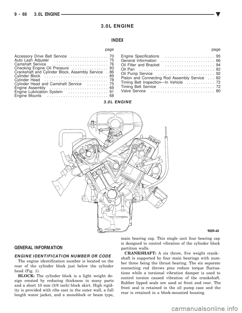
The engine identification number is located on the
rear of the cylinder block just below the cylinder
head (Fig. 1). BLOCK: The cylinder block is a light weight de-
sign created by reducing thickness in many parts
and a short 10 mm (3/8 inch) block skirt. High rigid-
ity is provided with ribs cast in the outer wall, a full
length water jacket, and a monoblock or beam type, main bearing cap. This single unit four bearing cap
is designed to control vibration of the cylinder block
partition walls.
CRANKSHAFT: A six throw, five weight crank-
shaft is supported by four main bearings with num-
ber three being the thrust bearing. The six separate
connecting rod throws pins reduce torque fluctua-
tions while a torsional vibration damper is used to
control torsion caused vibration of the crankshaft.
Rubber lipped seals are used at front and rear. The
front seal is retained in the oil pump case and the
rear is retained in a block-mounted housing.
3.0L ENGINE
9 - 66 3.0L ENGINE Ä
Page 1855 of 2438

The PCM adjusts ignition timing based on the fol-
lowing inputs.
² engine coolant temperature
² engine speed (distributor pick-up)
² manifold absolute pressure
² throttle position
The Automatic Shut Down (ASD) and Fuel Pump
relays are mounted externally, but turned on and off
by the PCM through the same circuit. The distributor pick-up signal is sent to the PCM.
If the PCM does not receive a distributor signal
within approximately one second of engine cranking,
the ASD relay and fuel pump relay are deactivated.
When these relays are deactivated, power is shut off
to the fuel injector, ignition coil, oxygen sensor heat-
ing element and fuel pump. The PCM contains a voltage converter that
changes battery voltage to a regulated 8.0 volts. The
8.0 volts power the distributor pick-up and vehicle
speed sensor. The PCM also provides a 5.0 volts sup-
ply for the coolant temperature sensor, manifold ab-
solute pressure sensor and throttle position sensor.
AIR CONDITIONING SWITCH SENSE (AA, AG, AJ
BODY)ÐPCM INPUT
When the air conditioning or defrost switch is in
the ON position and the low pressure and high pres-
sure switches are closed, the PCM receives an input
for air conditioning. After receiving this input, the
PCM activates the A/C compressor clutch by ground-
ing the A/C clutch relay. The PCM also adjusts idle
speed to a scheduled RPM to compensate for in-
creased engine load.
AIR CONDITIONING SWITCH SENSE (AC
BODY)ÐPCM INPUT
When the air conditioning or defrost switch is in
the ON position and the low pressure, high pressure
and ambient temperature switches are closed, the
PCM receives an input for air conditioning. After re-
ceiving this input, the PCM activates the A/C com-
pressor clutch by grounding the A/C clutch relay.
The PCM also adjusts idle speed to a scheduled RPM
to compensate for increased engine load.
BATTERY VOLTAGEÐPCM INPUT
The PCM monitors the battery voltage input to de-
termine fuel injector pulse width and generator field
control. If battery voltage is low, the PCM will in-
crease injector pulse width.
BRAKE SWITCHÐPCM INPUT
When the brake switch is activated, the PCM re-
ceives an input indicating that the brakes are being
applied. After receiving this input the PCM main-
tains idle speed to a scheduled RPM through the idle
air control motor. The brake switch is mounted on
the brake pedal support bracket.
ENGINE COOLANT TEMPERATURE SENSORÐPCM
INPUT
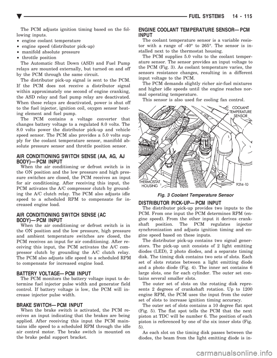
The coolant temperature sensor is a variable resis-
tor with a range of -40É to 265É. The sensor is in-
stalled next to the thermostat housing. The PCM supplies 5.0 volts to the coolant temper-
ature sensor. The sensor provides an input voltage to
the PCM (Fig. 3). As coolant temperature varies, the
sensors resistance changes, resulting in a different
input voltage to the PCM. The PCM demands slightly richer air-fuel mixtures
and higher idle speeds until the engine reaches nor-
mal operating temperature. This sensor is also used for cooling fan control.
DISTRIBUTOR PICK-UPÐPCM INPUT
The distributor pick-up provides two inputs to the
PCM. From one input the PCM determines RPM (en-
gine speed). From the other input it derives crank-
shaft position. The PCM regulates injector
synchronization and adjusts ignition timing and en-
gine speed based on these inputs. The distributor pick-up contains two signal gener-
ators. The pick-up unit consists of 2 light emitting
diodes (LED), 2 photo diodes, and a separate timing
disk. The timing disk contains two sets of slots. Each
set of slots rotates between a light emitting diode
and a photo diode (Fig. 4). The inner set contains 6
large slots, one for each cylinder. The outer set con-
tains several smaller slots. The outer set of slots on the rotating disk repre-
sents 2 degrees of crankshaft rotation. Up to 1200
engine RPM, the PCM uses the input from the outer
set of slots to increase ignition timing accuracy. The outer set of slots contains a 10 degree flat spot
(Fig. 5). The flat spot tells the PCM that the next
piston at TDC will be number 6. The position of each
piston is referenced by one of the six inner slots (Fig.
5). As each slot on the timing disk passes between the
diodes, the beam from the light emitting diode is in-
Fig. 3 Coolant Temperature Sensor
Ä FUEL SYSTEMS 14 - 115