1993 CHEVROLET PLYMOUTH ACCLAIM fuse chart
[x] Cancel search: fuse chartPage 766 of 2438
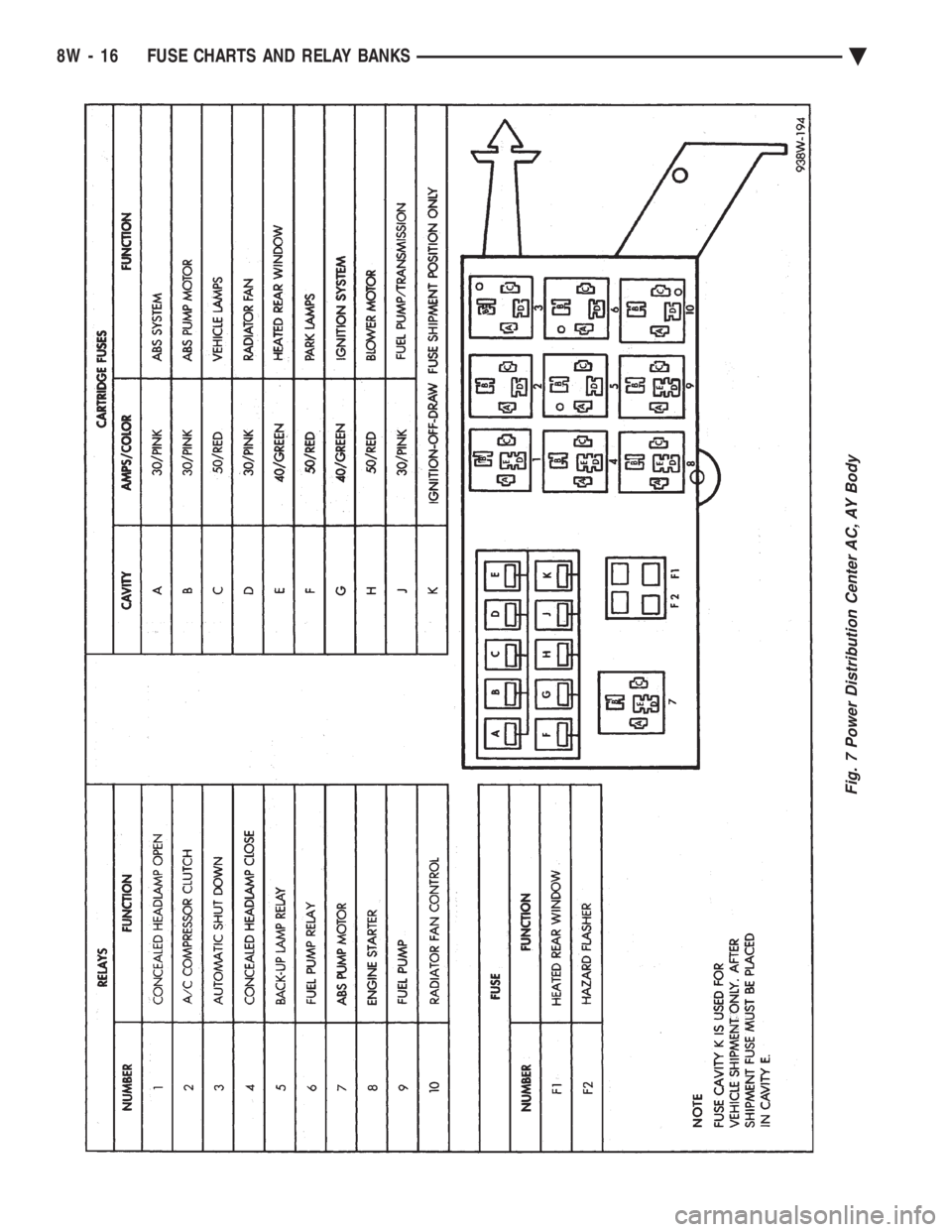
Fig. 7 Power Distribution Center AC, AY Body
8W - 16 FUSE CHARTS AND RELAY BANKS Ä
Page 767 of 2438
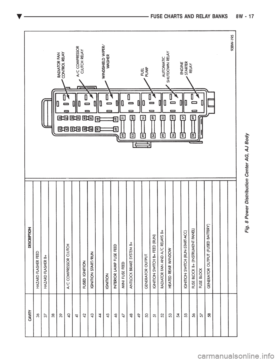
Fig. 8 Power Distribution Center AG, AJ Body
Ä FUSE CHARTS AND RELAY BANKS 8W - 17
Page 768 of 2438

8W - 18 FUSE CHARTS AND RELAY BANKS Ä
Page 932 of 2438
Wiring Diagram
Name Sheet Number
Fan Control Relay ...........................33
Radiator Fan Motor ..........................33
Fog Lamps ............................. .55, 56
Fog Lamp Relay .............................48
Fog Lamp Switch .............................48
Front End Lighting ........................ .55, 56
Front Left Side Marker Lamp ....................56
Front Right Side Marker Lamp ...................55
Left Aero Hi-Low Beam Headlamp .................56
Left Fog Lamp .............................56
Left Park & Turn Signal Lamp ...................56
Right Aero Hi-Low Beam Headlamp ................55
Right Fog Lamp ............................55
Right Park & Turn Signal Lamp ..................55
Fuel Injection Ignition System (2.5L) .......12, 13, 14, 15, 16
Automatic Shutdown Relay ......................14
Distributor ................................15
Engine Coolant Sensor ........................15
EVAP/Purge Solenoid .........................13
Exhaust Gas Recirculation Diagnostic Solenoid .........13
Heated Oxygen Sensor ........................12
Idle Air Control Motor .........................12
Ignition Coil ...............................14
Injector ..................................16
MAP Sensor ...............................13
Powertrain Control Module ............12, 13, 14, 15, 16
Throttle Position (Sensor) ......................12
Vehicle Speed Senosr .........................15
Fuel Injection Ignition System Flex Fuel (2.5L Engine) ................ .17, 18, 19, 20, 21, 22
Auto Shutdown Relay ........................20
Distributor ...............................22
Engine Coolant Sensor ........................21
EVAP/Purge Solenoid .........................19
Fuel Sensor ...............................17
Heated Oxygen Sensor ........................18
Idle Air Control Motor ........................18
Ignition Coil ...............................20
Injectors .................................17
MAP Sensor ..............................19
Powertrain Control Module (PCM) . . . .17, 18, 19, 20, 21, 22
Throttle Position (Sensor) ......................18
Vehicle Speed Sensor ........................21
Fuel Injection Ignition System (3.0L) ............. .23, 24, 25, 26, 27, 28, 29, 30, 31
Automatic Shutdown Relay .....................28
Distributor ...............................27
Engine Coolant Sensor ........................27
Exhaust Gas Recirculation Diagnostic Solenoid .........24
EVAP/Purge Solenoid .........................23
Heated Oxygen Sensor ........................24
Idle Air Control Motor ........................30
Injectors .................................26
Ignition Coil ...............................29
MAP Sensor ..............................30
Power Steering Pressure Switch ..................25Wiring Diagram
Name Sheet Number
Powertrain Control Module (PCM) .............. .23, 24, 25, 27, 28, 29, 30, 31
Throttle Position (Sensor) ......................24
Vehicle Speed Sensor ........................28
Fuel Pump Motor .............................69
Fuel Pump Relay .............................70
Fuel Tank Electrical Systems ...................69, 70
Fuel Pump Motor ...........................69
Fuel Pump Relays ...........................70
Fuel Tank Level Gauge Sending Unit ...............69
Fuse Application Chart .....................1,2,3,4
Fuses Fuse 1 ..............................4,80,84
Fuse 2 .............4,5,39,40,53,74,80,84,87,89
Fuse 3 ..............................1,95,99
Fuse 4 ..............................1,95,99
Fuse 5 ...............1,49,51,68,71,72,84,87,89
Fuse 6 ..............................2,65,89
Fuse 7 ..............................3,11,59
Fuse 8 ......................3,11,44,45,47,77
Fuse 9 .........................3,11,68,71,72
Fuse 11 ...............3,9,11,16,22,37,47,60,84
Fuse 12 ...............................1,61
Fuse 14 ...............................2,48
Fuse 15 .......................2,45,47,48,106
Fuse 16 ..........................2,44,45,59
Fuse 18 .............................4,11,64
Fuse 19 .............................4,11,61
Fuse 20 ..........................4,11,87,89
Fuseblock Module & Relay Blank ..................107
Glove Box Lamp and Switch ......................54
Hazard Flasher ..............................61
Headlamp Dimmer Switch .....................1,50
Headlamp, Key-in, Seat Belt Chimes .................45
Headlamp Optical Horn Dimmer Switch .............1,50
Headlamp Switch ...........................1,49
Headlamp and Fog Lamp Switch ..............48, 49, 50
Fog Lamp Relay ............................48
Fog Lamp Switch ...........................48
Headlamp Switch ...........................49
Optical Horn & Headlamp Dimmer Switch ............50
Headlamp Switch Controlled Interior Lighting .........51, 52
A/C Lamps ...............................52
Ash Receiver Lamp ..........................52
Cigar Lighter Lamp ..........................52
Heater Lamp ..............................52
Radio Lamp ...............................52
Heated Oxygen Sensor ................... .12, 18, 24
Heated Rear Window ..........................84
Heated Rear Window .........................84
Switch ..................................84
Timer ...................................84
Heater System ...............................68
Bi-level Control Switch ........................68
Blower Motor ..............................68
Blower Slide Control .........................68
Heater Control Switch ........................68
8W - 182 WIRING DIAGRAMS AA-BODY Ä
Page 1066 of 2438
Wiring Diagram
Name Sheet Number
Left Cornering Lamp .........................82
Left High Beam Headlamp ......................82
Left Low Beam Headlamp ......................82
Left Park/Turn Signal Lamp .....................82
Left Side Marker Lamp ........................82
Right Cornering Lamp ........................81
Right High Beam Headlamp .....................81
Right Low Beam Headlamp .....................81
Right Park/Turn Signal Lamp ....................81
Right Side Marker Lamp .......................81
Front End Lighting Concealed Headlamps with D.R.L. (New Yorker/5th Avenue) ................... .83, 84
Daytime Running Lamp Module ..................84
Left Cornering Lamp .........................84
Left High Beam Headlamp ......................84
Left Low Beam Headlamp ......................84
Left Park/Turn Signal Lamp .....................84
Left Side Marker Lamp ........................84
Right Cornering Lamp ........................83
Right High Beam Headlamp .....................83
Right Low Beam Headlamp .....................83
Right Park/Turn Signal Lamp ....................83
Right Side Marker Lamp .......................83
Fuel Injection Ignition System (3.0L) ......19, 20, 21, 22, 23
Automatic Shut Down Relay ....................23
Data Link Connector .........................23
Distributor ...............................19
Distributor Ignition Coil .......................23
Engine Coolant Temperature Sensor ...............19
EVAP/Purge Solenoid .........................20
Exhaust Gas Recirculation Solenoid ................21
Heated Oxygen Sensor ........................19
Idle Air Control Motor ........................21
Injectors .................................20
MAP Sensor ..............................21
Power Steering Switch ........................19
Powertrain Control Module ...........19, 20, 21, 22, 23
Throttle Position (Sensor) ......................21
Fuel Injection Ignition System (3.3L & 3.8L) .............. .24, 25, 26, 27, 28, 29
Automatic Shut Down Relay ....................29
Camshaft Position Sensor ......................28
Crankshaft Position Sensor .....................28
Data Link Connector .........................29
Direct Ignition System Coil Pack ..................24
Engine Coolant Temperature Sensor ...............25
EVAP/Purge Solenoid .........................27
Exhaust Gas Recirculation Solenoid ................26
Heated Oxygen Sensor ........................25
Idle Air Control Motor ........................26
Injectors .................................24
MAP Sensor ..............................26
Power Steering Switch ........................25
Powertrain Control Module .........24, 25, 26, 27, 28, 29
Throttle Position (Sensor) ......................26
Fuel Pump Motor .............................36
Fuel Pump Relay .............................36Wiring Diagram
Name Sheet Number
Fuel Tank Level Gauge Sending Unit .................36
Fuse Application Chart .....................1,2,3,4
Fuseblock Module ........................... .168
Fuses Fuse #1 ...............................2,66
Fuse #2 ........................2,37,43,59,66
Fuse #3 .............1,66,69,71,73,75,78,81,83,
96, 102, 105, 110
Fuse #4 .............1,66,69,71,73,75,78,81,83,
96, 102, 105, 110
Fuse #5 ................1,51,53,55,65,85,95,99,
101, 116, 119, 121, 128, 132, 136, 148
Fuse #6 .....................4,11,15,22,27,37
Fuse #7 ..................4,11,15,22,27,41,147
Fuse #8 . . .4, 11, 15, 22, 27, 57, 67, 95, 100, 102, 104, 107, 109, 128, 132, 135, 141
Fuse #9 ............3,11,57, 115, 124, 125, 148, 158
Fuse #10 ....................3,11,51,53,55,115
Fuse #11 .......................3,11,12,33,53
Fuse #12 ...................... .88, 91, 112, 159
Fuse #13 ...........................4,99,159
Fuse #14 ...............................1,64
Fuse #15 ...........2,6,7,9,57,64, 118, 126, 128, 1
32, 136, 139, 151, 160
Fuse #16 ..............................2,122
Fuse #17 .......................4, 143, 146, 148
Fuse #18 ........3,11,62, 103, 106, 108, 130, 134, 137
Fuse #19 ............................3,11,59
Fuse #20 .....................3,11, 119, 121, 126
Fuse F1-Power Distribution Center .........4,5,7,9,148
Fuse F2-Hazard Lamp ......................5,7,9
Generator ..............................6,8,10
Glove Box Module and Front Cigar Lighter ............111
Ash Receiver Lamp ........................ .111
Deck Lid Release Switch ..................... .111
Front Cigar Lighter ........................ .111
Glove Box Lamp and Switch ...................111
Hazard Flasher ..............................59
Headlamp Dimmer Switch .....................1,66
Headlamp Switch .........................1,65,66
Optical Horn/Headlamp Dimmer Switch .............66
Headlamps-Aero ..................... .69, 70, 71, 72
Headlamps-Concealed . . .73, 74, 75, 76, 77, 78, 79, 80, 81, 82, 83, 84
Headlamp Switch Controlled Interior Lighting ...........85
Headlamp Switch Lamp .......................85
Transmission Range Lamp with Electronic Cluster .......85
Heated Oxygen Sensor ................... .14, 19, 25
Heated Rear Window ......................... .148
Heated Rear Window Switch ...................148
Rear Window Grid ......................... .148
Heated Rear Window Switch ...................4,148
Heater Bi-Lever Control Switch ....................51
Heater Blower Motor ...........................51
Heater Blower Motor Resistor .....................51
Heater System ...............................51
Bi-level Control Switch ........................51
Blower Motor ..............................51
8W - 316 WIRING DIAGRAMS AC-AY BODY Ä
Page 1284 of 2438
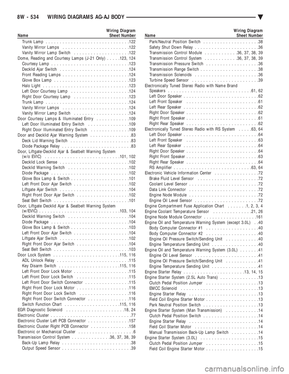
Wiring Diagram
Name Sheet Number
Trunk Lamp ............................. .122
Vanity Mirror Lamps ....................... .122
Vanity Mirror Lamp Switch ................... .122
Dome, Reading and Courtesy Lamps (J-21 Only) .....123, 124
Courtesy Lamp ........................... .123
Decklid Ajar Switch ........................ .124
Front Reading Lamps ....................... .124
Glove Box Lamp .......................... .123
Halo Light .............................. .123
Left Door Courtesy Lamp .................... .124
Right Door Courtesy Lamp ................... .123
Trunk Lamp ............................. .124
Vanity Mirror Lamps ....................... .124
Vanity Mirror Lamp Switch ................... .124
Door Courtesy Lamps & Illuminated Entry ............109
Left Door Illuminated Entry Switch ...............109
Right Door Illuminated Entry Switch ..............109
Door and Decklid Ajar Warning System ...............83
Deck Lid Warning Switch ......................83
Diode Package Relay .........................83
Door, Liftgate-Decklid Ajar & Seatbelt Warning System (w/o EVIC) .......................... .101, 102
Decklid Lock Sense ........................ .102
Decklid Warning Switch ..................... .102
Diode Package ........................... .102
Glove Box Lamp & Switch .................... .101
Left Front Door Ajar Switch ................... .102
Liftgate Ajar Switch ........................ .104
Right Front Door Ajar Switch ...................102
Seat Belt Switch .......................... .101
Door, Liftgate Decklid Ajar & Seatbelt Warning System (w/EVIC) ............................ .103, 104
Decklid Warning Switch ..................... .104
Diode Package ........................... .104
Glove Box Lamp & Switch .................... .103
Left Front Door Ajar Switch ................... .104
Liftgate Ajar Switch ........................ .102
Right Front Door Ajar Switch ...................104
Seat Belt Switch .......................... .103
Door Lock System ....................... .115, 116
ADL Unlock Relay ......................... .115
Key Disarm Switch ..................... .115, 116
Left Front Door Lock Motor ................... .115
Left Front Door Lock Switch ...................115
Left Front Door Switch Connector ................115
Right Front Door Lock Motor ...................116
Right Front Door Lock Switch ..................116
Right Front Door Switch Connector ...............116
Switch Function Chart ................... .115, 116
EGR Diagnostic Solenoid .................... .18, 24
Electronic Cluster .............................77
Electronic Cluster Left PCB Connector ...............157
Electronic Cluster Right PCB Connector ..............158
Electronic or Mechanical Cluster ....................6
Transmission Control System ..............36, 37, 38, 39
Back-Up Lamp Relay .........................38
Output Speed Sensor .........................39Wiring Diagram
Name Sheet Number
Park/Neutral Position Switch ....................38
Safety Shut Down Relay .......................36
Transmission Control Module ............36, 37, 38, 39
Transmission Control System ............36, 37, 38, 39
Transmission Pressure Switch ...................36
Transmission Range Switch .....................38
Transmission Solenoids .......................36
Turbine Speed Sensor ........................39
Electronically Tuned Stereo Radio with Name Brand Speakers ............................. .61, 62
Left Door Speaker ...........................62
Left Front Speaker ..........................61
Left Rear Speaker ...........................62
Right Door Speaker ..........................62
Right Front Speaker ..........................61
Right Rear Speaker ..........................62
Electronically Tuned Stereo Radio with RS System .....63, 64
Left Door Speaker ...........................64
Left Front Speaker ..........................63
Left Rear Speaker ...........................64
Right Door Speaker ..........................64
Right Front Speaker ..........................63
Right Rear Speaker ..........................64
RS Amplifier ........................... .63, 64
Electronic Vehicle Information Center ................72
Brake Fluid Level Sensor ......................72
Coolant Level Sensor .........................72
Data Link Connector .........................72
Engine Node Module .........................72
Engine Oil Level Sensor .......................72
Engine Compartment Fuse Application Chart .......1,2,3,4
Engine Coolant Temperature Sensor ..............21, 26
Engine Node Module Connector ...................161
Engine Oil and Temperature Warning System (except 3.0L) . .40 Body Computer Connector #1 ...................40
Body Computer Connector #2 ...................40
Engine Oil Pressure Switch/Sending Unit ............40
Engine Temperature Sending Unit .................40
Engine Oil and Temperature Warning System (3.0L) .......41
Engine Oil Level Sensor .......................41
Engine Oil Pressure Switch/Sending Unit ............41
Engine Temperature Sending Unit .................41
Engine Starter Relay ..................... .13, 14, 15
Engine Starter System (2.5L Auto Trans) ..............13
Clutch Pedal Position Jumper ...................13
EMCC Solenoid ............................13
Engine Starter Relay .........................13
Field Coil Engine Starter Motor ...................13
Park Neutral Position Switch ....................13
Engine Starter System (Man Transmission) ............14
Clutch Pedal Position Switch ....................14
Engine Starter Relay .........................14
Field Coil Starter Motor .......................14
Manual Transmission Back-Up Lamp Switch ..........14
Engine Starter System (3.0L) .....................15
Clutch Pedal Position Jumper ...................15
Field Coil Engine Starter Motor ...................15
8W - 534 WIRING DIAGRAMS AG-AJ BODY Ä
Page 1286 of 2438
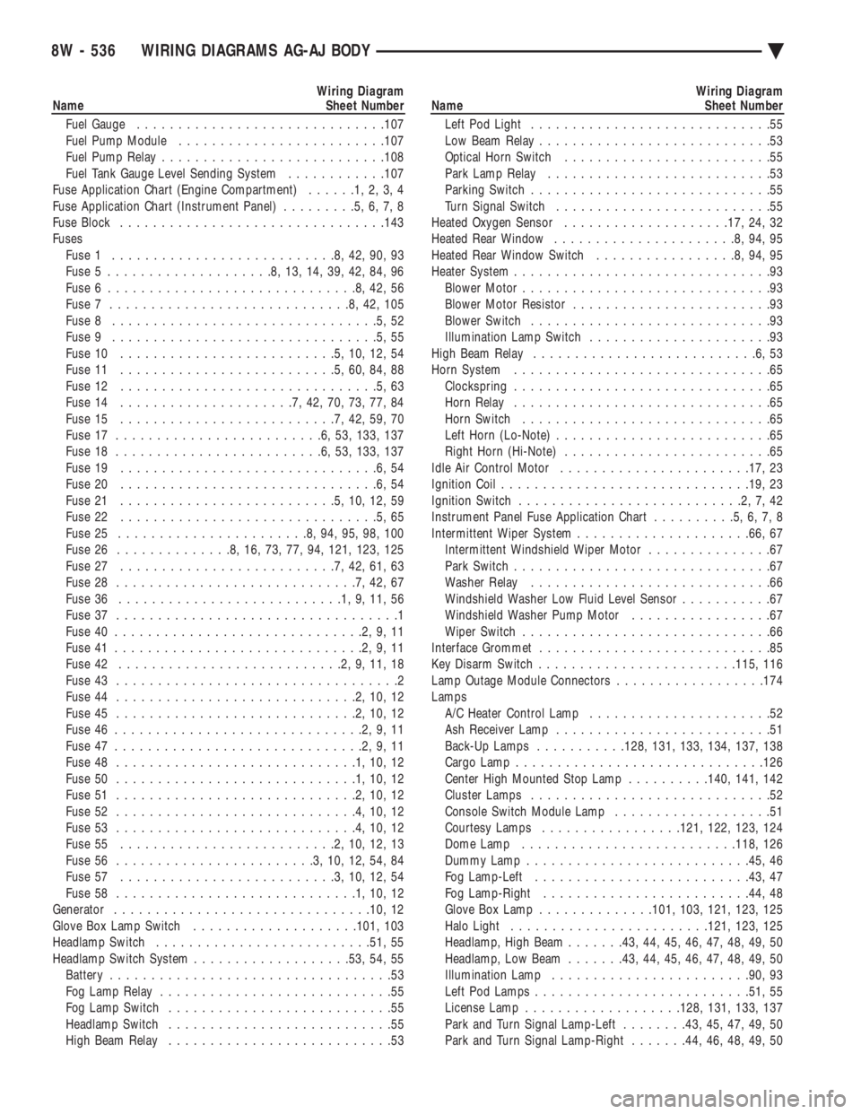
Wiring Diagram
Name Sheet Number
Fuel Gauge ............................. .107
Fuel Pump Module ........................ .107
Fuel Pump Relay .......................... .108
Fuel Tank Gauge Level Sending System ............107
Fuse Application Chart (Engine Compartment) ......1,2,3,4
Fuse Application Chart (Instrument Panel) .........5,6,7,8
Fuse Block ............................... .143
Fuses Fuse 1 ...........................8,42,90,93
Fuse 5 ....................8,13,14,39,42,84,96
Fuse 6 ..............................8,42,56
Fuse 7 .............................8,42,105
Fuse 8 ................................5,52
Fuse 9 ................................5,55
Fuse 10 ..........................5,10,12,54
Fuse 11 ..........................5,60,84,88
Fuse 12 ...............................5,63
Fuse 14 .....................7,42,70,73,77,84
Fuse 15 ..........................7,42,59,70
Fuse 17 .........................6,53, 133, 137
Fuse 18 .........................6,53, 133, 137
Fuse 19 ...............................6,54
Fuse 20 ...............................6,54
Fuse 21 ..........................5,10,12,59
Fuse 22 ...............................5,65
Fuse 25 .......................8,94,95,98,100
Fuse 26 ..............8,16,73,77,94, 121, 123, 125
Fuse 27 ..........................7,42,61,63
Fuse 28 .............................7,42,67
Fuse 36 ...........................1,9,11,56
Fuse 37 ..................................1
Fuse 40 ..............................2,9,11
Fuse 41 ..............................2,9,11
Fuse 42 ...........................2,9,11,18
Fuse 43 ..................................2
Fuse 44 .............................2,10,12
Fuse 45 .............................2,10,12
Fuse 46 ..............................2,9,11
Fuse 47 ..............................2,9,11
Fuse 48 .............................1,10,12
Fuse 50 .............................1,10,12
Fuse 51 .............................2,10,12
Fuse 52 .............................4,10,12
Fuse 53 .............................4,10,12
Fuse 55 ..........................2,10,12,13
Fuse 56 ........................3,10,12,54,84
Fuse 57 ..........................3,10,12,54
Fuse 58 .............................1,10,12
Generator .............................. .10, 12
Glove Box Lamp Switch ................... .101, 103
Headlamp Switch ......................... .51, 55
Headlamp Switch System .................. .53, 54, 55
Battery ..................................53
Fog Lamp Relay ............................55
Fog Lamp Switch ...........................55
Headlamp Switch ...........................55
High Beam Relay ...........................53Wiring Diagram
Name Sheet Number
Left Pod Light .............................55
Low Beam Relay ............................53
Optical Horn Switch .........................55
Park Lamp Relay ...........................53
Parking Switch .............................55
Turn Signal Switch ..........................55
Heated Oxygen Sensor ................... .17, 24, 32
Heated Rear Window ......................8,94,95
Heated Rear Window Switch .................8,94,95
Heater System ...............................93
Blower Motor ..............................93
Blower Motor Resistor ........................93
Blower Switch .............................93
Illumination Lamp Switch ......................93
High Beam Relay ...........................6,53
Horn System ...............................65
Clockspring ...............................65
Horn Relay ...............................65
Horn Switch ..............................65
Left Horn (Lo-Note) ..........................65
Right Horn (Hi-Note) .........................65
Idle Air Control Motor ...................... .17, 23
Ignition Coil ............................. .19, 23
Ignition Switch ...........................2,7,42
Instrument Panel Fuse Application Chart ..........5,6,7,8
Intermittent Wiper System .................... .66, 67
Intermittent Windshield Wiper Motor ...............67
Park Switch ...............................67
Washer Relay .............................66
Windshield Washer Low Fluid Level Sensor ...........67
Windshield Washer Pump Motor .................67
Wiper Switch ..............................66
Interface Grommet ............................85
Key Disarm Switch ....................... .115, 116
Lamp Outage Module Connectors ..................174
Lamps A/C Heater Control Lamp ......................52
Ash Receiver Lamp ..........................51
Back-Up Lamps ...........128, 131, 133, 134, 137, 138
Cargo Lamp ............................. .126
Center High Mounted Stop Lamp ..........140, 141, 142
Cluster Lamps .............................52
Console Switch Module Lamp ...................51
Courtesy Lamps ................ .121, 122, 123, 124
Dome Lamp ......................... .118, 126
Dummy Lamp .......................... .45, 46
Fog Lamp-Left ......................... .43, 47
Fog Lamp-Right ........................ .44, 48
Glove Box Lamp ............. .101, 103, 121, 123, 125
Halo Light ....................... .121, 123, 125
Headlamp, High Beam .......43, 44, 45, 46, 47, 48, 49, 50
Headlamp, Low Beam .......43, 44, 45, 46, 47, 48, 49, 50
Illumination Lamp ....................... .90, 93
Left Pod Lamps ......................... .51, 55
License Lamp .................. .128, 131, 133, 137
Park and Turn Signal Lamp-Left ........43, 45, 47, 49, 50
Park and Turn Signal Lamp-Right .......44, 46, 48, 49, 50
8W - 536 WIRING DIAGRAMS AG-AJ BODY Ä
Page 2377 of 2438
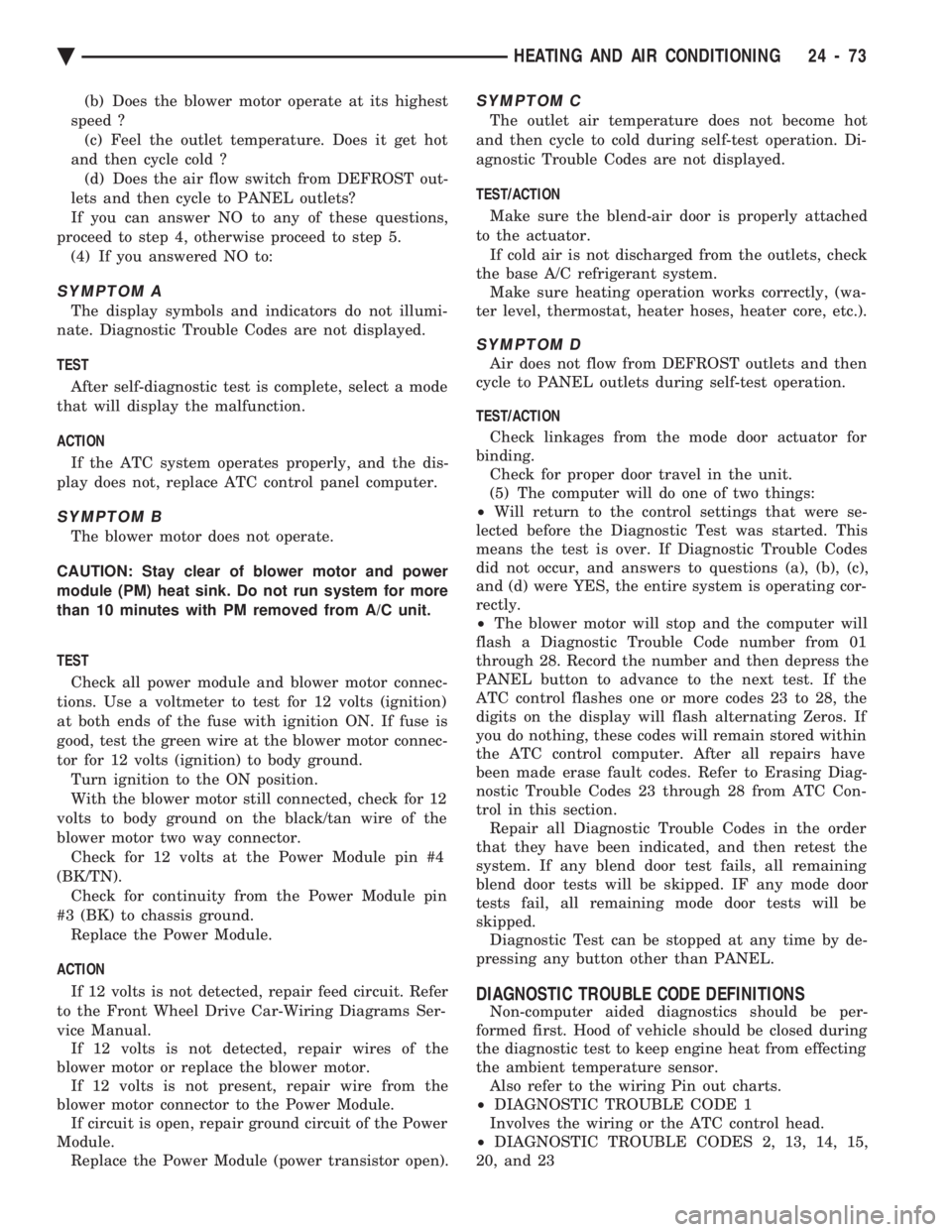
(b) Does the blower motor operate at its highest
speed ? (c) Feel the outlet temperature. Does it get hot
and then cycle cold ? (d) Does the air flow switch from DEFROST out-
lets and then cycle to PANEL outlets?
If you can answer NO to any of these questions,
proceed to step 4, otherwise proceed to step 5. (4) If you answered NO to:
SYMPTOM A
The display symbols and indicators do not illumi-
nate. Diagnostic Trouble Codes are not displayed.
TEST
After self-diagnostic test is complete, select a mode
that will display the malfunction.
ACTION
If the ATC system operates properly, and the dis-
play does not, replace ATC control panel computer.
SYMPTOM B
The blower motor does not operate.
CAUTION: Stay clear of blower motor and power
module (PM) heat sink. Do not run system for more
than 10 minutes with PM removed from A/C unit.
TEST Check all power module and blower motor connec-
tions. Use a voltmeter to test for 12 volts (ignition)
at both ends of the fuse with ignition ON. If fuse is
good, test the green wire at the blower motor connec-
tor for 12 volts (ignition) to body ground. Turn ignition to the ON position.
With the blower motor still connected, check for 12
volts to body ground on the black/tan wire of the
blower motor two way connector. Check for 12 volts at the Power Module pin #4
(BK/TN). Check for continuity from the Power Module pin
#3 (BK) to chassis ground. Replace the Power Module.
ACTION If 12 volts is not detected, repair feed circuit. Refer
to the Front Wheel Drive Car-Wiring Diagrams Ser-
vice Manual. If 12 volts is not detected, repair wires of the
blower motor or replace the blower motor. If 12 volts is not present, repair wire from the
blower motor connector to the Power Module. If circuit is open, repair ground circuit of the Power
Module. Replace the Power Module (power transistor open).
SYMPTOM C
The outlet air temperature does not become hot
and then cycle to cold during self-test operation. Di-
agnostic Trouble Codes are not displayed.
TEST/ACTION
Make sure the blend-air door is properly attached
to the actuator. If cold air is not discharged from the outlets, check
the base A/C refrigerant system. Make sure heating operation works correctly, (wa-
ter level, thermostat, heater hoses, heater core, etc.).
SYMPTOM D
Air does not flow from DEFROST outlets and then
cycle to PANEL outlets during self-test operation.
TEST/ACTION Check linkages from the mode door actuator for
binding. Check for proper door travel in the unit.
(5) The computer will do one of two things:
² Will return to the control settings that were se-
lected before the Diagnostic Test was started. This
means the test is over. If Diagnostic Trouble Codes
did not occur, and answers to questions (a), (b), (c),
and (d) were YES, the entire system is operating cor-
rectly.
² The blower motor will stop and the computer will
flash a Diagnostic Trouble Code number from 01
through 28. Record the number and then depress the
PANEL button to advance to the next test. If the
ATC control flashes one or more codes 23 to 28, the
digits on the display will flash alternating Zeros. If
you do nothing, these codes will remain stored within
the ATC control computer. After all repairs have
been made erase fault codes. Refer to Erasing Diag-
nostic Trouble Codes 23 through 28 from ATC Con-
trol in this section. Repair all Diagnostic Trouble Codes in the order
that they have been indicated, and then retest the
system. If any blend door test fails, all remaining
blend door tests will be skipped. IF any mode door
tests fail, all remaining mode door tests will be
skipped. Diagnostic Test can be stopped at any time by de-
pressing any button other than PANEL.
DIAGNOSTIC TROUBLE CODE DEFINITIONS
Non-computer aided diagnostics should be per-
formed first. Hood of vehicle should be closed during
the diagnostic test to keep engine heat from effecting
the ambient temperature sensor. Also refer to the wiring Pin out charts.
² DIAGNOSTIC TROUBLE CODE 1
Involves the wiring or the ATC control head.
² DIAGNOSTIC TROUBLE CODES 2, 13, 14, 15,
20, and 23
Ä HEATING AND AIR CONDITIONING 24 - 73