1993 CHEVROLET PLYMOUTH ACCLAIM wiring diagram
[x] Cancel search: wiring diagramPage 1471 of 2438
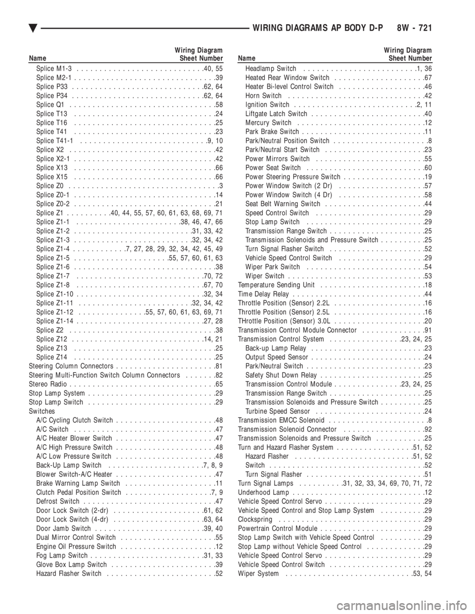
Wiring Diagram
Name Sheet Number
Splice M1-3 ........................... .40, 55
Splice M2-1 ...............................39
Splice P33 ............................ .62, 64
Splice P34 ............................ .62, 64
Splice Q1 ................................58
Splice T13 ...............................24
Splice T16 ...............................25
Splice T41 ...............................23
Splice T41-1 ............................9,10
Splice X2 ................................42
Splice X2-1 ...............................42
Splice X13 ...............................66
Splice X15 ...............................66
Splice Z0 .................................3
Splice Z0-1 ...............................14
Splice Z0-2 ...............................21
Splice Z1 ......... .40, 44, 55, 57, 60, 61, 63, 68, 69, 71
Splice Z1-1 ...................... .38, 46, 47, 66
Splice Z1-2 ......................... .31, 33, 42
Splice Z1-3 ......................... .32, 34, 42
Splice Z1-4 ............7,27,28,29,32,34,42,45,49
Splice Z1-5 .................... .55, 57, 60, 61, 63
Splice Z1-6 ...............................38
Splice Z1-7 ........................... .70, 72
Splice Z1-8 ........................... .67, 70
Splice Z1-10 ........................... .32, 34
Splice Z1-11 ........................ .32, 34, 42
Splice Z1-12 .............. .55, 57, 60, 61, 63, 69, 71
Splice Z1-14 ........................... .27, 28
Splice Z2 ................................38
Splice Z12 ............................ .14, 21
Splice Z13 ...............................25
Splice Z14 ...............................25
Steering Column Connectors ......................81
Steering Multi-Function Switch Column Connectors .......82
Stereo Radio ................................65
Stop Lamp System ............................29
Stop Lamp Switch ............................29
Switches A/C Cycling Clutch Switch ......................48
A/C Switch ...............................47
A/C Heater Blower Switch ......................47
A/C High Pressure Switch ......................48
A/C Low Pressure Switch ......................48
Back-Up Lamp Switch .....................7,8,9
Blower Switch-A/C Heater ......................47
Brake Warning Lamp Switch ....................11
Clutch Pedal Position Switch ...................7,9
Defrost Switch .............................47
Door Lock Switch (2-dr) ................... .61, 62
Door Lock Switch (4-dr) ................... .63, 64
Door Jamb Switch ....................... .39, 40
Dual Mirror Control Switch .....................55
Engine Oil Pressure Switch .....................12
Fog Lamp Switch ........................ .31, 33
Glove Box Lamp Switch .......................39
Hazard Flasher Switch ........................52Wiring Diagram
Name Sheet Number
Headlamp Switch .........................1,36
Heated Rear Window Switch ....................67
Heater Bi-level Control Switch ...................46
Horn Switch ..............................42
Ignition Switch ...........................2,11
Liftgate Latch Switch .........................40
Mercury Switch ............................12
Park Brake Switch ...........................11
Park/Neutral Position Switch .....................8
Park/Neutral Start Switch ......................23
Power Mirrors Switch ........................55
Power Seat Switch ..........................60
Power Steering Pressure Switch ..................19
Power Window Switch (2 Dr) ...................57
Power Window Switch (4 Dr) ...................58
Seat Belt Warning Switch ......................44
Speed Control Switch ........................29
Stop Lamp Switch ..........................29
Transmission Range Switch .....................25
Transmission Solenoids and Pressure Switch ..........25
Turn Signal Flasher Switch .....................52
Vehicle Speed Control Switch ...................29
Wiper Park Switch ..........................54
Wiper Switch ..............................53
Temperature Sending Unit .......................18
Time Delay Relay .............................44
Throttle Position (Sensor) 2.2L ....................16
Throttle Position (Sensor) 2.5L ....................16
THrottle Position (Sensor) 3.0L ....................20
Transmission Control Module Connector ..............91
Transmission Control System ................23, 24, 25
Back-up Lamp Relay .........................23
Output Speed Sensor .........................24
Park/Neutral Switch ..........................23
Safety Shut Down Relay .......................25
Transmission Control Module ...............23, 24, 25
Transmission Range Switch .....................25
Transmission Solenoids and Pressure Switch ..........25
Turbine Speed Sensor ........................24
Transmission EMCC Solenoid ......................8
Transmission Solenoid Connector ..................92
Transmission Solenoids and Pressure Switch ...........25
Turn and Hazard Flasher System .................51, 52
Hazard Flasher ......................... .51, 52
Switch ..................................52
Turn Signal Flasher ..........................51
Turn Signal Lamps ..........31, 32, 33, 34, 69, 70, 71, 72
Underhood Lamp .............................12
Vehicle Speed Control Servo ......................29
Vehicle Speed Control and Stop Lamp System ..........29
Clockspring ................................29
Powertrain Control Module .......................29
Stop Lamp Switch with Vehicle Speed Control ..........29
Stop Lamp without Vehicle Speed Control .............29
Vehicle Speed Control Servo ......................29
Vehicle Speed Control Switch .....................29
Wiper System ........................... .53, 54
Ä WIRING DIAGRAMS AP BODY D-P 8W - 721
Page 1472 of 2438
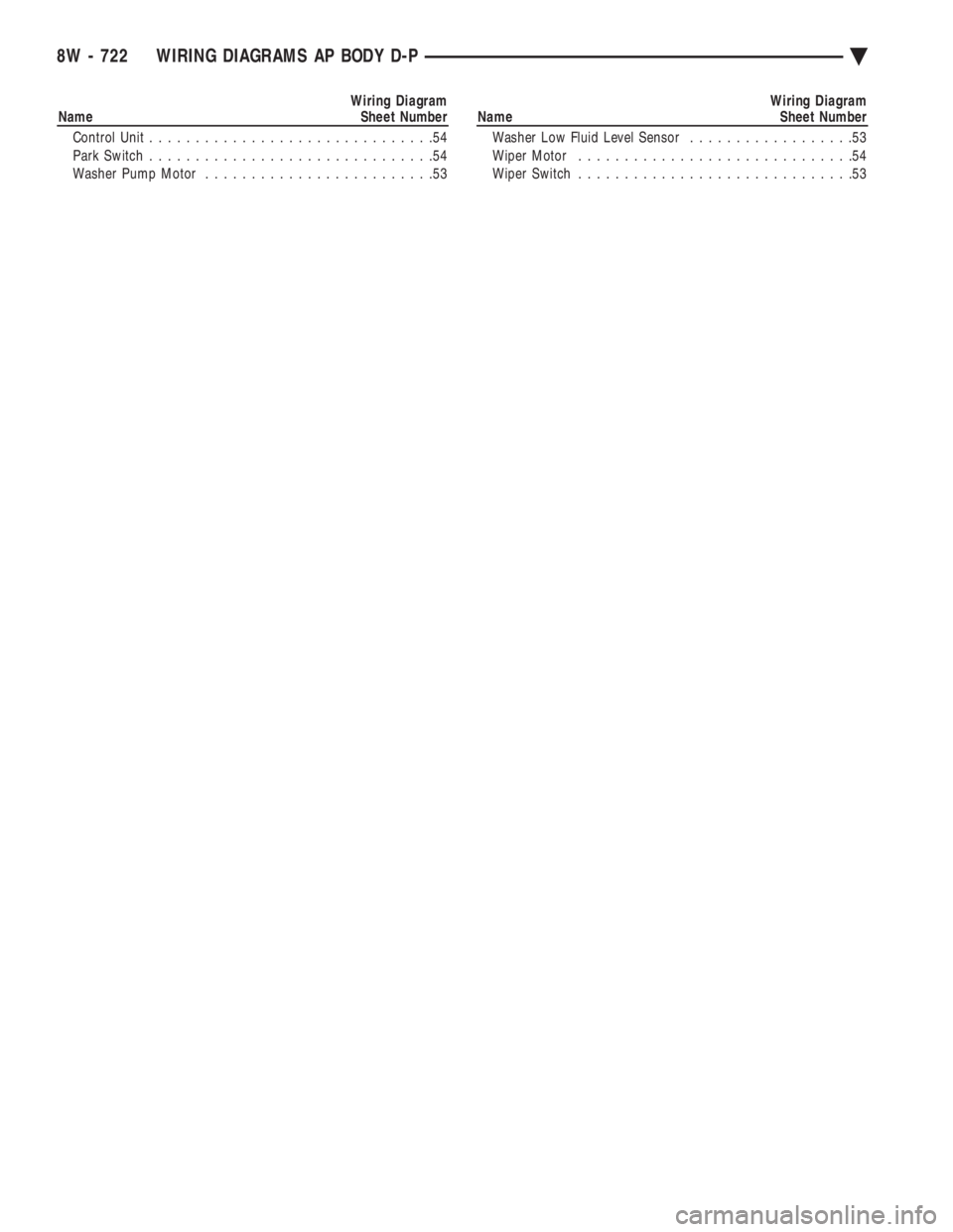
Wiring Diagram
Name Sheet Number
Control Unit ...............................54
Park Switch ...............................54
Washer Pump Motor .........................53Wiring Diagram
Name Sheet Number
Washer Low Fluid Level Sensor ..................53
Wiper Motor ..............................54
Wiper Switch ..............................53
8W - 722 WIRING DIAGRAMS AP BODY D-P Ä
Page 1473 of 2438

Ä WIRING DIAGRAMS AP BODY D-P 8W - 723
Page 1758 of 2438
INSTALLATION
WARNING: FUEL TANKS DESIGNED FOR GASO-
LINE ONLY VEHICLES CANNOT BE USED ON
FLEXIBLE FUEL AA-BODY VEHICLES. WHEN SER-
VICING THE FUEL SYSTEM OF A FLEXIBLE FUEL
VEHICLE, ONLY USE ORIGINAL EQUIPMENT OR
EQUIVALENT REPLACEMENT COMPONENTS. (1) Position fuel tank on transmission jack. Con-
nect vapor separator/rollover valve hose and position
insulator pad on fuel tank. Position vapor vent so
that it is not pinched between tank and floor pan
during installation. (2) Raise tank and fuel filler tube carefully into
position. Use a light coating of power steering fluid
to ease fuel filler tube installation. Ensure filler tube
grommet is not damaged. Verify that the tube is in-
stalled correctly. (3) Tighten fuel tank strap nuts to 23 N Im (250 in.
lbs.) torque. Remove transmission jack. Ensure
straps are not twisted or bent. (4) Lubricate the metal tubes on the fuel pump
with clean 30 weight engine oil. Install the quick
connect fuel fittings. Refer to Quick Connect Fittings
in the Fuel Delivery section of this Group. (5) Attach electrical connector to fuel pump mod-
ule and level sensor unit. (6) Lower the vehicle.
(7) Attach filler tube to filler neck opening in
quarter panel. Tighten quarter panel screws to 2
N Im (17 in. lbs.) torque.
(8) Fill fuel tank, install filler cap, and connect
battery cable.
CAUTION: When using the ASD Fuel System Test,
the Auto Shutdown (ASD) Relay remains energized
for either 7 minutes, until the test is stopped, or un-
til the ignition switch is turned to the Off position.
(9) Use the DRBII scan tool ASD Fuel System Test
to pressurize the fuel system. Check for leaks.
FUEL PUMP MODULE
Refer to the Fuel Delivery section of this group.
METHANOL CONCENTRATION SENSOR
Refer to the Fuel Delivery section of this group.
FUEL RESERVOIR
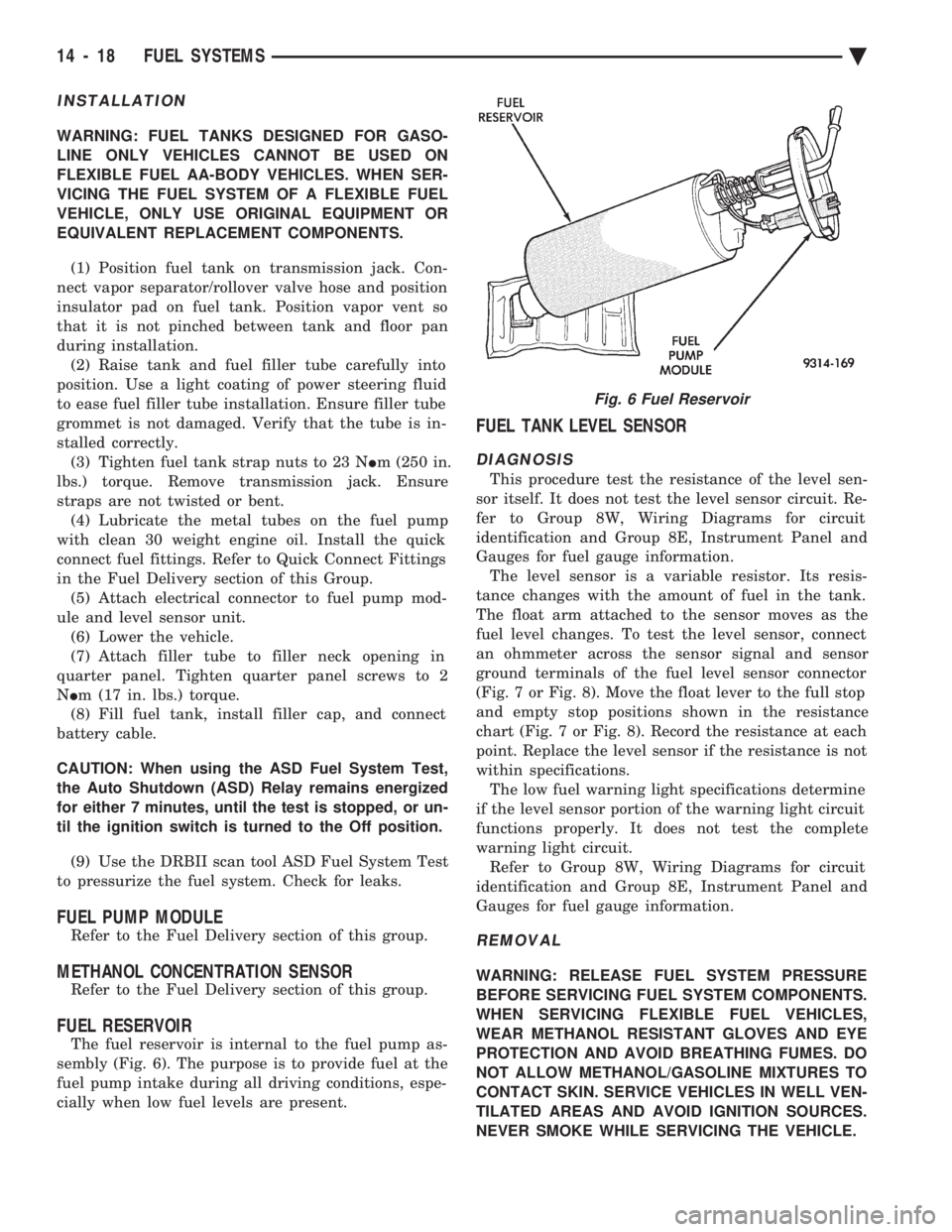
The fuel reservoir is internal to the fuel pump as-
sembly (Fig. 6). The purpose is to provide fuel at the
fuel pump intake during all driving conditions, espe-
cially when low fuel levels are present.
FUEL TANK LEVEL SENSOR
DIAGNOSIS
This procedure test the resistance of the level sen-
sor itself. It does not test the level sensor circuit. Re-
fer to Group 8W, Wiring Diagrams for circuit
identification and Group 8E, Instrument Panel and
Gauges for fuel gauge information. The level sensor is a variable resistor. Its resis-
tance changes with the amount of fuel in the tank.
The float arm attached to the sensor moves as the
fuel level changes. To test the level sensor, connect
an ohmmeter across the sensor signal and sensor
ground terminals of the fuel level sensor connector
(Fig. 7 or Fig. 8). Move the float lever to the full stop
and empty stop positions shown in the resistance
chart (Fig. 7 or Fig. 8). Record the resistance at each
point. Replace the level sensor if the resistance is not
within specifications. The low fuel warning light specifications determine
if the level sensor portion of the warning light circuit
functions properly. It does not test the complete
warning light circuit. Refer to Group 8W, Wiring Diagrams for circuit
identification and Group 8E, Instrument Panel and
Gauges for fuel gauge information.
REMOVAL
WARNING: RELEASE FUEL SYSTEM PRESSURE
BEFORE SERVICING FUEL SYSTEM COMPONENTS.
WHEN SERVICING FLEXIBLE FUEL VEHICLES,
WEAR METHANOL RESISTANT GLOVES AND EYE
PROTECTION AND AVOID BREATHING FUMES. DO
NOT ALLOW METHANOL/GASOLINE MIXTURES TO
CONTACT SKIN. SERVICE VEHICLES IN WELL VEN-
TILATED AREAS AND AVOID IGNITION SOURCES.
NEVER SMOKE WHILE SERVICING THE VEHICLE.
Fig. 6 Fuel Reservoir
14 - 18 FUEL SYSTEMS Ä
Page 1806 of 2438
2.5L FLEXIBLE FUEL MULTI-PORT FUEL INJECTIONÐGENERAL DIAGNOSIS INDEX
page page
Fuel System Diagram ..................... 66 Visual Inspection......................... 66
FUEL SYSTEM DIAGRAM
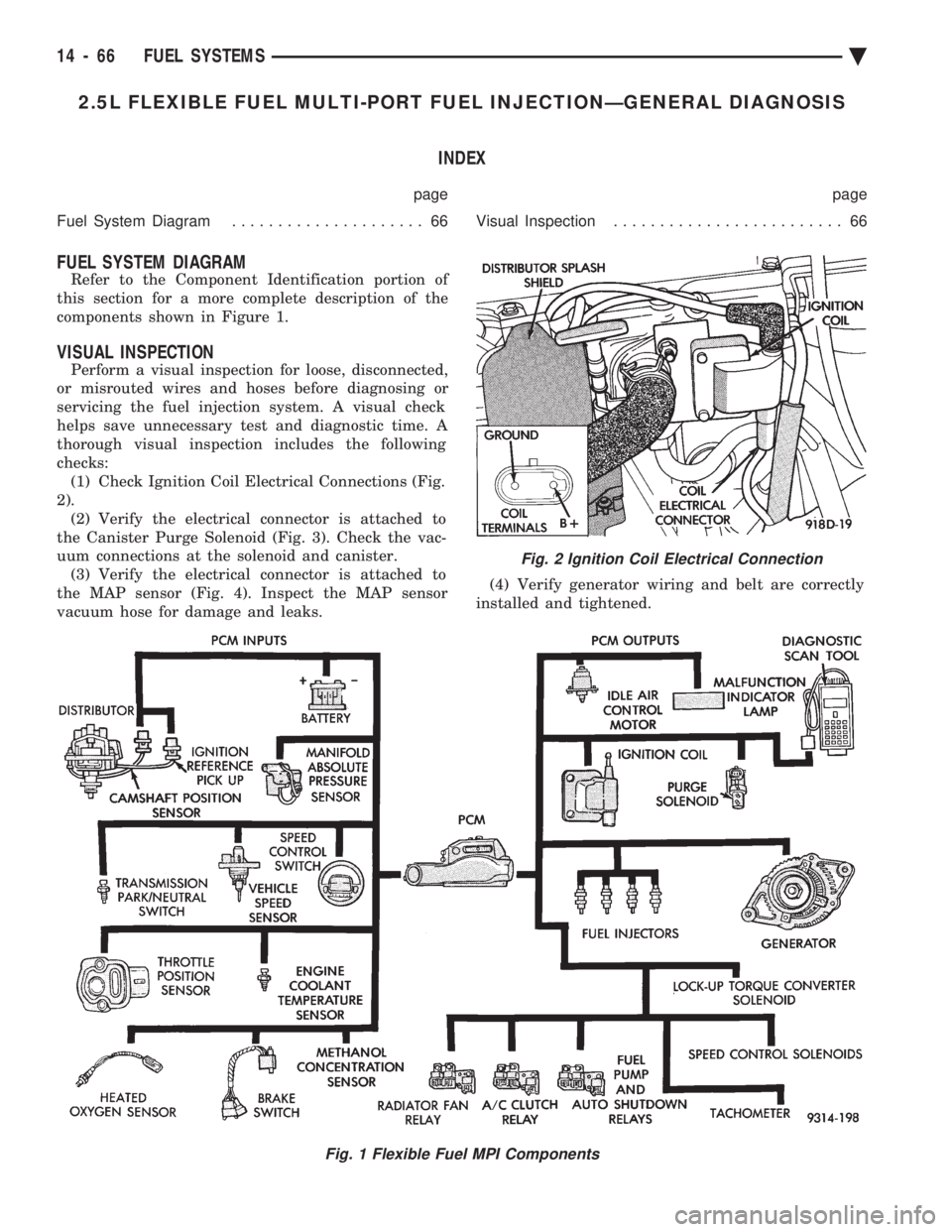
Refer to the Component Identification portion of
this section for a more complete description of the
components shown in Figure 1.
VISUAL INSPECTION
Perform a visual inspection for loose, disconnected,
or misrouted wires and hoses before diagnosing or
servicing the fuel injection system. A visual check
helps save unnecessary test and diagnostic time. A
thorough visual inspection includes the following
checks: (1) Check Ignition Coil Electrical Connections (Fig.
2). (2) Verify the electrical connector is attached to
the Canister Purge Solenoid (Fig. 3). Check the vac-
uum connections at the solenoid and canister. (3) Verify the electrical connector is attached to
the MAP sensor (Fig. 4). Inspect the MAP sensor
vacuum hose for damage and leaks. (4) Verify generator wiring and belt are correctly
installed and tightened.
Fig. 1 Flexible Fuel MPI Components
Fig. 2 Ignition Coil Electrical Connection
14 - 66 FUEL SYSTEMS Ä
Page 1845 of 2438
Wastegate Duty Cycle
Battery Temperature
Map Sensor Voltage
Vehicle Speed
Oxygen Sensor State
Baro Read Update
MAP Gauge Reading
Throttle Opening (percentage)
Total Spark Advance
CIRCUIT ACTUATION TEST MODE
The purpose of the circuit actuation test mode is to
check for the proper operation of output circuits or
devices which the powertrain control module (PCM)
cannot internally recognize. The PCM can attempt to
activate these outputs and allow an observer to ver-
ify proper operation. Most of the tests available in
this mode provide an audible or visual indication of
device operation (click of relay contacts, spray fuel,
etc.). With the exception of an intermittent condition,
if a device functions properly during its test, assume
the device, its associated wiring, and its driver cir-
cuit are in working order.
OBTAINING CIRCUIT ACTUATION TEST
Connect the DRBII scan tool to the vehicle and ac-
cess the Actuators screen. The following is a list of
the engine control system functions accessible
through Actuators screens. Stop All Tests
Ignition Coil #1
Ignition Coil #2
Fuel Injector #1
Fuel Injector #2
Fuel Injector #3
Idle Air Control Motor Open/Close
Radiator Fan Relay
A/C Clutch Relay
Auto Shutdown Relay
Purge Solenoid
S/C Serv Solenoids
Generator Field
Tachometer Output
Wastegate Solenoid
Baro Read Solenoid
All Solenoids/Relays
Speed Control Vent Solenoid
Speed Control Vacuum Solenoid
ASD Fuel System Test
Fuel Injector #4
THROTTLE BODY MINIMUM AIR FLOW CHECK
PROCEDURE
(1) Warm the engine in neutral until the cooling
fan has cycled on and off at least once. (2) Shut off engine.
(3) Hook-up Tachometer.
(4) Disconnect the PCV valve hose from the nipple
on the intake manifold. (5) Attach air metering fitting, special tool 6457
(0.125 inch orifice), to the intake manifold PCV nip-
ple. (6) Disconnect 3/16 inch manifold vacuum purge
line from the top of the throttle body. Cap the 3/16
inch throttle body nipple. (7) Connect DRBII scan tool.
(8) Restart engine. Allow engine to idle for at least
one minute. (9) Using the DRBII scan tool, access Min. Airflow
Idle Spd. The following will then occur:
² Idle air control motor will fully close.
² Idle spark advance will become fixed.
² Engine RPM will be displayed on the DRBII scan
tool. (10) Check idle RPM with tachometer, if idle RPM
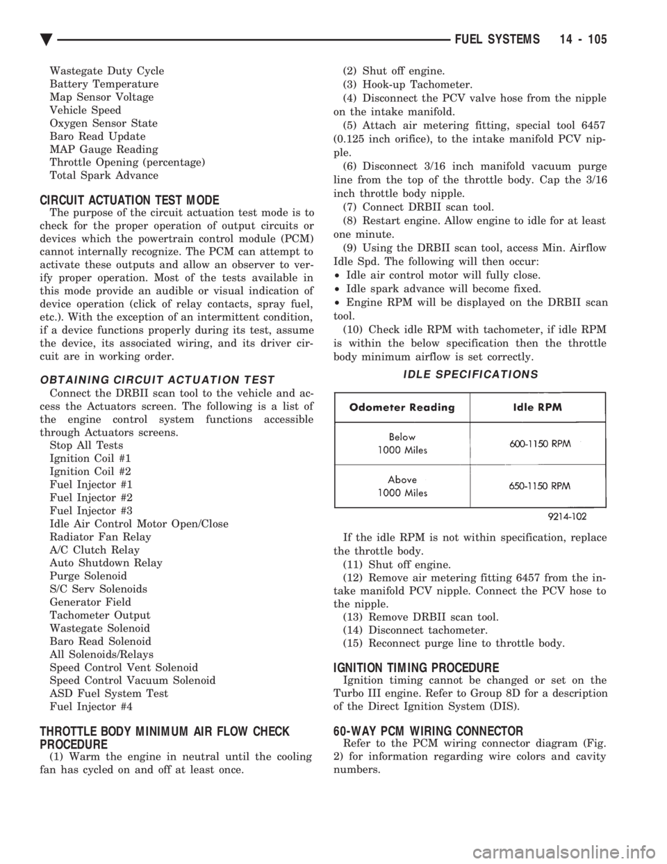
is within the below specification then the throttle
body minimum airflow is set correctly.
If the idle RPM is not within specification, replace
the throttle body. (11) Shut off engine.
(12) Remove air metering fitting 6457 from the in-
take manifold PCV nipple. Connect the PCV hose to
the nipple. (13) Remove DRBII scan tool.
(14) Disconnect tachometer.
(15) Reconnect purge line to throttle body.
IGNITION TIMING PROCEDURE
Ignition timing cannot be changed or set on the
Turbo III engine. Refer to Group 8D for a description
of the Direct Ignition System (DIS).
60-WAY PCM WIRING CONNECTOR
Refer to the PCM wiring connector diagram (Fig.
2) for information regarding wire colors and cavity
numbers.
IDLE SPECIFICATIONS
Ä FUEL SYSTEMS 14 - 105
Page 1878 of 2438
3.0L MULTI-PORT FUEL INJECTIONÐSERVICE PROCEDURES INDEX
page page
Idle Air Control Motor .................... 138
Canister Purge Solenoid Service ............ 143
Fuel Injector Rail Assembly ................ 139
Fuel Injectors .......................... 142
Fuel Pressure Regulator Service ............ 141
Fuel System Pressure Release Procedure ..... 138 Heated Oxygen Sensor (O
2Sensor)
......... 144
Manifold Absolute Pressure (MAP) Sensor ..... 143
PCM ................................. 143
Throttle Body ........................... 138
Throttle Body Service .................... 138
Throttle Position Sensor .................. 138
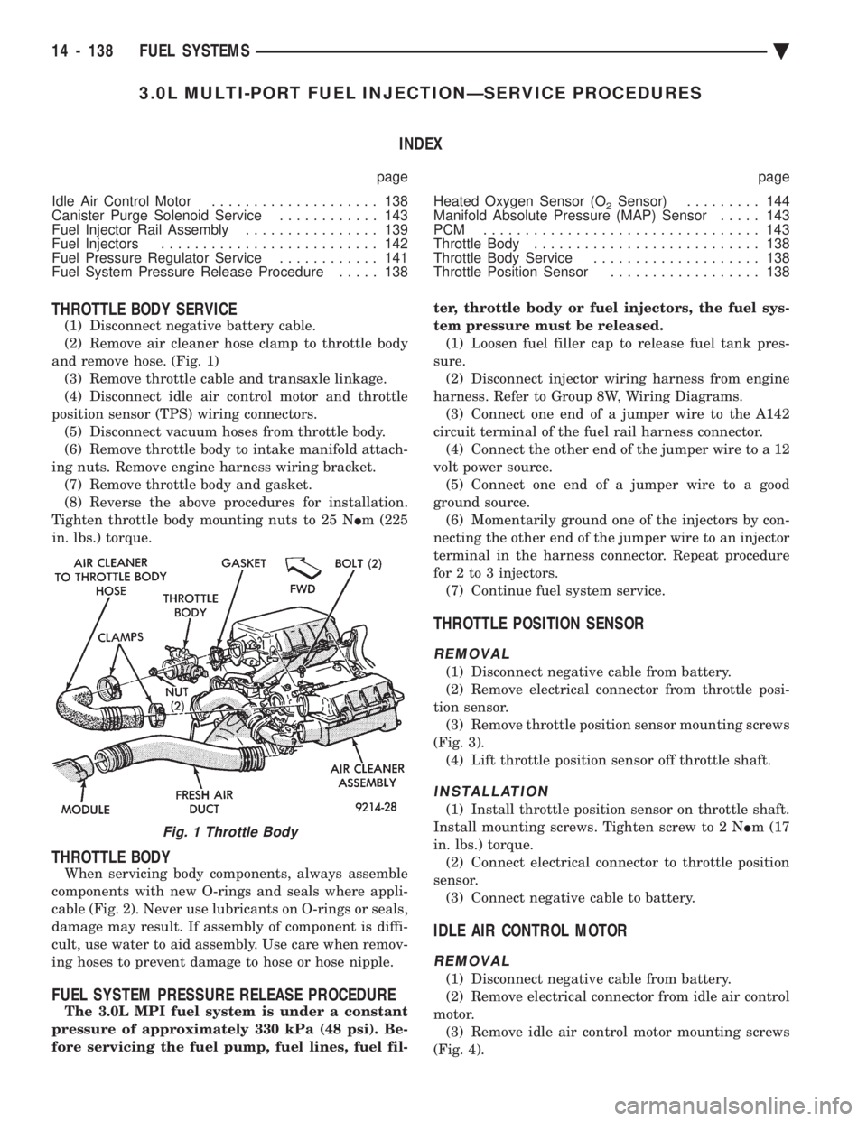
THROTTLE BODY SERVICE
(1) Disconnect negative battery cable.
(2) Remove air cleaner hose clamp to throttle body
and remove hose. (Fig. 1) (3) Remove throttle cable and transaxle linkage.
(4) Disconnect idle air control motor and throttle
position sensor (TPS) wiring connectors. (5) Disconnect vacuum hoses from throttle body.
(6) Remove throttle body to intake manifold attach-
ing nuts. Remove engine harness wiring bracket. (7) Remove throttle body and gasket.
(8) Reverse the above procedures for installation.
Tighten throttle body mounting nuts to 25 N Im (225
in. lbs.) torque.
THROTTLE BODY
When servicing body components, always assemble
components with new O-rings and seals where appli-
cable (Fig. 2). Never use lubricants on O-rings or seals,
damage may result. If assembly of component is diffi-
cult, use water to aid assembly. Use care when remov-
ing hoses to prevent damage to hose or hose nipple.
FUEL SYSTEM PRESSURE RELEASE PROCEDURE
The 3.0L MPI fuel system is under a constant
pressure of approximately 330 kPa (48 psi). Be-
fore servicing the fuel pump, fuel lines, fuel fil- ter, throttle body or fuel injectors, the fuel sys-
tem pressure must be released. (1) Loosen fuel filler cap to release fuel tank pres-
sure. (2) Disconnect injector wiring harness from engine
harness. Refer to Group 8W, Wiring Diagrams. (3) Connect one end of a jumper wire to the A142
circuit terminal of the fuel rail harness connector. (4) Connect the other end of the jumper wire to a 12
volt power source. (5) Connect one end of a jumper wire to a good
ground source. (6) Momentarily ground one of the injectors by con-
necting the other end of the jumper wire to an injector
terminal in the harness connector. Repeat procedure
for 2 to 3 injectors. (7) Continue fuel system service.
THROTTLE POSITION SENSOR
REMOVAL
(1) Disconnect negative cable from battery.
(2) Remove electrical connector from throttle posi-
tion sensor. (3) Remove throttle position sensor mounting screws
(Fig. 3). (4) Lift throttle position sensor off throttle shaft.
INSTALLATION
(1) Install throttle position sensor on throttle shaft.
Install mounting screws. Tighten screw to 2 N Im (17
in. lbs.) torque. (2) Connect electrical connector to throttle position
sensor. (3) Connect negative cable to battery.
IDLE AIR CONTROL MOTOR
REMOVAL
(1) Disconnect negative cable from battery.
(2) Remove electrical connector from idle air control
motor. (3) Remove idle air control motor mounting screws
(Fig. 4).
Fig. 1 Throttle Body
14 - 138 FUEL SYSTEMS Ä
Page 1907 of 2438
(10) The following will then occur:
² Idle air control motor will fully close.
² Idle spark advance will become fixed.
² Engine RPM will be displayed on DRBII scan tool.
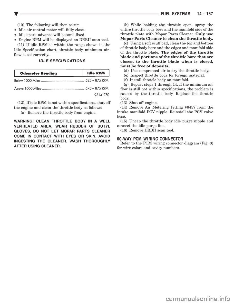
(11) If idle RPM is within the range shown in the
Idle Specification chart, throttle body minimum air-
flow is set correctly.
(12) If idle RPM is not within specifications, shut off
the engine and clean the throttle body as follows: (a) Remove the throttle body from engine.
WARNING: CLEAN THROTTLE BODY IN A WELL
VENTILATED AREA. WEAR RUBBER OF BUTYL
GLOVES, DO NOT LET MOPAR PARTS CLEANER
COME IN CONTACT WITH EYES OR SKIN. AVOID
INGESTING THE CLEANER. WASH THOROUGHLY
AFTER USING CLEANER. (b) While holding the throttle open, spray the
entire throttle body bore and the manifold side of the
throttle plate with Mopar Parts Cleaner. Only use
Mopar Parts Cleaner to clean the throttle body. (c) Using a soft scuff pad, clean the top and bottom
of throttle body bore and the edges and manifold side
of the throttle blade. The edges of the throttle
blade and portions of the throttle bore that are
closest to the throttle blade when is closed,
must be free of deposits. (d) Use compressed air to dry the throttle body.
(e) Inspect throttle body for foreign material.
(f) Install throttle body on manifold.
(g) Repeat steps 1 through 14. If the minimum air
flow is still not within specifications, the problem is
caused by the throttle body. Replace the throttle
body.
(13) Shut off engine.
(14) Remove Air Metering Fitting #6457 from the
intake manifold PCV nipple. Reinstall the PCV valve
hose. (15) Uncap the throttle body idle purge nipple and
connect the idle purge line. (16) Remove DRBII scan tool.
60-WAY PCM WIRING CONNECTOR
Refer to the PCM wiring connector diagram (Fig. 3)
for wire colors and cavity numbers.
IDLE SPECIFICATIONS
Ä FUEL SYSTEMS 14 - 167