1993 CHEVROLET PLYMOUTH ACCLAIM automatic transmission
[x] Cancel search: automatic transmissionPage 31 of 2438
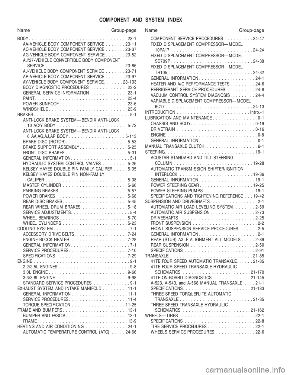
COMPONENT AND SYSTEM INDEX
Name Group-page Name Group-page
BODY ................................... 23-1
AA-VEHICLE BODY COMPONENT SERVICE .......23-11
AC-VEHICLE BODY COMPONENT SERVICE .......23-37
AG-VEHICLE BODY COMPONENT SERVICE .......23-52
AJ/27-VEHICLE CONVERTIBLE BODY COMPONENT SERVICE ............................ 23-86
AJ-VEHICLE BODY COMPONENT SERVICE .......23-71
AP-VEHICLE BODY COMPONENT SERVICE .......23-97
AY-VEHICLE BODY COMPONENT SERVICE .......23-133
BODY DIAGNOSTIC PROCEDURES .............23-2
GENERAL SERVICE INFORMATION .............23-1
PAINT ................................. 23-4
POWER SUNROOF ........................ 23-6
WINDSHIELD ............................ 23-9
BRAKES ..................................5-1
ANTI-LOCK BRAKE SYSTEMÐBENDIX ANTI-LOCK 10 AC/Y BODY ......................... 5-72
ANTI-LOCK BRAKE SYSTEMÐBENDIX ANTI-LOCK 6 AA,AG,AJ,AP BODY .................... 5-113
BRAKE DISC (ROTOR) ...................... 5-53
BRAKE SUPPORT ASSEMBLY .................5-25
FRONT DISC BRAKES ...................... 5-31
GENERAL INFORMATION .....................5-1
HYDRAULIC SYSTEM CONTROL VALVES .........5-26
KELSEY HAYES DOUBLE PIN FAMILY CALIPER .....5-35
KELSEY HAYES DOUBLE PIN NON-FAMILY CALIPER ............................. 5-38
MASTER CYLINDER ....................... 5-66
PARKING BRAKES ........................ 5-57
POWER BRAKES ......................... 5-68
REAR DISC BRAKES ....................... 5-45
REAR WHEEL DRUM BRAKES ................5-18
SERVICE ADJUSTMENTS .....................5-4
WHEEL BEARINGS ........................ 5-70
WHEEL CYLINDERS ....................... 5-23
COOLING SYSTEM ...........................7-1
ACCESSORY DRIVE BELTS ................... 7-24
ENGINE BLOCK HEATER .................... 7-28
GENERAL INFORMATION .....................7-1
SERVICE PROCEDURES ..................... 7-10
SPECIFICATIONS ......................... 7-29
ENGINE ..................................9-1
2.2/2.5L ENGINES .........................9-8
3.0L ENGINE ............................ 9-66
3.3/3.8L ENGINE ......................... 9-98
STANDARD SERVICE PROCEDURES .............9-1
EXHAUST SYSTEM AND INTAKE MANIFOLD .........11-1
GENERAL INFORMATION .................... 11-1
SERVICE PROCEDURES ..................... 11-4
TORQUE SPECIFICATION ................... 11-25
FRAME AND BUMPERS ....................... 13-1
BUMPER AND FASCIA ...................... 13-1
FRAME ................................ 13-9
HEATING AND AIR CONDITIONING ...............24-1
AUTOMATIC TEMPERATURE CONTROL (ATC) .....24-66 COMPONENT SERVICE PROCEDURES
..........24-47
FIXED DISPLACEMENT COMPRESSORÐMODEL 10PA17............................. 24-24
FIXED DISPLACEMENT COMPRESSORÐMODEL SD709P ............................. 24-38
FIXED DISPLACEMENT COMPRESSORÐMODEL TR105 .............................. 24-32
GENERAL INFORMATION .................... 24-1
HEATER AND A/C PERFORMANCE TESTS .........24-6
REFRIGERANT SERVICE PROCEDURES ..........24-8
VACUUM CONTROL SYSTEM DIAGNOSIS .........24-4
VARIABLE DISPLACEMENT COMPRESSORÐMODEL 6C17 ............................... 24-13
INTRODUCTION .......................... Intro.-1
LUBRICATION AND MAINTENANCE ................0-1
CHASSIS AND BODY ....................... 0-19
DRIVETRAIN ............................ 0-16
ENGINE ................................0-8
GENERAL INFORMATION .....................0-1
MANUAL TRANSAXLE CLUTCH ...................6-1
STEERING ................................ 19-1
ACUSTAR STANDARD AND TILT STEERING COLUMN ............................ 19-28
AUTOMATIC TRANSMISSION SHIFTER/IGNITION INTERLOCK .......................... 19-36
GENERAL INFORMATION .................... 19-1
POWER STEERING GEAR ................... 19-25
POWER STEERING PUMPS ..................19-1
SPECIFICATIONS AND TIGHTENING REFERENCE . . . 19-42
SUSPENSION AND DRIVESHAFTS .................2-1
AUTOMATIC AIR LOAD LEVELING SYSTEM ........2-59
AUTOMATIC AIR SUSPENSION ................2-73
DRIVESHAFTS ........................... 2-25
FRONT SUSPENSION .......................2-2
FRONT SUSPENSION SERVICE PROCEDURES .......2-5
GENERAL INFORMATION .....................2-1
REAR (STUB) AXLE ALIGNMENT ALL MODELS .....2-89
REAR SUSPENSION ....................... 2-50
SPECIFICATIONS ......................... 2-91
TRANSAXLE .............................. 21-85
41TE FOUR SPEED AUTOMATIC TRANSAXLE ......21-85
41TE FOUR SPEED TRANSAXLE HYDRAULIC SCHEMATICS ........................ 21-170
41TE ON-BOARD DIAGNOSTICS .............21-145
A-523, A-543, and A-568 MANUAL TRANSAXLE ....21-1
SPECIFICATIONS ........................ 21-183
THREE SPEED TORQUEFLITE AUTOMATIC TRANSAXLE .......................... 21-35
THREE SPEED TRANSAXLE HYDRAULIC SCHEMATICS ........................ 21-162
WHEELSÐTIRES ........................... 22-1
SPECIFICATIONS ......................... 22-8
TIRE SERVICE PROCEDURES .................22-1
WHEELS SERVICE PROCEDURES ..............22-6
Page 53 of 2438
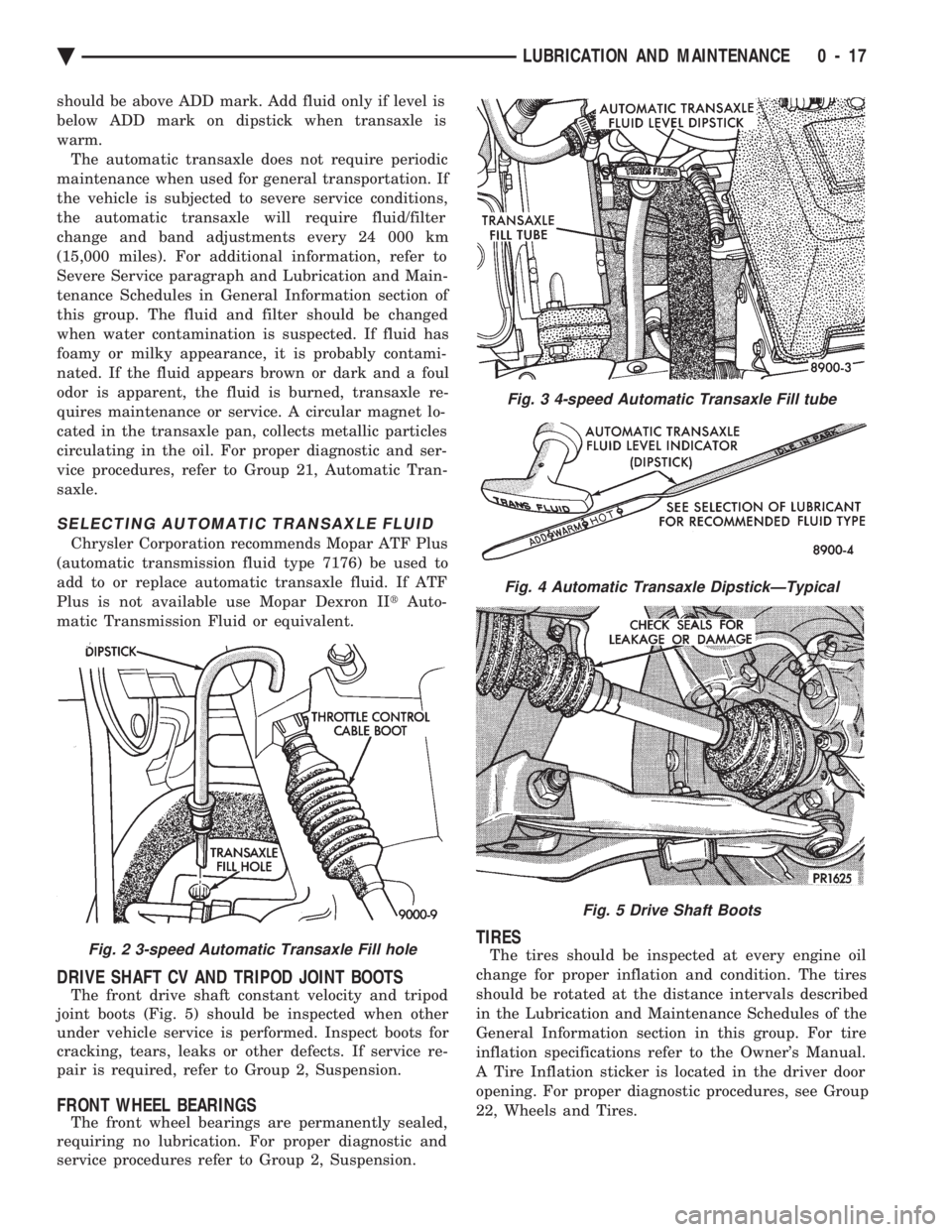
should be above ADD mark. Add fluid only if level is
below ADD mark on dipstick when transaxle is
warm.The automatic transaxle does not require periodic
maintenance when used for general transportation. If
the vehicle is subjected to severe service conditions,
the automatic transaxle will require fluid/filter
change and band adjustments every 24 000 km
(15,000 miles). For additional information, refer to
Severe Service paragraph and Lubrication and Main-
tenance Schedules in General Information section of
this group. The fluid and filter should be changed
when water contamination is suspected. If fluid has
foamy or milky appearance, it is probably contami-
nated. If the fluid appears brown or dark and a foul
odor is apparent, the fluid is burned, transaxle re-
quires maintenance or service. A circular magnet lo-
cated in the transaxle pan, collects metallic particles
circulating in the oil. For proper diagnostic and ser-
vice procedures, refer to Group 21, Automatic Tran-
saxle.
SELECTING AUTOMATIC TRANSAXLE FLUID
Chrysler Corporation recommends Mopar ATF Plus
(automatic transmission fluid type 7176) be used to
add to or replace automatic transaxle fluid. If ATF
Plus is not available use Mopar Dexron II tAuto-
matic Transmission Fluid or equivalent.
DRIVE SHAFT CV AND TRIPOD JOINT BOOTS
The front drive shaft constant velocity and tripod
joint boots (Fig. 5) should be inspected when other
under vehicle service is performed. Inspect boots for
cracking, tears, leaks or other defects. If service re-
pair is required, refer to Group 2, Suspension.
FRONT WHEEL BEARINGS
The front wheel bearings are permanently sealed,
requiring no lubrication. For proper diagnostic and
service procedures refer to Group 2, Suspension.
TIRES
The tires should be inspected at every engine oil
change for proper inflation and condition. The tires
should be rotated at the distance intervals described
in the Lubrication and Maintenance Schedules of the
General Information section in this group. For tire
inflation specifications refer to the Owner's Manual.
A Tire Inflation sticker is located in the driver door
opening. For proper diagnostic procedures, see Group
22, Wheels and Tires.Fig. 2 3-speed Automatic Transaxle Fill hole
Fig. 3 4-speed Automatic Transaxle Fill tube
Fig. 4 Automatic Transaxle DipstickÐTypical
Fig. 5 Drive Shaft Boots
Ä LUBRICATION AND MAINTENANCE 0 - 17
Page 352 of 2438
SERVICE PROCEDURES INDEX
page page
Automatic Transmission Oil Coolers .......... 23
Coolant ................................ 14
Coolant Recovery System (CRS) ............. 17
Cooling System Drain, Clean, Flush and Refill . . 15
Electric Fan Motor ........................ 22
Engine Thermostats ....................... 13
Fan Shroud ............................. 23 Fans
.................................. 21
Radiator Hoses .......................... 21
Radiator Pressure Cap .................... 18
Radiators ............................... 18
Testing System for Leaks .................. 17
Water Pumps ........................... 10
WATER PUMPS
A quick test to tell whether or not the pump is
working is to see if the heater warms properly. A
defective pump will not be able to circulate heated
coolant through the long heater hose. The water pump on all models can be replaced
without discharging the air conditioning system.
WATER PUMPÐ2.2/2.5L ENGINE
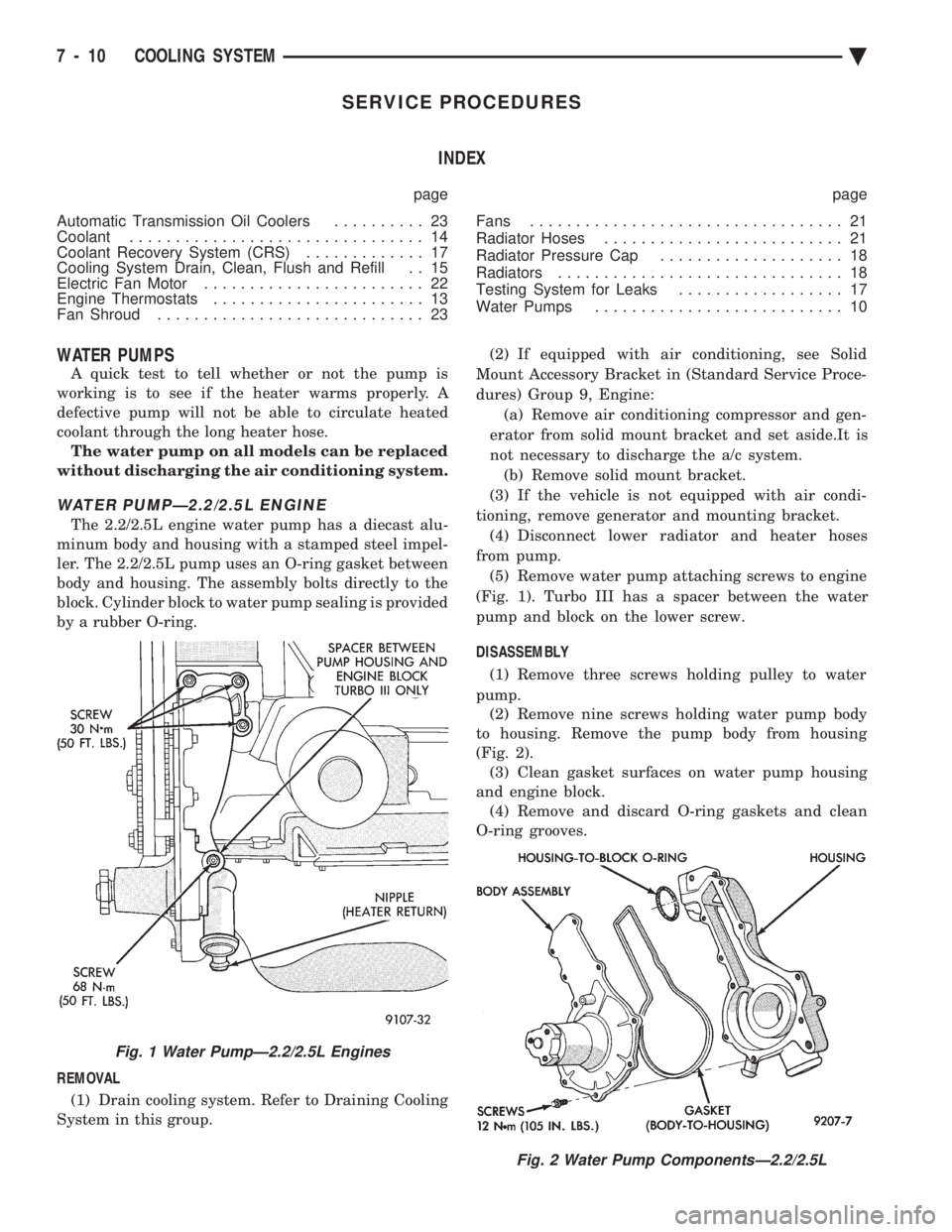
The 2.2/2.5L engine water pump has a diecast alu-
minum body and housing with a stamped steel impel-
ler. The 2.2/2.5L pump uses an O-ring gasket between
body and housing. The assembly bolts directly to the
block. Cylinder block to water pump sealing is provided
by a rubber O-ring.
REMOVAL (1) Drain cooling system. Refer to Draining Cooling
System in this group. (2) If equipped with air conditioning, see Solid
Mount Accessory Bracket in (Standard Service Proce-
dures) Group 9, Engine: (a) Remove air conditioning compressor and gen-
erator from solid mount bracket and set aside.It is
not necessary to discharge the a/c system. (b) Remove solid mount bracket.
(3) If the vehicle is not equipped with air condi-
tioning, remove generator and mounting bracket. (4) Disconnect lower radiator and heater hoses
from pump. (5) Remove water pump attaching screws to engine
(Fig. 1). Turbo III has a spacer between the water
pump and block on the lower screw.
DISASSEMBLY (1) Remove three screws holding pulley to water
pump. (2) Remove nine screws holding water pump body
to housing. Remove the pump body from housing
(Fig. 2). (3) Clean gasket surfaces on water pump housing
and engine block. (4) Remove and discard O-ring gaskets and clean
O-ring grooves.
Fig. 2 Water Pump ComponentsÐ2.2/2.5L
Fig. 1 Water PumpÐ2.2/2.5L Engines
7 - 10 COOLING SYSTEM Ä
Page 362 of 2438

(2) Remove radiator pressure cap when engine is
cold, Idle engine until thermostat opens, you should
observe coolant flow while looking down the filler
neck. Once flow is detected install radiator pressure
cap.
RADIATOR
REMOVAL
(1) Disconnect negative battery cable from battery.
WARNING: DO NOT REMOVE THE CYLINDER
BLOCK PLUG OR THE RADIATOR DRAINCOCK
WITH THE SYSTEM HOT AND UNDER PRESSURE
BECAUSE SERIOUS BURNS FROM COOLANT CAN
OCCUR.
(2) Drain cooling system. Refer to Draining Cool-
ing System of this section. (3) Remove hose clamps and hoses from the radia-
tor (Fig. 11). Remove coolant reserve system tank to
filler neck tube. (4) Remove automatic transmission hoses, if
equipped. (5) Remove fan and fan support assembly by dis-
connecting fan motor electrical connector. Remove
fan shroud retaining clips, located on the top and
bottom of the shroud for AA, AG, AJ and AP vehi-
cles. AC/AY vehicle retainer clips are located on the
top only. Lift shroud up and out of bottom shroud at-
tachment clips separating shroud from radiator. Fan
damage should always be avoided. (6) Remove upper radiator mounting screws. Dis-
connect the engine block heater wire if equipped. (7) Remove the air conditioning condenser attaching
screws located at the top front of the radiator,if
equipped. Radiator can now be lifted free from engine compart-
ment. Care should be taken not to damage radia-
tor cooling fins or water tubes during removal.
INSTALLATION
(1) Slide radiator down into position behind radiator
support (yoke). (2) Attach air conditioning condenser to radiator, if
equipped, with a force of approximately 10 lbs. to seat
the radiator assembly lower rubber isolators in the
mount holes provided. (3) Tighten radiator mounting screws to 11.9N Im
(105 in. lbs.). (4) Connect automatic transmission hoses, if
equipped. Tighten hose clamps to 4 N Im (35 in. lbs.).
(5) Slide fan shroud, fan and motor down into clips
on lower radiator flange. Replace shroud retaining
clips. (6) Install upper and lower radiator hoses (including
coolant reserve hose). (7) Connect fan motor electrical connection and con-
nect negative battery cable. (8) Fill cooling system with coolant. Refer to Refill-
ing Cooling Systems. in this group.
(9) Operate engine until it reaches normal operating
temperature. Check cooling system and automatic
transmission for correct fluid levels.
Fig. 11 Cooling ModulesÐAll Models
7 - 20 COOLING SYSTEM Ä
Page 365 of 2438
FAN SHROUD
All vehicles have fan shrouds to improve fan air
flow efficiency. These fan shrouds cover less than full
radiator frontal area to prevent the shroud from re-
stricting air flow at high speeds. The shroud supports the electric fan motor and fan.
For removal and installation see Radiator Section.
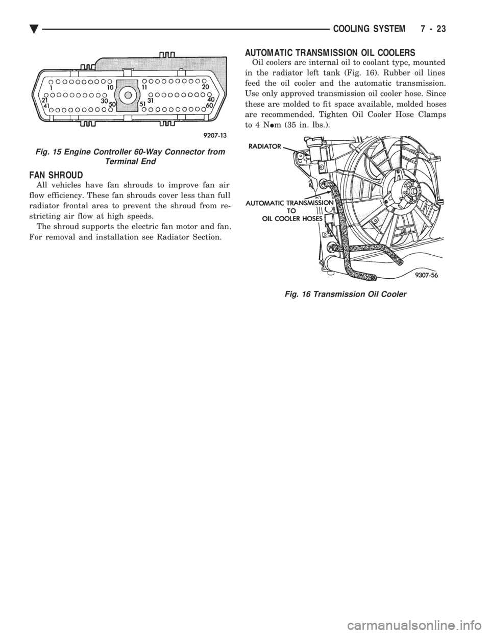
AUTOMATIC TRANSMISSION OIL COOLERS
Oil coolers are internal oil to coolant type, mounted
in the radiator left tank (Fig. 16). Rubber oil lines
feed the oil cooler and the automatic transmission.
Use only approved transmission oil cooler hose. Since
these are molded to fit space available, molded hoses
are recommended. Tighten Oil Cooler Hose Clamps
to4N Im (35 in. lbs.).
Fig. 15 Engine Controller 60-Way Connector from
Terminal End
Fig. 16 Transmission Oil Cooler
Ä COOLING SYSTEM 7 - 23
Page 381 of 2438

IGNITION OFF DRAW (IOD)
GENERAL INFORMATION
A normal electrical system will draw from 5 to 30
milliamperes from the battery. This is with the ignition
in the OFF position, and all non-ignition controlled cir-
cuits in proper working order. The amount of IOD will
depend on body model and electrical components. A ve-
hicle that has not been operated for an extended period
of approximately 20 days may discharge the battery to
an inadequate level. In this case, the Main Fusible Link
Connector should be disconnected. The Main Fusible
Link connector is located rearward of the battery on the
engine wiring harness (Fig. 19).
If the IOD is over 30 milliamperes, the defect must
be found and corrected before condemning the bat-
tery. Usually, the battery can be charged and re-
turned to service (Fig. 16).
IGNITION OFF DRAW (IOD) TESTS
VEHICLES WITHOUT ELECTRONIC AUTOMATIC TRANSMISSION/LOAD LEVELINGSUSPENSION OR ALARM SYSTEMS
Testing for HIGHER AMPERAGE IOD must be
performed first to prevent damage to most milliamp
meters. A standard 12 volt test light and a milliamp meter
that is equipped with two leads will be used for the
following tests. The milliamp meter should be able to
handle up to two amps.
(1) Verify that all electrical accessories are OFF.
Turn off all lights, close trunk lid, close glove box door,
turn off sun visor vanity lights, close all doors and re- move ignition key. Allow the Illuminated Entry System
if equipped to time out in approximately 30 seconds.
(2) Verify the engine compartment lamp bulb is
working by opening/closing hood. Remove the lamp. (3) Disconnect negative battery cable (Fig. 15).
(4) Connect a typical 12 volt test light between the
negative cable clamp and the negative battery post (Fig.
19). The test light may be brightly lit for up to three
minutes or may not be lit at all. This depending on the
body model or electronic components on the vehicle. (a) The term brightly used throughout the follow-
ing tests. This implies the brightness of the test light
will be the same as if it were connected across the
battery posts. This would be with a fully charged bat-
tery.
(b) The test light or the milliamp meter MUST
be positively connected to the battery post and the
battery cable during all IOD testing. (c) Do not allow the test light or the milliamp
meter to become disconnected during any of the
IOD tests. If this happens, the electronic timer
functions will be started and all IOD tests must be
repeated from the beginning. Clamp the test light
at both ends to prevent accidental disconnection.
(d) After three minutes time has elapsed, the test
light should turn OFF or be dimly lit depending on
the electronic components on the vehicle. If the test
light remains BRIGHTLY lit, do not disconnect test
light. Disconnect each fuse or circuit breaker until
test light is either OFF or DIMLY lit. Refer to the
Front Wheel Drive Car Wiring Diagrams Service
Manual. This will eliminate higher amperage IOD. It
is now safe to install the milliamp meter without
damage to the meter to check for low amperage IOD.
(e) Possible sources of high IOD are usually ve-
hicle lamps trunk lamp, glove compartment, lug-
gage compartment, etc.. (f) If test light is still brightly lit after discon-
necting each fuse and circuit breaker, disconnect
the wiring harness from the generator. Refer to
Generator Testing. Do not disconnect test light.
CAUTION: This last test has higher amperage IOD and
must be performed before going on with low amper-
age IOD tests. The higher amperage IOD must be elim-
inated before hooking up milliamp meter to check for
low amperage IOD. If higher amperage IOD has not
been eliminated, milliamp meter may be damaged.
Most milliamp meters will not handle over one or two
amps. Do not hook up meter if test light is glowing
brightly. Refer to maximum amperage specifications
and instructions supplied with milliamp meter.
After higher amperage IOD has been corrected, low
amperage IOD may be checked. The MAXIMUM IOD=
30 MILLIAMPERES.
Fig. 19 IOD Test
Ä BATTERY/STARTING/CHARGING SYSTEMS DIAGNOSTICS 8A - 9
Page 382 of 2438
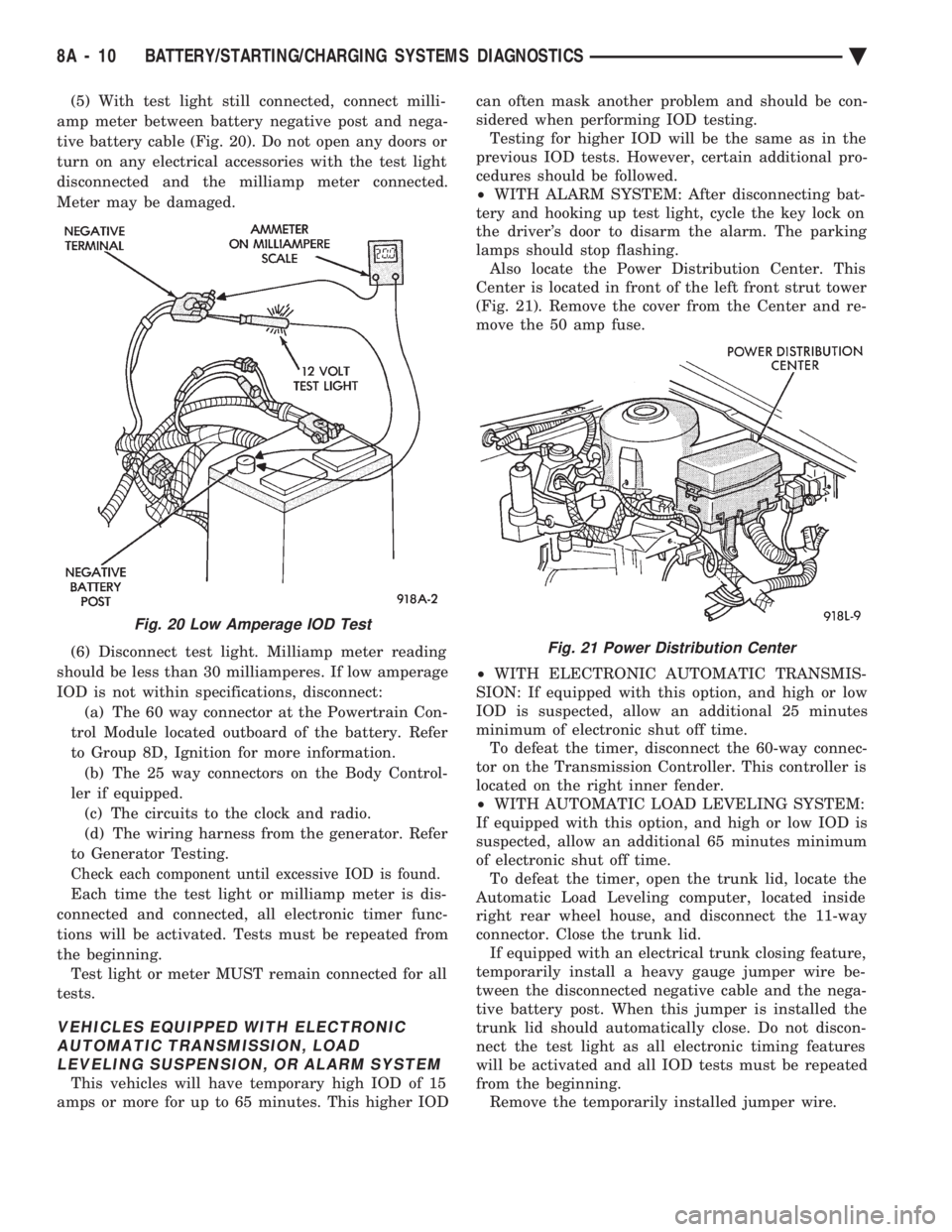
(5) With test light still connected, connect milli-
amp meter between battery negative post and nega-
tive battery cable (Fig. 20). Do not open any doors or
turn on any electrical accessories with the test light
disconnected and the milliamp meter connected.
Meter may be damaged.
(6) Disconnect test light. Milliamp meter reading
should be less than 30 milliamperes. If low amperage
IOD is not within specifications, disconnect: (a) The 60 way connector at the Powertrain Con-
trol Module located outboard of the battery. Refer
to Group 8D, Ignition for more information. (b) The 25 way connectors on the Body Control-
ler if equipped. (c) The circuits to the clock and radio.
(d) The wiring harness from the generator. Refer
to Generator Testing.
Check each component until excessive IOD is found.
Each time the test light or milliamp meter is dis-
connected and connected, all electronic timer func-
tions will be activated. Tests must be repeated from
the beginning. Test light or meter MUST remain connected for all
tests.
VEHICLES EQUIPPED WITH ELECTRONIC AUTOMATIC TRANSMISSION, LOADLEVELING SUSPENSION, OR ALARM SYSTEM
This vehicles will have temporary high IOD of 15
amps or more for up to 65 minutes. This higher IOD can often mask another problem and should be con-
sidered when performing IOD testing. Testing for higher IOD will be the same as in the
previous IOD tests. However, certain additional pro-
cedures should be followed.
² WITH ALARM SYSTEM: After disconnecting bat-
tery and hooking up test light, cycle the key lock on
the driver's door to disarm the alarm. The parking
lamps should stop flashing. Also locate the Power Distribution Center. This
Center is located in front of the left front strut tower
(Fig. 21). Remove the cover from the Center and re-
move the 50 amp fuse.
² WITH ELECTRONIC AUTOMATIC TRANSMIS-
SION: If equipped with this option, and high or low
IOD is suspected, allow an additional 25 minutes
minimum of electronic shut off time. To defeat the timer, disconnect the 60-way connec-
tor on the Transmission Controller. This controller is
located on the right inner fender.
² WITH AUTOMATIC LOAD LEVELING SYSTEM:
If equipped with this option, and high or low IOD is
suspected, allow an additional 65 minutes minimum
of electronic shut off time. To defeat the timer, open the trunk lid, locate the
Automatic Load Leveling computer, located inside
right rear wheel house, and disconnect the 11-way
connector. Close the trunk lid. If equipped with an electrical trunk closing feature,
temporarily install a heavy gauge jumper wire be-
tween the disconnected negative cable and the nega-
tive battery post. When this jumper is installed the
trunk lid should automatically close. Do not discon-
nect the test light as all electronic timing features
will be activated and all IOD tests must be repeated
from the beginning. Remove the temporarily installed jumper wire.
Fig. 20 Low Amperage IOD Test
Fig. 21 Power Distribution Center
8A - 10 BATTERY/STARTING/CHARGING SYSTEMS DIAGNOSTICS Ä
Page 388 of 2438
relay to starter solenoid for loose or corroded connec-
tions. Particularly at starter terminals.
² Repeat test. If engine still fails to crank properly,
trouble is within starter or starter mounted solenoid,
and it must be removed for repairs. Refer to Group
8B, Battery/Starter/Generator Service, Starter re-
placement.
STARTER RELAY TEST
WARNING: CHECK TO ENSURE THAT THE TRANS-
MISSION IS IN PARK OR NEUTRAL WITH THE
PARKING BRAKE APPLIED
(1) Verify battery condition. Battery must be in
good condition with a full charge before performing
any starter tests. Refer to Battery Tests. (2) Perform the preceding starter solenoid tests
BEFORE performing starter relay tests. Refer to
Starter Solenoid Test. (3) Locate and remove the starter relay. For
starter relay locations, refer to Starter Solenoid Test
(Fig. 13 or 14). (4) After the starter relay has been located and re-
moved, refer to Starter Relay Tests (Fig. 15).
NEUTRAL STARTING AND BACK-UP SWITCH
AUTOMATIC TRANSMISSION ONLY
For electrical diagnostics, when checking starter
circuits, refer to Starter Relay Tests (Fig. 15). For replacement of switch, refer to Group 21, Tran-
saxle, Neutral Starting and Switch Replacement.
STARTER INTERLOCK SWITCHÐCLUTCH PEDAL MOUNTED
MANUAL TRANSMISSION ONLY
For electrical diagnostics, refer to the Starter Relay
Tests. For replacement and/or adjustment of the switch,
refer to Group 6, Manual Transaxle Clutch, Manual
Transaxle Starter Interlock Switch.
IGNITION SWITCH TEST
After testing the starter solenoid and relay, test ig-
nition switch and wiring. Refer to Group 8D, Ignition
Systems, or the Front Wheel Drive Car Wiring Dia-
grams Service Manual. Check all wiring for opens or
shorts, and all connectors for being loose or corroded.
BENCH TESTING STARTER SOLENOID
(1) Disconnect field coil wire from field coil termi-
nal (Fig. 16 or 17). (2) Check for continuity between solenoid terminal
and field coil terminal with a continuity tester. Con-
tinuity should be detected (Fig. 18 or 19). (3) Check for continuity between solenoid terminal
and solenoid housing (Fig. 20 or 21). Continuity
should be detected. If continuity is detected, solenoid
is good. (4) If continuity is not detected in either test, sole-
noid has an open circuit and is defective. If equipped
with:
² BOSCH STARTER: Replace the solenoid.
² NIPPONDENSO STARTER: Replace the starter
assembly.
8A - 16 BATTERY/STARTING/CHARGING SYSTEMS DIAGNOSTICS Ä