1993 CHEVROLET DYNASTY radiator
[x] Cancel search: radiatorPage 1723 of 2438

FRAME AND BUMPERS
CONTENTS
page page
BUMPER AND FASCIA .................... 1 FRAME................................ 9
BUMPER AND FASCIA INDEX
page page
AA-Vehicle Front Bumper ................... 1
AA-Vehicle Rear Bumper ................... 5
AC-Vehicle Front Bumper ................... 2
AC-Vehicle Rear Bumper ................... 6
AG-Vehicle Front Bumper ................... 3
AG-Vehicle Rear Bumper ................... 7
AJ-Vehicle Front Bumper and Fascia .......... 4 AJ-Vehicle Rear Bumper
.................... 7
AP-Vehicle Front Bumper ................... 4
AP-Vehicle Rear Bumper ................... 7
AY-Vehicle Front Bumper ................... 5
AY-Vehicle Rear Bumper ................... 8
Safety Precautions and Warnings ............. 1
SAFETY PRECAUTIONS AND WARNINGS
WARNING: BUMPER ENERGY ABSORBER UNITS
CONTAIN PRESSURIZE GAS. DO NOT PUNCTURE
OR HEAT ABSORBER UNIT FOR ANY REASON.
PERSONAL INJURY CAN RESULT.
DO NOT VENTURE UNDER A HOISTED VEHICLE
THAT IS NOT SUPPORTED ON SAFETY STANDS.
PERSONAL INJURY CAN RESULT.
CAUTION: To avoid damaging a bright metal or
painted finish bumper or fascia, use a padded work
surface.
AA-VEHICLE FRONT BUMPER
REMOVAL (FIG. 1)
(1) Remove socket and bulb from park and turn
lamp. (2) Disconnect horn and fog lamp connectors (if
equipped). (3) Remove push-in fasteners holding sight shield
to vertical support in front of radiator. (4) Remove nuts holding fascia to fender, from be-
hind forward flange of fender. (5) Support front bumper assembly on suitable lift-
ing device and remove bolts holding bumper rein-
forcement to energy absorber units.
INSTALLATION
Reverse the preceding operation. Align bumper
height to approximately 3 mm (1/8 in.) gap to bottom
of head lamp assemblies and flush to front fenders
below the side marker lamps.
Fig. 1 Standard Front BumperÐAA-Vehicle
Ä FRAME AND BUMPERS 13 - 1
Page 1724 of 2438
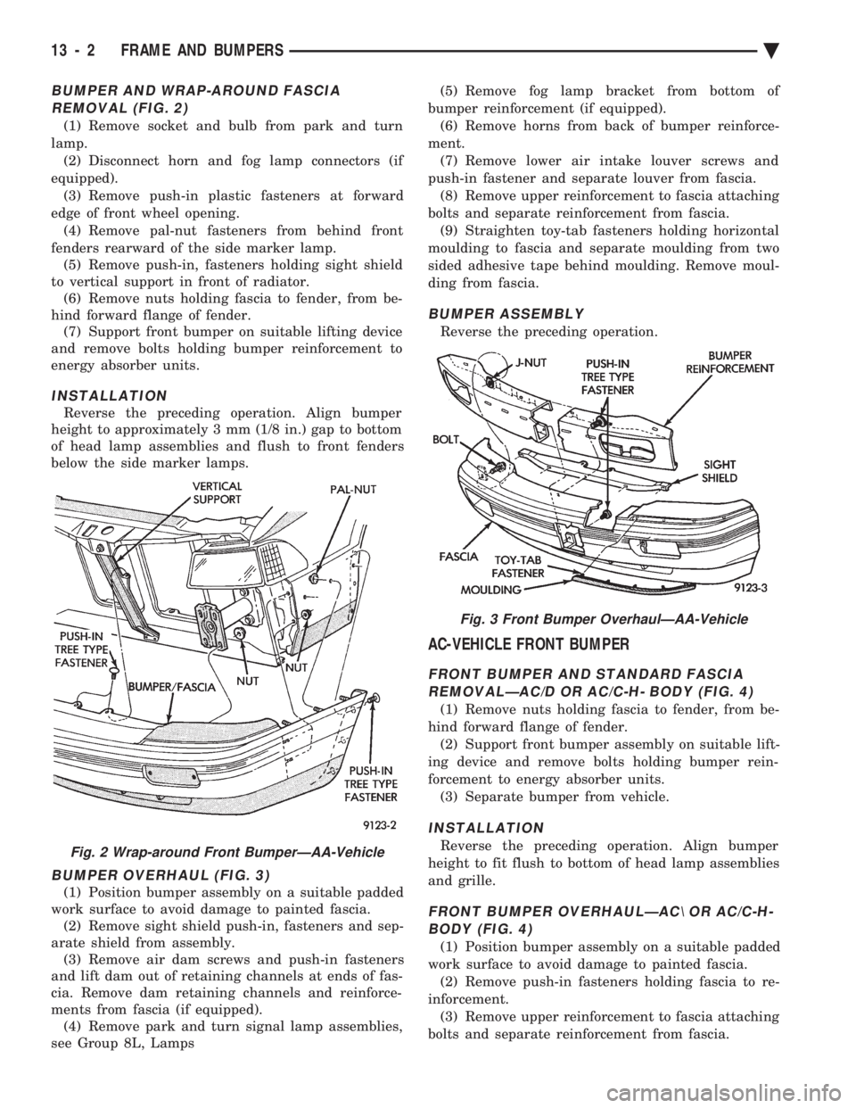
BUMPER AND WRAP-AROUND FASCIA REMOVAL (FIG. 2)
(1) Remove socket and bulb from park and turn
lamp. (2) Disconnect horn and fog lamp connectors (if
equipped). (3) Remove push-in plastic fasteners at forward
edge of front wheel opening. (4) Remove pal-nut fasteners from behind front
fenders rearward of the side marker lamp. (5) Remove push-in, fasteners holding sight shield
to vertical support in front of radiator. (6) Remove nuts holding fascia to fender, from be-
hind forward flange of fender. (7) Support front bumper on suitable lifting device
and remove bolts holding bumper reinforcement to
energy absorber units.
INSTALLATION
Reverse the preceding operation. Align bumper
height to approximately 3 mm (1/8 in.) gap to bottom
of head lamp assemblies and flush to front fenders
below the side marker lamps.
BUMPER OVERHAUL (FIG. 3)
(1) Position bumper assembly on a suitable padded
work surface to avoid damage to painted fascia. (2) Remove sight shield push-in, fasteners and sep-
arate shield from assembly. (3) Remove air dam screws and push-in fasteners
and lift dam out of retaining channels at ends of fas-
cia. Remove dam retaining channels and reinforce-
ments from fascia (if equipped). (4) Remove park and turn signal lamp assemblies,
see Group 8L, Lamps (5) Remove fog lamp bracket from bottom of
bumper reinforcement (if equipped). (6) Remove horns from back of bumper reinforce-
ment. (7) Remove lower air intake louver screws and
push-in fastener and separate louver from fascia. (8) Remove upper reinforcement to fascia attaching
bolts and separate reinforcement from fascia. (9) Straighten toy-tab fasteners holding horizontal
moulding to fascia and separate moulding from two
sided adhesive tape behind moulding. Remove moul-
ding from fascia.
BUMPER ASSEMBLY
Reverse the preceding operation.
AC-VEHICLE FRONT BUMPER
FRONT BUMPER AND STANDARD FASCIA REMOVALÐAC/D OR AC/C-H- BODY (FIG. 4)
(1) Remove nuts holding fascia to fender, from be-
hind forward flange of fender. (2) Support front bumper assembly on suitable lift-
ing device and remove bolts holding bumper rein-
forcement to energy absorber units. (3) Separate bumper from vehicle.
INSTALLATION
Reverse the preceding operation. Align bumper
height to fit flush to bottom of head lamp assemblies
and grille.
FRONT BUMPER OVERHAULÐAC\ OR AC/C-H- BODY (FIG. 4)
(1) Position bumper assembly on a suitable padded
work surface to avoid damage to painted fascia. (2) Remove push-in fasteners holding fascia to re-
inforcement. (3) Remove upper reinforcement to fascia attaching
bolts and separate reinforcement from fascia.
Fig. 2 Wrap-around Front BumperÐAA-Vehicle
Fig. 3 Front Bumper OverhaulÐAA-Vehicle
13 - 2 FRAME AND BUMPERS Ä
Page 1725 of 2438
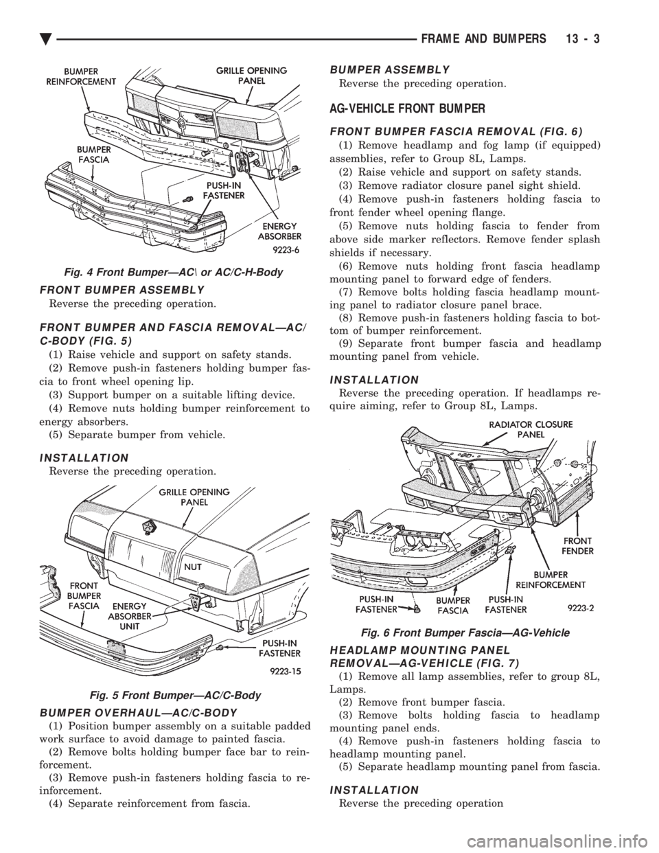
FRONT BUMPER ASSEMBLY
Reverse the preceding operation.
FRONT BUMPER AND FASCIA REMOVALÐAC/ C-BODY (FIG. 5)
(1) Raise vehicle and support on safety stands.
(2) Remove push-in fasteners holding bumper fas-
cia to front wheel opening lip. (3) Support bumper on a suitable lifting device.
(4) Remove nuts holding bumper reinforcement to
energy absorbers. (5) Separate bumper from vehicle.
INSTALLATION
Reverse the preceding operation.
BUMPER OVERHAULÐAC/C-BODY
(1) Position bumper assembly on a suitable padded
work surface to avoid damage to painted fascia. (2) Remove bolts holding bumper face bar to rein-
forcement. (3) Remove push-in fasteners holding fascia to re-
inforcement. (4) Separate reinforcement from fascia.
BUMPER ASSEMBLY
Reverse the preceding operation.
AG-VEHICLE FRONT BUMPER
FRONT BUMPER FASCIA REMOVAL (FIG. 6)
(1) Remove headlamp and fog lamp (if equipped)
assemblies, refer to Group 8L, Lamps. (2) Raise vehicle and support on safety stands.
(3) Remove radiator closure panel sight shield.
(4) Remove push-in fasteners holding fascia to
front fender wheel opening flange. (5) Remove nuts holding fascia to fender from
above side marker reflectors. Remove fender splash
shields if necessary. (6) Remove nuts holding front fascia headlamp
mounting panel to forward edge of fenders. (7) Remove bolts holding fascia headlamp mount-
ing panel to radiator closure panel brace. (8) Remove push-in fasteners holding fascia to bot-
tom of bumper reinforcement. (9) Separate front bumper fascia and headlamp
mounting panel from vehicle.
INSTALLATION
Reverse the preceding operation. If headlamps re-
quire aiming, refer to Group 8L, Lamps.
HEADLAMP MOUNTING PANEL REMOVALÐAG-VEHICLE (FIG. 7)
(1) Remove all lamp assemblies, refer to group 8L,
Lamps. (2) Remove front bumper fascia.
(3) Remove bolts holding fascia to headlamp
mounting panel ends. (4) Remove push-in fasteners holding fascia to
headlamp mounting panel. (5) Separate headlamp mounting panel from fascia.
INSTALLATION
Reverse the preceding operation
Fig. 4 Front BumperÐAC\ or AC/C-H-Body
Fig. 5 Front BumperÐAC/C-Body
Fig. 6 Front Bumper FasciaÐAG-Vehicle
Ä FRAME AND BUMPERS 13 - 3
Page 1764 of 2438
2.2L/2.5L SINGLE POINT FUEL INJECTIONÐSYSTEM OPERATION INDEX
page page
Air Conditioning (A/C) Clutch RelayÐPCM Output.28
Air Conditioning Switch SenseÐPCM Input ..... 26
Auto Shutdown (ASD) Relay and Fuel Pump RelayÐPCM Output ..................... 29
Battery VoltageÐPCM Input ................ 26
Brake SwitchÐPCM Input .................. 26
EVAP Canister Purge SolenoidÐPCM Output . . . 29
CCD Bus .............................. 25
Coolant Temperature SensorÐPCM Input ...... 26
Data Link ConnectorÐPCM Output ........... 30
Distributor (Hall Effect) Pick-UpÐPCM Input .... 26
Electric Electronic Gas RecirculationÐPCM Output.30
Fuel InjectorÐPCM Output ................. 31
Fuel Pressure Regulator ................... 33
General Information ....................... 24
Generator FieldÐPCM Output ............... 31
Heated Oxygen Sensor (O
2Sensor)ÐPCM Input . 27
Idle Air Control MotorÐPCM Output .......... 29 Ignition CoilÐPCM Output
.................. 31
Malfunction Indicator Lamp (Check Engine)ÐPCM Output ............................... 30
Manifold Absolute Pressure (MAP) SensorÐPCM Input ................................ 27
Modes of Operation ....................... 32
Part Throttle Unlock SolenoidÐPCM Output .... 31
Powertrain Control Module ................. 25
Radiator Fan RelayÐPCM Output ............ 31
Speed Control SolenoidsÐPCM Output ........ 31
Speed ControlÐPCM Input ................. 27
System Diagnosis ........................ 25
TachometerÐPCM Output .................. 32
Throttle Body ............................ 33
Throttle Position Sensor (TPS)ÐPCM Input ..... 28
Transaxle Park/Neutral SwitchÐPCM Input ..... 28
Vehicle Speed SensorÐPCM Input ........... 28
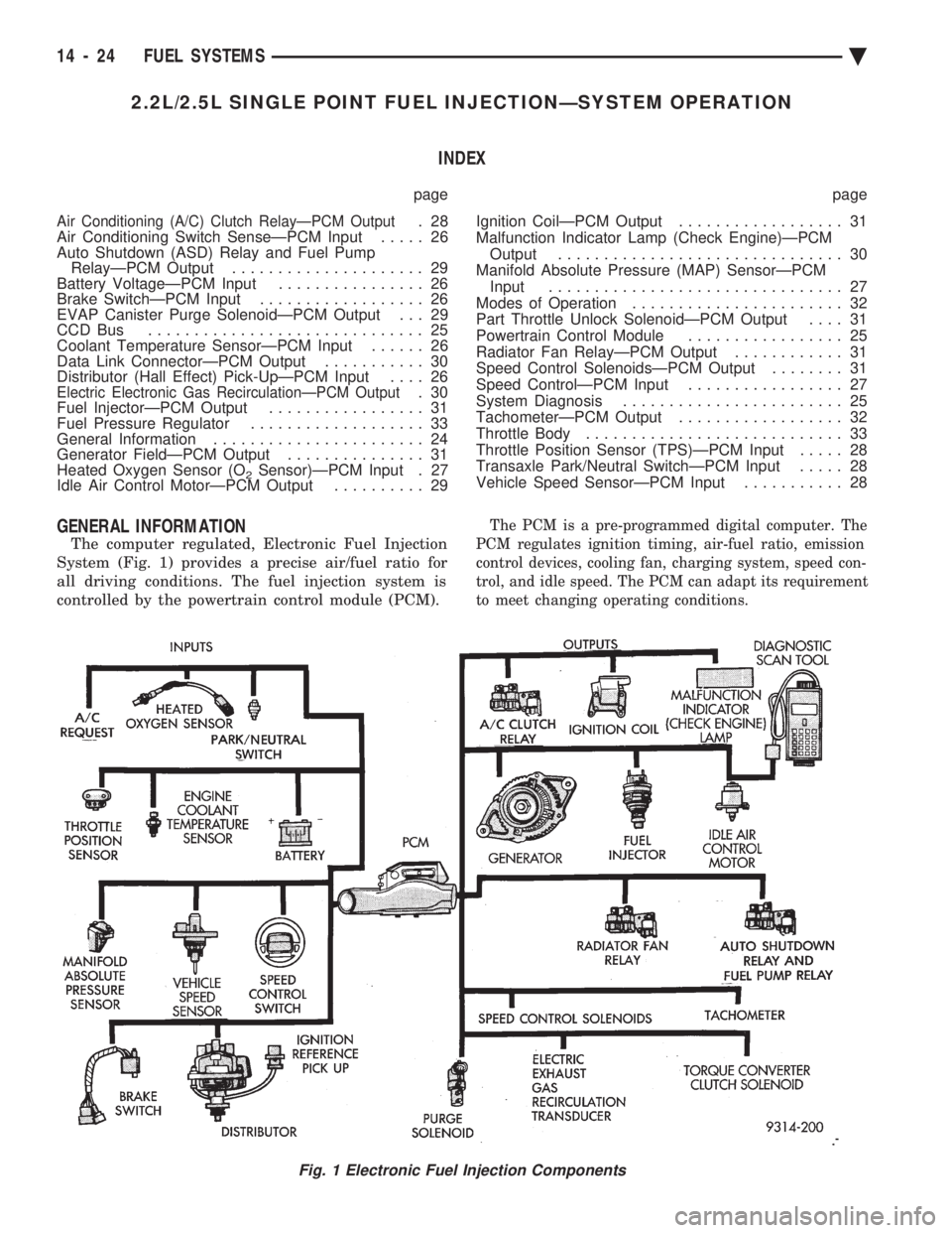
GENERAL INFORMATION
The computer regulated, Electronic Fuel Injection
System (Fig. 1) provides a precise air/fuel ratio for
all driving conditions. The fuel injection system is
controlled by the powertrain control module (PCM).
The PCM is a pre-programmed digital computer. The
PCM regulates ignition timing, air-fuel ratio, emission
control devices, cooling fan, charging system, speed con-
trol, and idle speed. The PCM can adapt its requirement
to meet changing operating conditions.
Fig. 1 Electronic Fuel Injection Components
14 - 24 FUEL SYSTEMS Ä
Page 1765 of 2438
Various sensors provide the inputs necessary for
the PCM to correctly regulate fuel flow at the fuel
injector. These include the manifold absolute pres-
sure, throttle position, oxygen sensor, coolant tem-
perature, and vehicle speed sensors. In addition to
the sensors, various switches and relays provide im-
portant information and system control. The inputs
include the park/neutral switch and air conditioning
clutch switch. The outputs include the auto shutdown
relay and fuel pump relay. All inputs to the PCM are converted into signals.
Based on these inputs the PCM adjusts air-fuel ratio,
ignition timing and other controlled outputs. The
PCM adjusts the air-fuel ratio by changing the injec-
tor pulse width. Injector pulse width is the period of
time the injector is energized.
SYSTEM DIAGNOSIS
The PCM tests many of its own input and output
circuits. If a fault is found in a major system, the in-
formation is stored in memory. Technicians can dis-
play fault information through the instrument panel
Malfunction Indicator lamp (instrument panel Check
Engine lamp) or by connecting the DRBII scan tool.
For diagnostic trouble code information, refer to On
Board Diagnostics in 2.2L/2.5L Single Point Fuel In-
jectionÐGeneral Diagnosis section of this group.
CCD BUS
Various modules exchange information through a
communications port called the CCD Bus. The pow-
ertrain control module (PCM) transmits vehicle load
data on the CCD Bus.
POWERTRAIN CONTROL MODULE
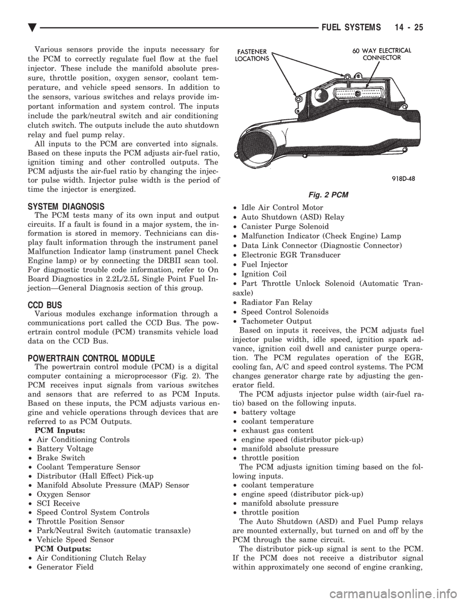
The powertrain control module (PCM) is a digital
computer containing a microprocessor (Fig. 2). The
PCM receives input signals from various switches
and sensors that are referred to as PCM Inputs.
Based on these inputs, the PCM adjusts various en-
gine and vehicle operations through devices that are
referred to as PCM Outputs. PCM Inputs:
² Air Conditioning Controls
² Battery Voltage
² Brake Switch
² Coolant Temperature Sensor
² Distributor (Hall Effect) Pick-up
² Manifold Absolute Pressure (MAP) Sensor
² Oxygen Sensor
² SCI Receive
² Speed Control System Controls
² Throttle Position Sensor
² Park/Neutral Switch (automatic transaxle)
² Vehicle Speed Sensor
PCM Outputs:
² Air Conditioning Clutch Relay
² Generator Field ²
Idle Air Control Motor
² Auto Shutdown (ASD) Relay
² Canister Purge Solenoid
² Malfunction Indicator (Check Engine) Lamp
² Data Link Connector (Diagnostic Connector)
² Electronic EGR Transducer
² Fuel Injector
² Ignition Coil
² Part Throttle Unlock Solenoid (Automatic Tran-
saxle)
² Radiator Fan Relay
² Speed Control Solenoids
² Tachometer Output
Based on inputs it receives, the PCM adjusts fuel
injector pulse width, idle speed, ignition spark ad-
vance, ignition coil dwell and canister purge opera-
tion. The PCM regulates operation of the EGR,
cooling fan, A/C and speed control systems. The PCM
changes generator charge rate by adjusting the gen-
erator field. The PCM adjusts injector pulse width (air-fuel ra-
tio) based on the following inputs.
² battery voltage
² coolant temperature
² exhaust gas content
² engine speed (distributor pick-up)
² manifold absolute pressure
² throttle position
The PCM adjusts ignition timing based on the fol-
lowing inputs.
² coolant temperature
² engine speed (distributor pick-up)
² manifold absolute pressure
² throttle position
The Auto Shutdown (ASD) and Fuel Pump relays
are mounted externally, but turned on and off by the
PCM through the same circuit. The distributor pick-up signal is sent to the PCM.
If the PCM does not receive a distributor signal
within approximately one second of engine cranking,
Fig. 2 PCM
Ä FUEL SYSTEMS 14 - 25
Page 1768 of 2438

TRANSAXLE PARK/NEUTRAL SWITCHÐPCM
INPUT
The park/neutral switch is located on the auto-
matic transaxle housing (Fig. 7). Manual transaxles
do not use park neutral switches. The switch pro-
vides an input to the PCM. The input indicates
whether the automatic transaxle is in Park, Neutral,
or a drive gear selection. This input is used to deter-
mine idle speed (varying with gear selection), fuel in-
jector pulse width, and ignition timing advance. The
park neutral switch is sometimes referred to as the
neutral safety switch.
THROTTLE POSITION SENSOR (TPS)ÐPCM INPUT
The Throttle Position Sensor (TPS) is mounted on
the throttle body and connected to the throttle blade
shaft (Fig. 8). The TPS is a variable resistor. The
sensor provides an input signal (voltage) to the PCM
representing throttle blade position. As the position
of the throttle blade changes, the resistance of the
TPS changes.
The PCM supplies approximately 5 volts to the
TPS. The TPS output voltage (input signal to the
PCM) represents the throttle blade position. The
PCM receives an input signal voltage from the TPS
varying in an approximate range of from 1 volt at
minimum throttle opening (idle) to 4 volts at wide open throttle. Along with inputs from other sensors,
the PCM uses the TPS input to determine current
engine operating conditions. The PCM adjusts fuel
injector pulse width and ignition timing based on
these inputs.
VEHICLE SPEED SENSORÐPCM INPUT
The vehicle speed sensor is located in the transaxle
extension housing (Fig. 9). The sensor input is used
by the PCM to determine vehicle speed and distance
traveled.
The speed sensor generates 8 pulses per sensor rev-
olution. These signals, along with a closed throttle
signal from the TPS, determine if a closed throttle
deceleration or normal idle condition (vehicle
stopped) exists. Under deceleration conditions, the
PCM adjusts the idle air control motor to maintain a
desired MAP value. Under idle conditions, the PCM
adjusts the idle air control motor to maintain a de-
sired engine speed.
AIR CONDITIONING (A/C) CLUTCH RELAYÐPCM
OUTPUT
The PCM operates the air conditioning clutch relay
ground circuit. The radiator fan relay supplies bat-
tery power to the solenoid side of the A/C clutch re-
lay. The air conditioning clutch relay will not
energize unless the radiator fan relay energizes. The
PCM energizes the radiator fan relay when the air
conditioning or defrost switch is put in the ON posi-
tion and the low pressure and high pressure switches
close. With the engine operating, the PCM cycles the air
conditioning clutch on and off when the A/C switch
closes with the blower motor switch in the on posi-
tion. When the PCM senses low idle speeds or wide
open throttle through the throttle position sensor, it
de-energizes the A/C clutch relay. The relay contacts
open, preventing air conditioning clutch engagement.
Fig. 7 Park/Neutral Switch
Fig. 8 Throttle Position Sensor
Fig. 9 Vehicle Distance (Speed) SensorÐTypical
14 - 28 FUEL SYSTEMS Ä
Page 1771 of 2438
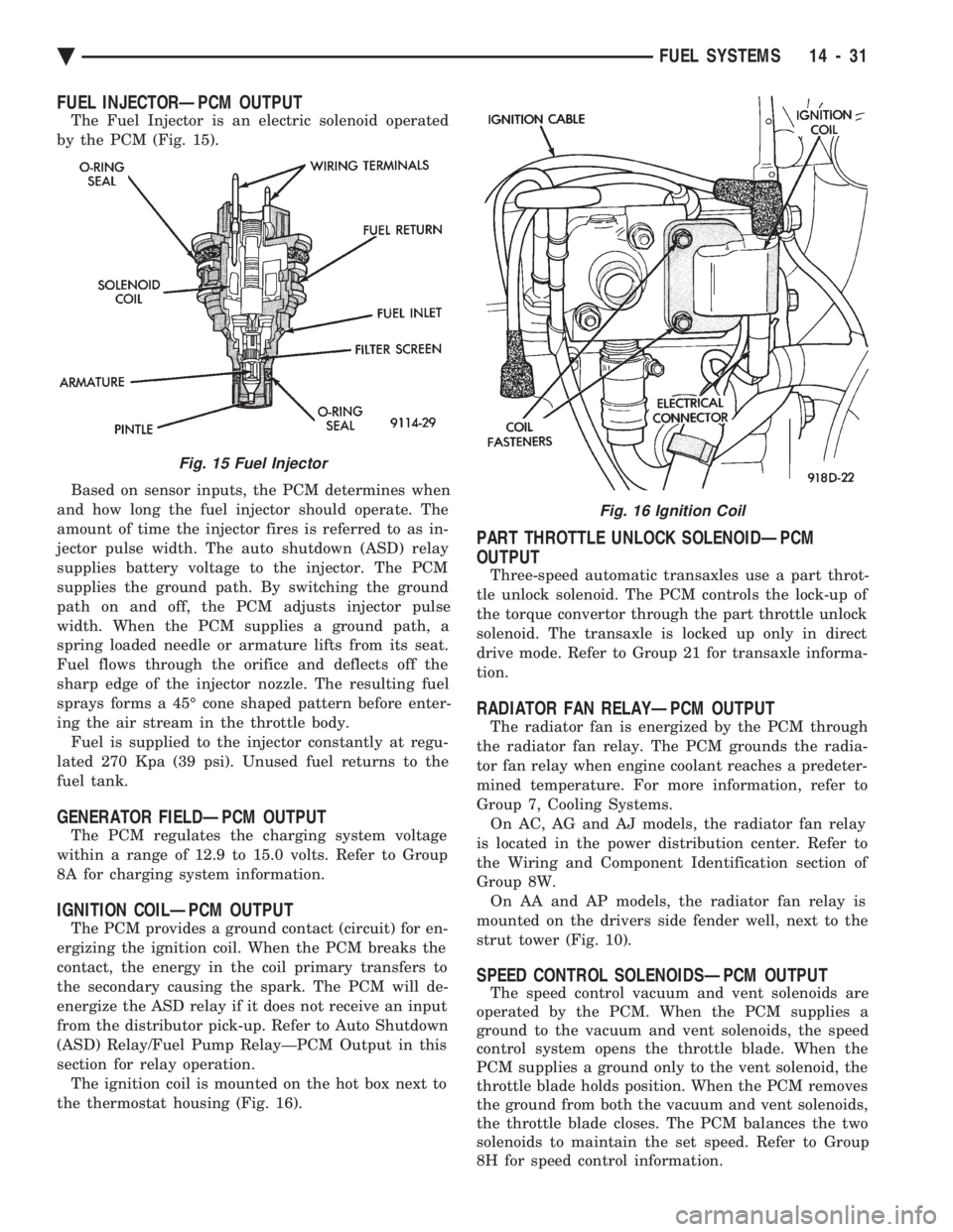
FUEL INJECTORÐPCM OUTPUT
The Fuel Injector is an electric solenoid operated
by the PCM (Fig. 15).
Based on sensor inputs, the PCM determines when
and how long the fuel injector should operate. The
amount of time the injector fires is referred to as in-
jector pulse width. The auto shutdown (ASD) relay
supplies battery voltage to the injector. The PCM
supplies the ground path. By switching the ground
path on and off, the PCM adjusts injector pulse
width. When the PCM supplies a ground path, a
spring loaded needle or armature lifts from its seat.
Fuel flows through the orifice and deflects off the
sharp edge of the injector nozzle. The resulting fuel
sprays forms a 45É cone shaped pattern before enter-
ing the air stream in the throttle body. Fuel is supplied to the injector constantly at regu-
lated 270 Kpa (39 psi). Unused fuel returns to the
fuel tank.
GENERATOR FIELDÐPCM OUTPUT
The PCM regulates the charging system voltage
within a range of 12.9 to 15.0 volts. Refer to Group
8A for charging system information.
IGNITION COILÐPCM OUTPUT
The PCM provides a ground contact (circuit) for en-
ergizing the ignition coil. When the PCM breaks the
contact, the energy in the coil primary transfers to
the secondary causing the spark. The PCM will de-
energize the ASD relay if it does not receive an input
from the distributor pick-up. Refer to Auto Shutdown
(ASD) Relay/Fuel Pump RelayÐPCM Output in this
section for relay operation. The ignition coil is mounted on the hot box next to
the thermostat housing (Fig. 16).
PART THROTTLE UNLOCK SOLENOIDÐPCM
OUTPUT
Three-speed automatic transaxles use a part throt-
tle unlock solenoid. The PCM controls the lock-up of
the torque convertor through the part throttle unlock
solenoid. The transaxle is locked up only in direct
drive mode. Refer to Group 21 for transaxle informa-
tion.
RADIATOR FAN RELAYÐPCM OUTPUT
The radiator fan is energized by the PCM through
the radiator fan relay. The PCM grounds the radia-
tor fan relay when engine coolant reaches a predeter-
mined temperature. For more information, refer to
Group 7, Cooling Systems. On AC, AG and AJ models, the radiator fan relay
is located in the power distribution center. Refer to
the Wiring and Component Identification section of
Group 8W. On AA and AP models, the radiator fan relay is
mounted on the drivers side fender well, next to the
strut tower (Fig. 10).
SPEED CONTROL SOLENOIDSÐPCM OUTPUT
The speed control vacuum and vent solenoids are
operated by the PCM. When the PCM supplies a
ground to the vacuum and vent solenoids, the speed
control system opens the throttle blade. When the
PCM supplies a ground only to the vent solenoid, the
throttle blade holds position. When the PCM removes
the ground from both the vacuum and vent solenoids,
the throttle blade closes. The PCM balances the two
solenoids to maintain the set speed. Refer to Group
8H for speed control information.
Fig. 15 Fuel Injector
Fig. 16 Ignition Coil
Ä FUEL SYSTEMS 14 - 31
Page 1777 of 2438
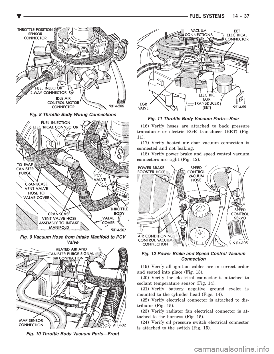
(16) Verify hoses are attached to back pressure
transducer or electric EGR transducer (EET) (Fig.
11). (17) Verify heated air door vacuum connection is
connected and not leaking. (18) Verify power brake and speed control vacuum
connectors are tight (Fig. 12).
(19) Verify all ignition cables are in correct order
and seated into place (Fig. 13). (20) Verify the electrical connector is attached to
coolant temperature sensor (Fig. 14). (21) Verify battery negative ground eyelet is
mounted to the cylinder head (Figs. 14). (22) Verify electrical connector is attached to dis-
tributor (Fig. 15). (23) Verify radiator fan electrical connector is at-
tached to the harness (Fig. 15). (24) Verify oil pressure switch electrical connector
is attached to the switch (Fig. 15).
Fig. 9 Vacuum Hose from Intake Manifold to PCV Valve
Fig. 10 Throttle Body Vacuum PortsÐFront
Fig. 8 Throttle Body Wiring ConnectionsFig. 11 Throttle Body Vacuum PortsÐRear
Fig. 12 Power Brake and Speed Control VacuumConnection
Ä FUEL SYSTEMS 14 - 37