1993 CHEVROLET DYNASTY charging
[x] Cancel search: chargingPage 691 of 2438
REAR WINDOW DEFOGGER
CONTENTS
page page
CONTROL SWITCH/TIMER RELAY MODULE . . 1
GENERAL INFORMATION .................. 1REPAIR GRID LINES, TERMINALS AND PIGTAILS.3
SERVICE PROCEDURES ................... 1
GENERAL INFORMATION
For proper operation of the Rear Window Defogger
system refer to the Owner's Manual. Vehicles equipped with an electrically heated rear
window defogger also have a 40/90 amp generator. The system consists of a rear glass with two verti-
cal bus bars and a series of electrically connected
grid lines fired on the inside surface. A control
switch and a timer relay combined into a single as-
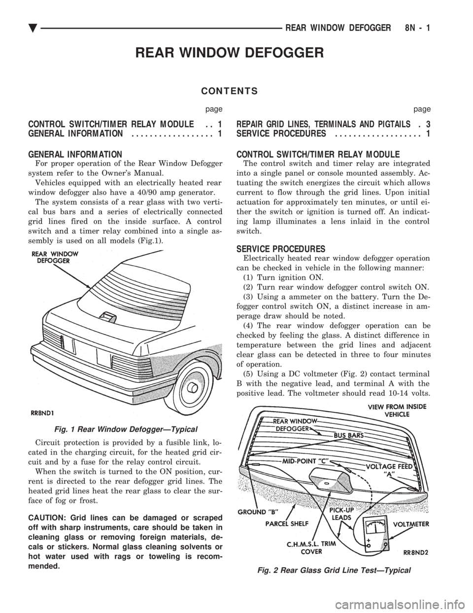
sembly is used on all models (Fig.1).
Circuit protection is provided by a fusible link, lo-
cated in the charging circuit, for the heated grid cir-
cuit and by a fuse for the relay control circuit. When the switch is turned to the ON position, cur-
rent is directed to the rear defogger grid lines. The
heated grid lines heat the rear glass to clear the sur-
face of fog or frost.
CAUTION: Grid lines can be damaged or scraped
off with sharp instruments, care should be taken in
cleaning glass or removing foreign materials, de-
cals or stickers. Normal glass cleaning solvents or
hot water used with rags or toweling is recom-
mended.
CONTROL SWITCH/TIMER RELAY MODULE
The control switch and timer relay are integrated
into a single panel or console mounted assembly. Ac-
tuating the switch energizes the circuit which allows
current to flow through the grid lines. Upon initial
actuation for approximately ten minutes, or until ei-
ther the switch or ignition is turned off. An indicat-
ing lamp illuminates a lens inlaid in the control
switch.
SERVICE PROCEDURES
Electrically heated rear window defogger operation
can be checked in vehicle in the following manner: (1) Turn ignition ON.
(2) Turn rear window defogger control switch ON.
(3) Using a ammeter on the battery. Turn the De-
fogger control switch ON, a distinct increase in am-
perage draw should be noted. (4) The rear window defogger operation can be
checked by feeling the glass. A distinct difference in
temperature between the grid lines and adjacent
clear glass can be detected in three to four minutes
of operation. (5) Using a DC voltmeter (Fig. 2) contact terminal
B with the negative lead, and terminal A with the
positive lead. The voltmeter should read 10-14 volts.
Fig. 1 Rear Window DefoggerÐTypical
Fig. 2 Rear Glass Grid Line TestÐTypical
Ä REAR WINDOW DEFOGGER 8N - 1
Page 753 of 2438

is non-standard the main wire color will have a slash
(/) after it followed by the tracer color.
CIRCUIT IDENTIFICATION
All circuits in the diagrams use an alpha/numeric
code to identify the wire and its function. To identify
which circuit code applies to a system, refer to the
Circuit Identification Code Chart. This chart shows
the main circuits only and does not show the second-
ary codes that may apply to some models.
LOCATING A SYSTEM
To locate a system or component in the diagrams,
refer to the alphabetical index at the front of the di-
agrams. Determine the diagram sheet number. Sheet
numbers are located at the lower right or left hand
corner of each sheet. Page numbers at the top of
the page do not apply to diagram sheets. The diagram index identifies the main system and
all components in that system. There are also sec-
tions of the index that identify specific components
only (for example modules, lamps, etc.). Refer to a
components name in the index if you are unclear as
to what a system may be called. Diagram pages are arranged starting with the bat-
tery and fuses. Then working into charging, starting,
and ignition systems. After this they start at the
front of the vehicle and work to rear of the vehicle.
The diagrams end with connector identification
pages.
COMPONENT IDENTIFICATION
When looking for a components location on the ve-
hicle refer to the wiring and components section.
This section shows the wire harness routing and the
components location in the vehicle. To use this sec-
tion refer to the wiring diagrams for the location of
the component. Then use the component identifica-
tion index to locate the proper figure number.
SPLICE LOCATIONS
Splices are indicated in the diagrams by a diamond
with a splice circuit code within it (Fig. 9 example 1).
If there is more than one splice per circuit a small
box will be connected to it with the splice number in
it (Fig. 9 example 2). To locate a splice in the wiring harness determine
the splice number from the wiring diagrams then re-
fer to the splice location index. This section shows
the general location of the splice in the harness.
Fig. 6 Wiring Diagram Page Sample
Fig. 7 Wire Color Code Identification
Fig. 8 Wire Color Code Chart
Ä GENERAL INFORMATION 8W - 3
Page 931 of 2438

WIRING DIAGRAMS AA-BODY
INDEX
Wiring Diagram
Name Sheet Number
Airbag System ...............................47
Clockspring ...............................47
Diagnostic Module ..........................47
Interface Grommet ..........................47
Sensor-Left ...............................47
Sensor-Right ..............................47
Squibb ..................................47
Air Conditioning Compressor ...................32, 33
Air Conditioning System (2.5L Engine) ...............71
A/C Cycling Switch ..........................71
Blower Motor ..............................71
Blower Switch .............................71
Control Switch .............................71
Damped Pressure Switch ......................71
Defrost Switch .............................71
Illumination Lamp ...........................71
Resistor .................................71
Air Conditioning System (3.0L Engine) ...............72
A/C Switch ...............................72
Blower Motor ..............................72
Blower Switch .............................72
Control Switch .............................72
Damped Pressure Switch ......................72
Defrost Switch .............................72
High Pressure Switch ........................72
Illumination Lamp ...........................72
Resistor .................................72
Anti-Lock Brake System .................41, 42, 43, 44
ABS Pump Motor Relay .......................41
ABS System Relay ..........................43
ABS Warning Lamp Relay ......................43
Brake Switch ..............................44
Controller ....................... .41, 42, 43, 44
Hydraulic Modulator .........................41
Ignition Switch .............................44
Park Brake Switch ...........................44
Wheel Sensors .............................42
Ash Receiver Lamp ...........................52
Automatic Shut-down Relay .................14, 20, 28
Automatic Transmission Park/Neutral Position and Back-Up Lamp Switch ...............................9
Back-Up Lamp Switch ..........................9
Battery ............................1,5,7,39,40
Blower Motor-A/C ............................71
Blower Motor-Heater ...........................71
Brake Switch ...............................44
Brake Warning Lamp Switch ......................11
Bulkhead Disconnect (50-Way) ................112, 113
Center High Mounted Stop Lamp ..........94, 98, 102, 105
Charging System (2.5L) ........................5,6
Battery ...................................5
Generator .................................6Wiring Diagram
Name Sheet Number
Heated Rear Window Switch .....................5
Charging System (3.0L) ........................7,8
Battery ....................................7
Generator .................................8
Ignition Off-Draw Connector .....................7
Cigar Lighter ................................45
Cigar Lighter Lamp ............................52
Circuit Breaker (30 Amp) Fuseblock Cavity #10 .......67, 82
Circuit Breaker (30 Amp) Fuseblock Cavity #13 . . .2, 66, 67, 86
Clockspring ............................. .47, 59
Cluster Printed Circuit Board .................119, 120
Cluster Printed Circuit Board Connectors .............118
Courtesy Lamps .............................76
Daytime Running Light Module ....................57
Deck Lid Ajar Switch ..........................78
Dimmer Switch-Headlamp .....................1,50
Distributor ......................... .15, 21, 22, 27
EGR Solenoid ...............................24
Electrically Heated Rear Window ...................84
Heated Rear Window .........................84
Switch ..................................84
Timer ...................................84
Electronically Tuned Stereo Radio without Name Brand Speakers ................................87
Electronically Tuned Stereo Radio with Name Brand Speakers ................................89
Speaker Choke .............................89
Speaker Relay .............................89
Electronic Cluster ........................... .121
Engine Coolant Sensor ................... .15, 21, 27
Engine Oil and Temperature Warning System (2.5L) .......39
Engine Oil and Temperature Warning System (3.0L) .......40
Engine Oil Pressure Switch/Sending Unit ...........39, 40
Engine Temperature Sending Unit ................39, 40
Engine Starter System (2.5L Engine & 3.0L ATX) .......9,10
Automatic Transmission Park/Neutral Position Switch .....9
Backup Lamp Switch ..........................9
EMCC Solenoid .............................9
Engine Starter Relay ..........................9
Manual Transmission Back-Up Lamp Switch ...........9
Permanent Magnet Engine Starter Motor .............9
Engine Temperature Sending Unit ................39, 40
Exhaust Gas Recirculation Diagnostic Solenoid ........13, 24
Fan Control System with A/C and Heater System (2.5L) ....32
A/C Compressor ............................32
A/C Compressor Clutch Relay ...................32
A/C High Pressure Switch ......................32
Fan Control Relay ...........................32
Radiator Fan Motor ..........................32
Fan Control System with A/C and Heater System (3.0L) ....33
A/C Conditioning Compressor ...................33
A/C Compressor Clutch Relay ...................33
Ä WIRING DIAGRAMS AA-BODY 8W - 181
Page 1064 of 2438
Wiring Diagram
Name Sheet Number
Relay Bank ............................. .106
Blower Slide Control ...........................51
Bulkhead Disconnect (50 Way) ................181, 182
Bulkhead Disconnect (50-Way) (2.5L Engine) .......183, 184
Bulkhead Disconnect (50-Way) (3.0L Engine) .......185, 186
Bulkhead Disconnect (50-Way) (3.3L & 3.8L Engine) ......................... .187, 188
Camshaft Position Sensor .......................28
Crankshaft Position Sensor .......................28
Cellular Phone System ........................ .126
Antenna ............................... .126
Center Phone ............................ .126
External Speaker .......................... .126
Microphone ............................. .126
Transmitter/Receiver Unit .................... .126
Visor Phone ............................. .126
Charging System (2.5L Engine) ...................5,6
Battery ...................................5
Generator .................................6
Power Distribution Center .......................6
Charging System (3.0L Engine) ...................7,8
Battery ...................................7
Generator .................................8
Power Distribution Center .......................8
Charging System (3.3L & 3.8L Engine) .............9,10
Battery ...................................9
Generator ................................10
Power Distribution Center ......................10
Cigar Lighter .......................... .111, 112
Circuit Breakers Concealed Headlamps .......................2,68
Power Door Locks ........................2,139
Power Seats ............................2,149
Power Windows .........................3,158
Compressor Motor ........................ .40, 42
Concealed Headlamp Controls .....................68
Circuit Breaker .............................68
Headlamp Door Motor ........................68
Headlamp Door Relays ........................68
Headlamp Relay ............................68
Relay Bank ...............................68
Courtesy Lamp System .................87, 88, 89, 90
Left Front Door Courtesy Lamp ..................87
Left Front Door Jamb Switch ....................87
Left Illuminated Visor Vanity Mirror ................89
Left Illuminated Visor Vanity Mirror Switch ...........89
Left Lamp and Switch ........................89
Left Rear Door Courtesy Lamp ...................87
Left Rear Door Jamb Switch ....................87
Left Rear Quarter Reading Lamp ..................90
Right Front Door Courtesy Lamp .................88
Right Front Door Jamb Switch ...................88
Right Illuminated Visor Vanity Mirror ...............89
Right Illuminated Visor Vanity Mirror Switch ..........89
Right Lamp and Switch .......................89
Right Rear Door Courtesy Lamp ..................88
Right Rear Door Jamb Switch ...................88Wiring Diagram
Name Sheet Number
Right Rear Quarter Reading Lamp .................90
Trunk Lamp ...............................90
Data Link Connectors ..........14, 23, 100, 103, 106, 110,
130, 134, 136
Deck Lid Release and Deck Lid Pull-Down System . . . .159, 160
Deck Lid Pull-Down Unit ..................... .160
Deck Lid Release Solenoid .................159, 160
Deck Lid Release Solenoid/Pull-Down Key Cylinder Switch ............................... .160
Mercury Switch .......................... .159
Underhood Light .......................... .159
Dimmer Switch-Optical Horn ....................1,66
Distributor .............................. .17, 19
Door Ajar System w/Electronic Cluster ...............92
Left Front Door Ajar Switch .....................92
Left Rear Door Ajar Switch .....................92
Right Front Door Ajar Switch ....................92
Right Rear Door Ajar Switch ....................92
Door Ajar System w/Mechanical Cluster and Visual Mess Ctr ...............................93
Left Front Door Ajar Switch .....................93
Left Rear Door Ajar Switch .....................93
Right Front Door Ajar Switch ....................93
Right Rear Door Ajar Switch ....................93
Door Ajar System w/Mechanical Cluster w/o Visual Mess Ctr ...............................94
Left Front Door Ajar Switch .....................94
Left Rear Door Ajar Switch .....................94
Right Front Door Ajar Switch ....................94
Right Rear Door Ajar Switch ....................94
Door Electrical Ground Systems ...................165
Door Jamb Courtesy Lamp Switches ..............87, 88
Door Lock System ....................... .139, 140
Circuit Breaker ........................... .139
Connector and Door Lock Switch Function .......139, 140
Door Lock Relay .......................... .140
Door Unlock Relay ......................... .140
Left Front Door Lock Motor ................... .139
Left Front Door Lock Switch ...................139
Left Rear Door Lock Motor ................... .139
Relay Bank ............................. .139
Right Front Door Lock Motor ...................140
Right Front Door Lock Switch ..................140
Right Rear Door Lock Motor ...................140
Exhaust Gas Recirculation Solenoid ............14, 21, 26
Electronically Tuned Stereo Radio ..............119, 120
Left Door Speaker ......................... .120
Left Rear Speaker ......................... .120
Right Door Speaker ........................ .120
Right Rear Speaker ........................ .120
Electronically Tuned Stereo Radio with RS Amplifier ....................... .121, 122, 123
Left Door Speaker ......................... .123
Left Front Speaker ......................... .123
Left Rear Speaker ......................... .123
Right Door Speaker ........................ .123
Right Front Speaker ........................ .123
Right Rear Speaker ........................ .123
8W - 314 WIRING DIAGRAMS AC-AY BODY Ä
Page 1283 of 2438
WIRING DIAGRAMS AG-AJ BODY
ALPHABETICAL INDEX
Wiring Diagram
Name Sheet Number
A/C Compressor Clutch .........................89
A/C and Heater System ..................... .91, 92
A/C Compressor Clutch Relay ...................91
A/C Low Pressure Switch ......................91
A/C High Pressure Switch ......................92
A/C Cycling Switch ..........................92
ABS Warning Lamp Diode .......................69
Airbag System ........................... .84, 85
Clock Spring ..............................84
Diagnostic Module ..........................84
Interface Grommet ..........................85
Left Airbag Sensor ..........................85
Right Airbag Sensor .........................85
Squib (Airbag Igniter) ........................84
Air Conditioning System ........................90
A/C Blower Motor ...........................90
A/C/Heater Blower Motor Resistor .................90
A/C Switch ...............................90
Blower Switch .............................90
Defrost Switch .............................90
Illumination Lamps Switch .....................90
Alarm, Security Module ....................... .127
Ambient Air Temperature Sensor ...............117, 119
Anti-Lock Brake System (Except Turbo 3) .............170
Anti-Lock Brake System Controller ..........68, 69, 70, 71
Anti-Lock Brake System .................68, 69, 70, 71
ABS Controller .................... .68, 69, 70, 71
ABS Hydraulic Modulator ......................68
ABS Pump Motor Relay .......................68
ABS System Relay ..........................69
ABS Warning Lamp Diode ......................69
ABS Warning Switch Lamp Switch ................70
Brake Switch ..............................70
Left Front Wheel Sensor .......................71
Left Rear Wheel Sensor .......................71
Park Brake Switch ...........................70
Right Front Wheel Sensor ......................71
Right Rear Wheel Sensor ......................71
Automatic Shutdown Relay ..................20, 27, 33
Battery ...........................1,9,11,53,56
Body Computer ......................... .165, 166
Body Computer #1 ............................40
Body Computer (Mechanical Cluster) ..............79, 80
Body Computer #2 ............................40
Body Computer (Electronic Cluster) ...............81, 82
Body Wiring to Left Instrument Panel ...............147
Body Wiring to Right Instrument Panel ...........150, 151
Bulkhead Disconnect (50-Way) ................153, 154
Center High Mounted Stop Lamp (AG) ...............140
Center High Mounted Stop Lamp (J-21) ..............141
Center High Mounted Stop Lamp (J-27) ..............142
Charging System (2.5L and Turbo) ................9,10Wiring Diagram
Name Sheet Number
Battery ...................................9
Data Link Connector ..........................9
Generator ................................10
Power Distribution Center ....................9,10
Powertrain Control Module ......................9
Charging System (3.0L) ..................... .11, 12
Battery ..................................11
Generator ................................12
Power Distribution Center .................. .11, 12
Cigar Lighter ................................51
Circuit Breakers (Fuse Cavity #2) ...........8,42,110, 111
Circuit Breakers (Fuse Cavity #3) ..............5,53,116
Clockspring .......................... .59, 65, 84
Clutch Pedal Position Jumper ..................13, 15
Clutch Pedal Position Switch .....................14
Combo Flasher ..............................56
Data Link Connector ..................9,19,25,34,72
Daytime Running Lights Module Connector ............173
Decklid Lock Sense Switch ..................... .102
Dimming Interior Lamps & Headlamp Switch .........51, 52
Ash Receiver Lamp ..........................51
Cluster Lamps .............................52
Cigar Lighter ..............................51
Console Switch Module .......................51
A/C Heater Control Switch Lamp .................52
Headlamp Switch ...........................51
Fog Lamp Switch ...........................51
Fuse Panel Switch ...........................51
Left Pod Lamps ............................51
Left Switch Pod ............................51
Transmission Range Lamp .....................51
Diode ....................................89
Diode Package ....................... .83, 102, 104
Distributor .............................. .21, 26
Dome and Courtesy Lamps (AG) ...............125, 126
Cargo Lamp ............................. .126
Dome Lamp ............................. .126
Front Reading Lamps ....................... .126
Front Reading Lamp Switch ................... .126
Glove Box Lamp & Switch .................... .125
Halo Light .............................. .125
Liftgate Ajar Switch ........................ .125
Vanity Mirror Lamps ....................... .126
Vanity Mirror Lamp Switch ................... .126
Dome, Reading and Courtesy Lamps (J-27 Only) .....121, 122
Courtesy Lamp ........................... .121
Decklid Ajar Switch ........................ .122
Glove Box Lamp .......................... .121
Halo Light .............................. .121
Left Door Courtesy Lamp .................... .122
Rear Mirror Courtesy Lamp ................... .122
Right Door Courtesy Lamp ................... .121
Ä WIRING DIAGRAMS AG-AJ BODY 8W - 533
Page 1467 of 2438
WIRING DIAGRAMS AP BODY D-P
ALPHABETICAL INDEX
Wiring Diagram
Name Sheet Number
ABS Hydraulic Modulator Unit .....................27
ABS Pump Motor Relay .........................27
ABS System Controller ................... .26, 27, 28
ABS System Relay ............................28
ABS Yellow Light Relay .........................28
A/C and Heater System ..................... .47, 48
A/C Cycling Switch ..........................48
A/C High Pressure Switch ......................48
A/C Low Pressure Switch ......................48
Blower Motor ..............................47
Blower Switch .............................47
Defrost Switch .............................47
Illumination Lamp ...........................47
Resistor .................................48
A/C Compressor Clutch Relay .....................50
Airbag Diagnostic Module Connector ................78
Airbag System ...............................35
Clockspring ...............................35
Diagnostic Module ..........................35
Sensors .................................35
Squibb (Airbag Igniter) ........................35
Anti-Lock Braking System ..................26, 27, 28
Data Link Connector .........................27
Hydraulic Modulator Unit ......................27
Pump Motor Relay ..........................27
System Controller ..................... .26, 27, 28
System Relay ..............................28
Wheel Sensors .............................26
Yellow Light Relay ..........................28
Anti-Lock Brake System Controller Connector ...........90
Ash Receiver Lamp ...........................37
Automatic Shut Down Relay 2.2L E.F.I. .............2,14
Automatic Shut Down Relay 2.5L E.F.I. .............2,14
Automatic Shut Down Relay 3.0L .................2,22
Back-Up Lamp Relay ..........................23
Back-Up Lamp Switch .......................7,8,9
Battery .................................1,3,5
Brake Warning Lamp Switch ......................11
Body to Instrument Panel Wiring Left ................87
Cargo Lamp ................................40
Center High Mounted Stop Lamp ................70, 72
Charging System .........................3,4,5,6
Battery .................................3,5
Generator ...............................4,6
Ignition Off Draw Connector ...................3,5
Chime, Key-In, Seat Belt Warning, Headlamp On .........43
Cigar Lighter ................................37
Cigar Lighter Lamp ............................37
Circuit Breakers Headlamp Switch ...........................36
Cavity #8 ..........................2,11,57,58
Cavity #11 ..............................1,60Wiring Diagram
Name Sheet Number
Clockspring .......................... .29, 35, 42
Clutch Pedal Position Jumper ...................8,10
Clutch Pedal Position Switch .....................7,9
Courtesy Lamps .............................72
Data Link Connector ..................... .13, 22, 27
Daytime Running Lamp Jumper ....................30
Daytime Running Lamp Module ....................30
Daytime Running Lights Module Connector ............84
Defrost Switch ..............................47
Dimmer Switch\eadlamp .......................1,36
Dimmer Switch-Optical Horn ....................1,36
Diode 49
Distributor 2.2L, 2.5L ..........................15
Distributor 3.0L ..............................18
Distributor Ignition Coil ..................... .14, 22
Dome Lamp System ....................... .39, 40
Cargo Lamp ..............................40
Dome Lamp ..............................40
Glove Box Lamp ............................39
Glove Box Lamp Switch .......................39
Left Front Door Jamb Switch ....................39
Left Rear Door Jamb Switch ....................40
Liftgate Latch Switch .........................40
Right Front Door Jamb Switch ...................39
Right Rear Door Jamb Switch ...................40
Door and Rear Speakers (Radio) ...................66
Door Jamb Switches ....................... .39, 40
Door Lock System-2 Door .................... .61, 62
Door Lock System-4 Door .................... .63, 64
Engine Coolant Temperature Sending Unit .............12
Engine Coolant Temperature Sensor 2.2L ..............15
Engine Coolant Temperature Sensor 2.5L ..............15
Engine Coolant Temperature Sensor 3.0L ..............18
Engine Oil Pressure Sending Unit/Switch ..............12
Engine Oil Pressure Switch .......................12
Engine Oil Pressure and Temperature System ...........12
Engine to Instrument Panel Wiring ..................86
Engine Starter System ....................7,8,9,10
Engine Starter System (Automatic Transmission) .....2,8,10
Back-Up Lamp Switch .........................8
Clutch Pedal Position Jumper ..................8,10
Engine Starter Motor .......................8,10
Engine Starter Relay ........................8,10
Park/Neutral Position Switch .....................8
Transmission EMCC Solenoid ....................8
Engine Starter System (Manual Transmission) ........2,7,9
Back-Up Lamp Switch .......................7,9
Clutch Pedal Position Switch ...................7,9
Engine Starter Motor ........................7,9
Engine Starter Relay ........................7,9
Squib Igniter (Airbag) ........................35
Exhaust Gas Recirculation Solenoid 2.2L ..............13
Ä WIRING DIAGRAMS AP BODY D-P 8W - 717
Page 1764 of 2438
2.2L/2.5L SINGLE POINT FUEL INJECTIONÐSYSTEM OPERATION INDEX
page page
Air Conditioning (A/C) Clutch RelayÐPCM Output.28
Air Conditioning Switch SenseÐPCM Input ..... 26
Auto Shutdown (ASD) Relay and Fuel Pump RelayÐPCM Output ..................... 29
Battery VoltageÐPCM Input ................ 26
Brake SwitchÐPCM Input .................. 26
EVAP Canister Purge SolenoidÐPCM Output . . . 29
CCD Bus .............................. 25
Coolant Temperature SensorÐPCM Input ...... 26
Data Link ConnectorÐPCM Output ........... 30
Distributor (Hall Effect) Pick-UpÐPCM Input .... 26
Electric Electronic Gas RecirculationÐPCM Output.30
Fuel InjectorÐPCM Output ................. 31
Fuel Pressure Regulator ................... 33
General Information ....................... 24
Generator FieldÐPCM Output ............... 31
Heated Oxygen Sensor (O
2Sensor)ÐPCM Input . 27
Idle Air Control MotorÐPCM Output .......... 29 Ignition CoilÐPCM Output
.................. 31
Malfunction Indicator Lamp (Check Engine)ÐPCM Output ............................... 30
Manifold Absolute Pressure (MAP) SensorÐPCM Input ................................ 27
Modes of Operation ....................... 32
Part Throttle Unlock SolenoidÐPCM Output .... 31
Powertrain Control Module ................. 25
Radiator Fan RelayÐPCM Output ............ 31
Speed Control SolenoidsÐPCM Output ........ 31
Speed ControlÐPCM Input ................. 27
System Diagnosis ........................ 25
TachometerÐPCM Output .................. 32
Throttle Body ............................ 33
Throttle Position Sensor (TPS)ÐPCM Input ..... 28
Transaxle Park/Neutral SwitchÐPCM Input ..... 28
Vehicle Speed SensorÐPCM Input ........... 28
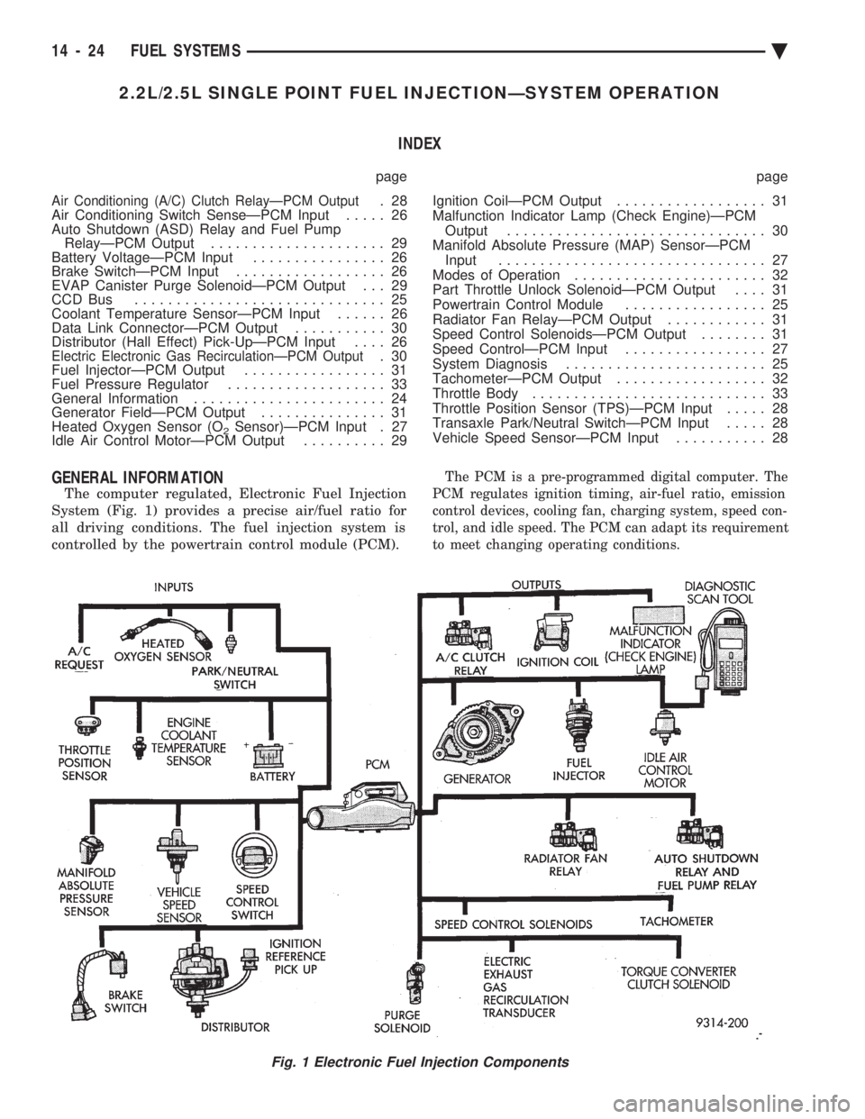
GENERAL INFORMATION
The computer regulated, Electronic Fuel Injection
System (Fig. 1) provides a precise air/fuel ratio for
all driving conditions. The fuel injection system is
controlled by the powertrain control module (PCM).
The PCM is a pre-programmed digital computer. The
PCM regulates ignition timing, air-fuel ratio, emission
control devices, cooling fan, charging system, speed con-
trol, and idle speed. The PCM can adapt its requirement
to meet changing operating conditions.
Fig. 1 Electronic Fuel Injection Components
14 - 24 FUEL SYSTEMS Ä
Page 1770 of 2438
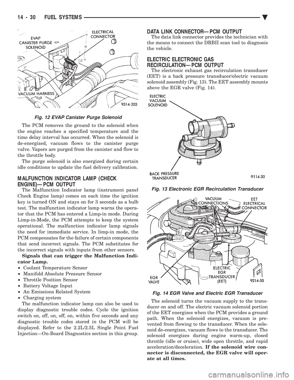
The PCM removes the ground to the solenoid when
the engine reaches a specified temperature and the
time delay interval has occurred. When the solenoid is
de-energized, vacuum flows to the canister purge
valve. Vapors are purged from the canister and flow to
the throttle body. The purge solenoid is also energized during certain
idle conditions to update the fuel delivery calibration.
MALFUNCTION INDICATOR LAMP (CHECK
ENGINE)ÐPCM OUTPUT
The Malfunction Indicator lamp (instrument panel
Check Engine lamp) comes on each time the ignition
key is turned ON and stays on for 3 seconds as a bulb
test. The malfunction indicator lamp warns the opera-
tor that the PCM has entered a Limp-in mode. During
Limp-in-Mode, the PCM attempts to keep the system
operational. The malfunction indicator lamp signals
the need for immediate service. In limp-in mode, the
PCM compensates for the failure of certain components
that send incorrect signals. The PCM substitutes for
the incorrect signals with inputs from other sensors. Signals that can trigger the Malfunction Indi-
cator Lamp.
² Coolant Temperature Sensor
² Manifold Absolute Pressure Sensor
² Throttle Position Sensor
² Battery Voltage Input
² An Emissions Related System
² Charging system
The malfunction indicator lamp can also be used to
display diagnostic trouble codes. Cycle the ignition
switch on, off, on, off, on, within five seconds and any
diagnostic trouble codes stored in the PCM will be
displayed. Refer to the 2.2L/2.5L Single Point Fuel
InjectionÐOn-Board Diagnostics section in this group.
DATA LINK CONNECTORÐPCM OUTPUT
The data link connector provides the technician with
the means to connect the DRBII scan tool to diagnosis
the vehicle.
ELECTRIC ELECTRONIC GAS
RECIRCULATIONÐPCM OUTPUT
The electronic exhaust gas recirculation transducer
(EET) is a back pressure transducer/electric vacuum
solenoid assembly (Fig. 13). The EET assembly mounts
above the EGR valve (Fig. 14).
The solenoid turns the vacuum supply to the trans-
ducer on and off. The electric vacuum solenoid portion
of the EET energizes when the PCM provides a ground
path. When the solenoid energizes, vacuum is pre-
vented from flowing to the transducer. When the sole-
noid de-energizes, vacuum flows to the transducer. The
solenoid energizes during engine warm-up, closed
throttle (idle or cruise), wide open throttle, and rapid
acceleration/deceleration. If the solenoid wire con-
nector is disconnected, the EGR valve will oper-
ate at all times.
Fig. 12 EVAP Canister Purge Solenoid
Fig. 13 Electronic EGR Recirculation Transducer
Fig. 14 EGR Valve and Electric EGR Transducer
14 - 30 FUEL SYSTEMS Ä