1993 CHEVROLET DYNASTY charging
[x] Cancel search: chargingPage 379 of 2438

After 15 seconds, record the loaded voltage reading
and return the load control to the off position. (6) Voltage drop will vary according to battery
temperature at the time of the load test. Battery
temperature can be estimated by the temperature of
exposure over the preceding several hours. If the bat-
tery has been charged, boosted, or loaded a few min-
utes prior to the test, the battery would be slightly
warmer. Refer to Fig. 14 for proper loaded voltage
reading.
(7) If battery passes load test, it is in good condi-
tion and further tests are not necessary. If it fails
load test, it should be replaced.
BATTERY CHARGING
A battery is considered fully charged when it will
meet all the following requirements:
² It has an open circuit voltage charge of at least
12.4 volts (Fig. 9)
² It passes the 15 second load test (Fig. 14)
² The built in test indicator dot is GREEN (Fig. 5)
² The battery cannot be refilled with water. It must
be replaced WARNING: DO NOT CHARGE A BATTERY THAT
HAS EXCESSIVELY LOW ELECTROLYTE LEVEL.
BATTERY MAY SPARK INTERNALLY AND EX-
PLODE. EXPLOSIVE GASES FORM OVER THE BATTERY.
DO NOT SMOKE, USE FLAME, OR CREATE
SPARKS NEAR BATTERY. DO NOT ASSIST BOOST OR CHARGE A FROZEN
BATTERY. BATTERY CASING MAY FRACTURE. BATTERY ACID IS POISON, AND MAY CAUSE SE-
VERE BURNS AND THE BATTERY CONTAIN SUL-
FURIC ACID. AVOID CONTACT WITH SKIN, EYES,
OR CLOTHING. IN THE EVENT OF CONTACT,
FLUSH WITH WATER AND CALL PHYSICIAN IMME-
DIATELY. KEEP OUT OF REACH OF CHILDREN.
CAUTION: Disconnect the battery negative cable
first (Fig. 15) before charging battery to avoid dam-
age to electrical systems. Do not exceed 16.0 volts
while charging battery. Refer to the instructions
supplied with charging equipment
Battery electrolyte will bubble inside the battery
case while being charged properly. If the electrolyte
boils violently, or is discharged from the vent holes
while charging, immediately reduce charging rate or
turn off charger. Evaluate battery condition. Battery
damage may occur if charging is excessive. Some battery chargers are equipped with polarity
sensing devices to protect the charger or battery from
being damaged if improperly connected. If the bat-
tery state of charge is too low for the polarity sensor
to detect, the sensor must be bypassed for charger to
operate. Refer to operating instructions provided
with battery charger being used.
CAUTION: Charge battery until test indicator ap-
pears green. Do not overcharge.
It may be necessary to jiggle the battery or vehicle
to bring the green dot (in the test indicator) into
view. After the battery has been charged to 12.4 volts or
greater, perform a load test to decide cranking capac-
Fig. 13 Load 50 Percent Cold Crank Rating
Fig. 14 Load Test Temperature
Fig. 15 Disconnect Negative Battery Cable
Ä BATTERY/STARTING/CHARGING SYSTEMS DIAGNOSTICS 8A - 7
Page 380 of 2438

ity. Refer to Battery Load Test. If the battery will
endure a load test, return the battery to use. If bat-
tery will not endure a load test, it must be replaced.
Properly clean and inspect battery hold downs, tray,
terminals, cables, posts, and top before completing
service. Also refer to Group 8B, Battery/Starter/Gen-
erator Service.
CHARGING TIME REQUIRED
The time required to charge a battery will vary de-
pending upon the following factors:
² SIZE OF BATTERY
A completely discharged large heavy-duty battery
requires more than twice the recharging time as a
completely discharged small capacity battery (Fig.
16).
² TEMPERATURE: A longer time will be needed to
charge a battery at -18ÉC (0ÉF) than at 27ÉC (80ÉF).
When a fast charger is connected to a cold battery,
current accepted by battery will be very low at first.
In time, the battery will accept a higher rate as bat-
tery warms.
² CHARGER CAPACITY: A charger which, can sup-
ply only five amperes will require a much longer pe-
riod of charging than a charger that can supply 30
amperes or more.
² STATE OF CHARGE: A completely discharged
battery requires more charging time than a partially
charged battery. Electrolyte is nearly pure water in a
completely discharged battery. At first, the charging
current amperage will be low. As water is converted
to sulfuric acid inside the battery, the current amp
rate will rise. Also, the specific gravity of the electro-
lyte will rise, bringing the green dot (Fig. 5) into
view.
WARNING: NEVER EXCEED 20 AMPS WHEN
CHARGING A COLD -1ÉC (30ÉF) BATTERY. PER-
SONAL INJURY MAY RESULT.
CHARGING COMPLETELY DISCHARGED BATTERY
The following procedure should be used to recharge
a completely discharged battery. Unless procedure is
properly followed, a good battery may be needlessly
replaced (Fig. 17).
(1) Measure the voltage at battery posts with a
voltmeter accurate to 1/10 volt (Fig. 18). If below 10
volts, charge current will be low, and it could take
some time before it accepts a current in excess of a
few milliamperes. Such low current may not be de-
tectable on amp meters built into many chargers.
(2) Connect charger leads. Some chargers feature
polarity protection circuitry which, prevents opera-
tion unless charger is connected to battery posts cor-
rectly. A completely discharged battery may not have
enough voltage to activate this circuitry. This may
happen even if the leads are connected properly. (3) Battery chargers vary in the amount of voltage
and current they provide. For the time required for
the battery to accept measurable charger current at
various voltages, refer to Fig. 17. If charge current is
still not measurable after charging period the battery
should be replaced. If charge current is measurable
during charging time, the battery may be good, and
charging should be completed in the normal manner.
Fig. 16 Battery Charging Time
Fig. 17 Charge Rate
Fig. 18 Voltmeter Accurate to 1/10 Volt (Connected)
8A - 8 BATTERY/STARTING/CHARGING SYSTEMS DIAGNOSTICS Ä
Page 381 of 2438

IGNITION OFF DRAW (IOD)
GENERAL INFORMATION
A normal electrical system will draw from 5 to 30
milliamperes from the battery. This is with the ignition
in the OFF position, and all non-ignition controlled cir-
cuits in proper working order. The amount of IOD will
depend on body model and electrical components. A ve-
hicle that has not been operated for an extended period
of approximately 20 days may discharge the battery to
an inadequate level. In this case, the Main Fusible Link
Connector should be disconnected. The Main Fusible
Link connector is located rearward of the battery on the
engine wiring harness (Fig. 19).
If the IOD is over 30 milliamperes, the defect must
be found and corrected before condemning the bat-
tery. Usually, the battery can be charged and re-
turned to service (Fig. 16).
IGNITION OFF DRAW (IOD) TESTS
VEHICLES WITHOUT ELECTRONIC AUTOMATIC TRANSMISSION/LOAD LEVELINGSUSPENSION OR ALARM SYSTEMS
Testing for HIGHER AMPERAGE IOD must be
performed first to prevent damage to most milliamp
meters. A standard 12 volt test light and a milliamp meter
that is equipped with two leads will be used for the
following tests. The milliamp meter should be able to
handle up to two amps.
(1) Verify that all electrical accessories are OFF.
Turn off all lights, close trunk lid, close glove box door,
turn off sun visor vanity lights, close all doors and re- move ignition key. Allow the Illuminated Entry System
if equipped to time out in approximately 30 seconds.
(2) Verify the engine compartment lamp bulb is
working by opening/closing hood. Remove the lamp. (3) Disconnect negative battery cable (Fig. 15).
(4) Connect a typical 12 volt test light between the
negative cable clamp and the negative battery post (Fig.
19). The test light may be brightly lit for up to three
minutes or may not be lit at all. This depending on the
body model or electronic components on the vehicle. (a) The term brightly used throughout the follow-
ing tests. This implies the brightness of the test light
will be the same as if it were connected across the
battery posts. This would be with a fully charged bat-
tery.
(b) The test light or the milliamp meter MUST
be positively connected to the battery post and the
battery cable during all IOD testing. (c) Do not allow the test light or the milliamp
meter to become disconnected during any of the
IOD tests. If this happens, the electronic timer
functions will be started and all IOD tests must be
repeated from the beginning. Clamp the test light
at both ends to prevent accidental disconnection.
(d) After three minutes time has elapsed, the test
light should turn OFF or be dimly lit depending on
the electronic components on the vehicle. If the test
light remains BRIGHTLY lit, do not disconnect test
light. Disconnect each fuse or circuit breaker until
test light is either OFF or DIMLY lit. Refer to the
Front Wheel Drive Car Wiring Diagrams Service
Manual. This will eliminate higher amperage IOD. It
is now safe to install the milliamp meter without
damage to the meter to check for low amperage IOD.
(e) Possible sources of high IOD are usually ve-
hicle lamps trunk lamp, glove compartment, lug-
gage compartment, etc.. (f) If test light is still brightly lit after discon-
necting each fuse and circuit breaker, disconnect
the wiring harness from the generator. Refer to
Generator Testing. Do not disconnect test light.
CAUTION: This last test has higher amperage IOD and
must be performed before going on with low amper-
age IOD tests. The higher amperage IOD must be elim-
inated before hooking up milliamp meter to check for
low amperage IOD. If higher amperage IOD has not
been eliminated, milliamp meter may be damaged.
Most milliamp meters will not handle over one or two
amps. Do not hook up meter if test light is glowing
brightly. Refer to maximum amperage specifications
and instructions supplied with milliamp meter.
After higher amperage IOD has been corrected, low
amperage IOD may be checked. The MAXIMUM IOD=
30 MILLIAMPERES.
Fig. 19 IOD Test
Ä BATTERY/STARTING/CHARGING SYSTEMS DIAGNOSTICS 8A - 9
Page 382 of 2438
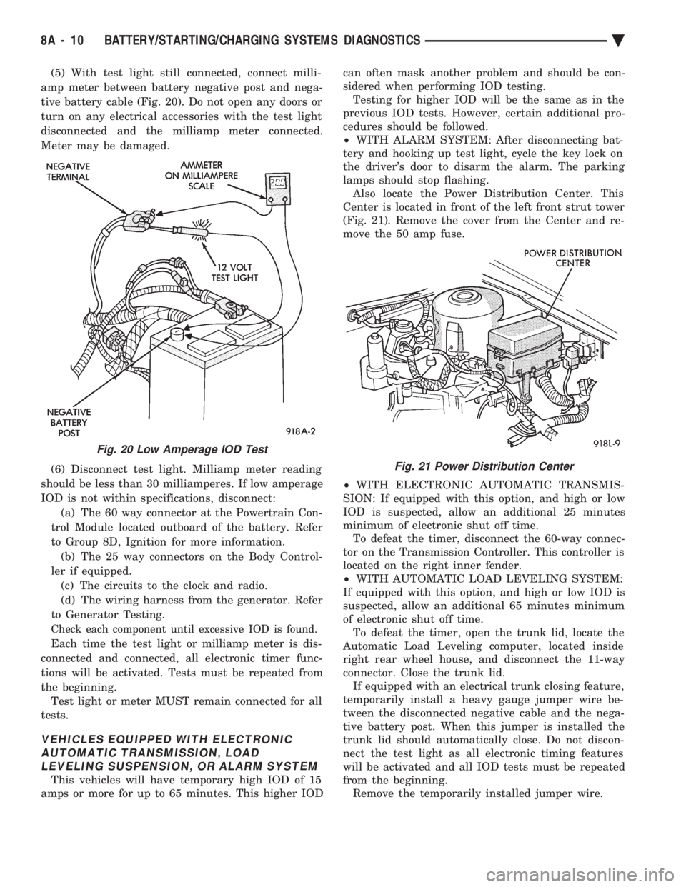
(5) With test light still connected, connect milli-
amp meter between battery negative post and nega-
tive battery cable (Fig. 20). Do not open any doors or
turn on any electrical accessories with the test light
disconnected and the milliamp meter connected.
Meter may be damaged.
(6) Disconnect test light. Milliamp meter reading
should be less than 30 milliamperes. If low amperage
IOD is not within specifications, disconnect: (a) The 60 way connector at the Powertrain Con-
trol Module located outboard of the battery. Refer
to Group 8D, Ignition for more information. (b) The 25 way connectors on the Body Control-
ler if equipped. (c) The circuits to the clock and radio.
(d) The wiring harness from the generator. Refer
to Generator Testing.
Check each component until excessive IOD is found.
Each time the test light or milliamp meter is dis-
connected and connected, all electronic timer func-
tions will be activated. Tests must be repeated from
the beginning. Test light or meter MUST remain connected for all
tests.
VEHICLES EQUIPPED WITH ELECTRONIC AUTOMATIC TRANSMISSION, LOADLEVELING SUSPENSION, OR ALARM SYSTEM
This vehicles will have temporary high IOD of 15
amps or more for up to 65 minutes. This higher IOD can often mask another problem and should be con-
sidered when performing IOD testing. Testing for higher IOD will be the same as in the
previous IOD tests. However, certain additional pro-
cedures should be followed.
² WITH ALARM SYSTEM: After disconnecting bat-
tery and hooking up test light, cycle the key lock on
the driver's door to disarm the alarm. The parking
lamps should stop flashing. Also locate the Power Distribution Center. This
Center is located in front of the left front strut tower
(Fig. 21). Remove the cover from the Center and re-
move the 50 amp fuse.
² WITH ELECTRONIC AUTOMATIC TRANSMIS-
SION: If equipped with this option, and high or low
IOD is suspected, allow an additional 25 minutes
minimum of electronic shut off time. To defeat the timer, disconnect the 60-way connec-
tor on the Transmission Controller. This controller is
located on the right inner fender.
² WITH AUTOMATIC LOAD LEVELING SYSTEM:
If equipped with this option, and high or low IOD is
suspected, allow an additional 65 minutes minimum
of electronic shut off time. To defeat the timer, open the trunk lid, locate the
Automatic Load Leveling computer, located inside
right rear wheel house, and disconnect the 11-way
connector. Close the trunk lid. If equipped with an electrical trunk closing feature,
temporarily install a heavy gauge jumper wire be-
tween the disconnected negative cable and the nega-
tive battery post. When this jumper is installed the
trunk lid should automatically close. Do not discon-
nect the test light as all electronic timing features
will be activated and all IOD tests must be repeated
from the beginning. Remove the temporarily installed jumper wire.
Fig. 20 Low Amperage IOD Test
Fig. 21 Power Distribution Center
8A - 10 BATTERY/STARTING/CHARGING SYSTEMS DIAGNOSTICS Ä
Page 383 of 2438
STARTER TEST PROCEDURES ON VEHICLE INDEX
page page
Diagnostic Preparation ..................... 11
General Information ....................... 11 Starter Control Circuit Tests
................ 15
Starter Feed Circuit Tests .................. 11
GENERAL INFORMATION
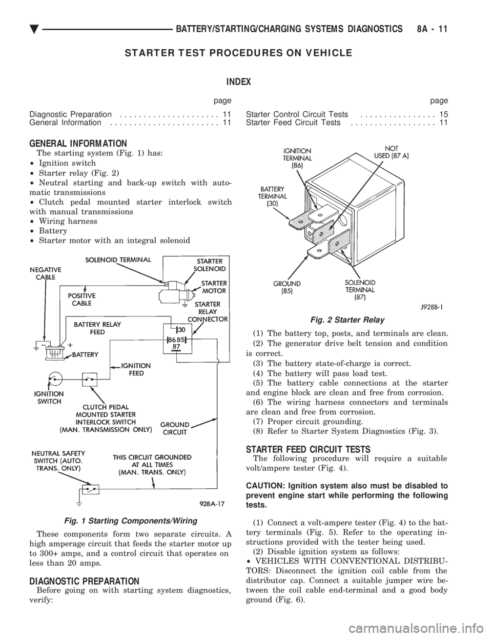
The starting system (Fig. 1) has:
² Ignition switch
² Starter relay (Fig. 2)
² Neutral starting and back-up switch with auto-
matic transmissions
² Clutch pedal mounted starter interlock switch
with manual transmissions
² Wiring harness
² Battery
² Starter motor with an integral solenoid
These components form two separate circuits. A
high amperage circuit that feeds the starter motor up
to 300+ amps, and a control circuit that operates on
less than 20 amps.
DIAGNOSTIC PREPARATION
Before going on with starting system diagnostics,
verify: (1) The battery top, posts, and terminals are clean.
(2) The generator drive belt tension and condition
is correct. (3) The battery state-of-charge is correct.
(4) The battery will pass load test.
(5) The battery cable connections at the starter
and engine block are clean and free from corrosion. (6) The wiring harness connectors and terminals
are clean and free from corrosion. (7) Proper circuit grounding.
(8) Refer to Starter System Diagnostics (Fig. 3).
STARTER FEED CIRCUIT TESTS
The following procedure will require a suitable
volt/ampere tester (Fig. 4).
CAUTION: Ignition system also must be disabled to
prevent engine start while performing the following
tests.
(1) Connect a volt-ampere tester (Fig. 4) to the bat-
tery terminals (Fig. 5). Refer to the operating in-
structions provided with the tester being used. (2) Disable ignition system as follows:
² VEHICLES WITH CONVENTIONAL DISTRIBU-
TORS: Disconnect the ignition coil cable from the
distributor cap. Connect a suitable jumper wire be-
tween the coil cable end-terminal and a good body
ground (Fig. 6).
Fig. 1 Starting Components/Wiring
Fig. 2 Starter Relay
Ä BATTERY/STARTING/CHARGING SYSTEMS DIAGNOSTICS 8A - 11
Page 384 of 2438

Fig. 3 Starter System Diagnostics
8A - 12 BATTERY/STARTING/CHARGING SYSTEMS DIAGNOSTICS Ä
Page 385 of 2438
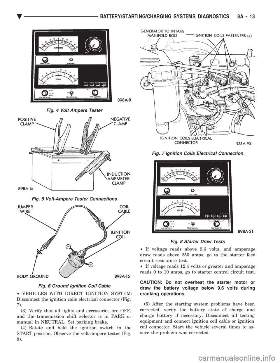
² VEHICLES WITH DIRECT IGNITION SYSTEM:
Disconnect the ignition coils electrical connector (Fig.
7). (3) Verify that all lights and accessories are OFF,
and the transmission shift selector is in PARK or
manual in NEUTRAL. Set parking brake. (4) Rotate and hold the ignition switch in the
START position. Observe the volt-ampere tester (Fig.
8). ²
If voltage reads above 9.6 volts, and amperage
draw reads above 250 amps, go to the starter feed
circuit resistance test.
² If voltage reads 12.4 volts or greater and amperage
reads 0 to 10 amps, go to starter control circuit test.
CAUTION: Do not overheat the starter motor or
draw the battery voltage below 9.6 volts during
cranking operations.
(5) After the starting system problems have been
corrected, verify the battery state of charge and
charge battery if necessary. Disconnect all testing
equipment and connect ignition coil cable or ignition
coil connector. Start the vehicle several times to as-
sure the problem was corrected.
Fig. 4 Volt Ampere Tester
Fig. 5 Volt-Ampere Tester Connections
Fig. 6 Ground Ignition Coil Cable
Fig. 7 Ignition Coils Electrical Connection
Fig. 8 Starter Draw Tests
Ä BATTERY/STARTING/CHARGING SYSTEMS DIAGNOSTICS 8A - 13
Page 386 of 2438
STARTER FEED CIRCUIT RESISTANCE TEST
Before going on with this operation, review Diag-
nostic Preparation and Starter Feed Circuit Tests.
The following operation will require a voltmeter, ac-
curate to 1/10 of a volt.
CAUTION: Ignition system also must be disabled to
prevent engine start while performing the following
tests.
(1) Disable ignition system as follows:
² VEHICLES WITH CONVENTIONAL DISTRIBU-
TORS: Disconnect the ignition coil cable from the
distributor cap. Connect a suitable jumper wire be-
tween the coil cable end-terminal and a good body
ground (Fig. 6).
² VEHICLES WITH DIRECT IGNITION SYSTEM:
Disconnect the ignition coils electrical connector (Fig.
7). (2) With all wiring harnesses and components
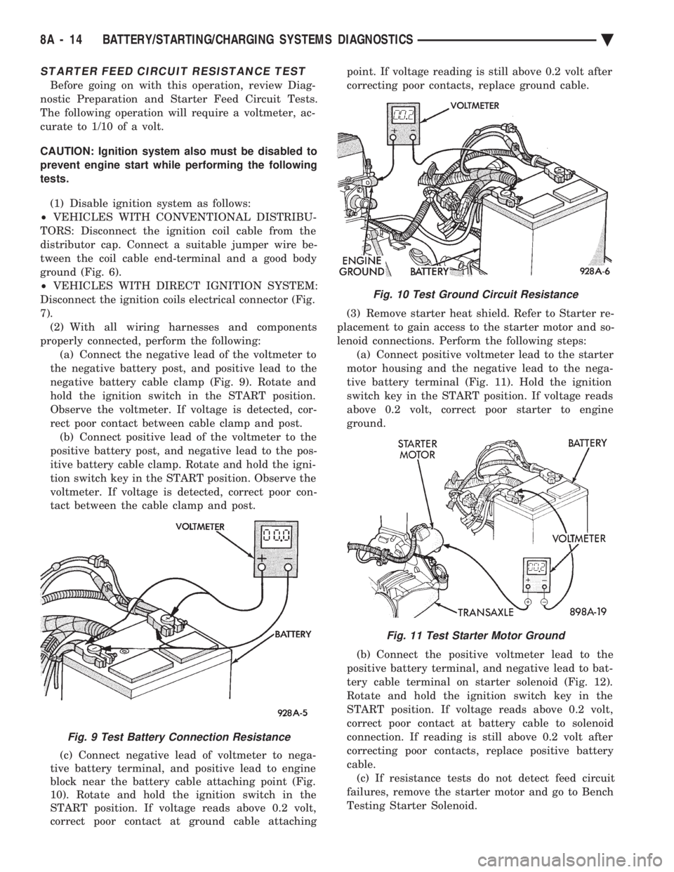
properly connected, perform the following: (a) Connect the negative lead of the voltmeter to
the negative battery post, and positive lead to the
negative battery cable clamp (Fig. 9). Rotate and
hold the ignition switch in the START position.
Observe the voltmeter. If voltage is detected, cor-
rect poor contact between cable clamp and post. (b) Connect positive lead of the voltmeter to the
positive battery post, and negative lead to the pos-
itive battery cable clamp. Rotate and hold the igni-
tion switch key in the START position. Observe the
voltmeter. If voltage is detected, correct poor con-
tact between the cable clamp and post.
(c) Connect negative lead of voltmeter to nega-
tive battery terminal, and positive lead to engine
block near the battery cable attaching point (Fig.
10). Rotate and hold the ignition switch in the
START position. If voltage reads above 0.2 volt,
correct poor contact at ground cable attaching point. If voltage reading is still above 0.2 volt after
correcting poor contacts, replace ground cable.
(3) Remove starter heat shield. Refer to Starter re-
placement to gain access to the starter motor and so-
lenoid connections. Perform the following steps: (a) Connect positive voltmeter lead to the starter
motor housing and the negative lead to the nega-
tive battery terminal (Fig. 11). Hold the ignition
switch key in the START position. If voltage reads
above 0.2 volt, correct poor starter to engine
ground.
(b) Connect the positive voltmeter lead to the
positive battery terminal, and negative lead to bat-
tery cable terminal on starter solenoid (Fig. 12).
Rotate and hold the ignition switch key in the
START position. If voltage reads above 0.2 volt,
correct poor contact at battery cable to solenoid
connection. If reading is still above 0.2 volt after
correcting poor contacts, replace positive battery
cable. (c) If resistance tests do not detect feed circuit
failures, remove the starter motor and go to Bench
Testing Starter Solenoid.
Fig. 9 Test Battery Connection Resistance
Fig. 10 Test Ground Circuit Resistance
Fig. 11 Test Starter Motor Ground
8A - 14 BATTERY/STARTING/CHARGING SYSTEMS DIAGNOSTICS Ä