1993 CHEVROLET DYNASTY brake
[x] Cancel search: brakePage 2308 of 2438
VACUUM CONTROL SYSTEM DIAGNOSIS
GENERAL INFORMATION
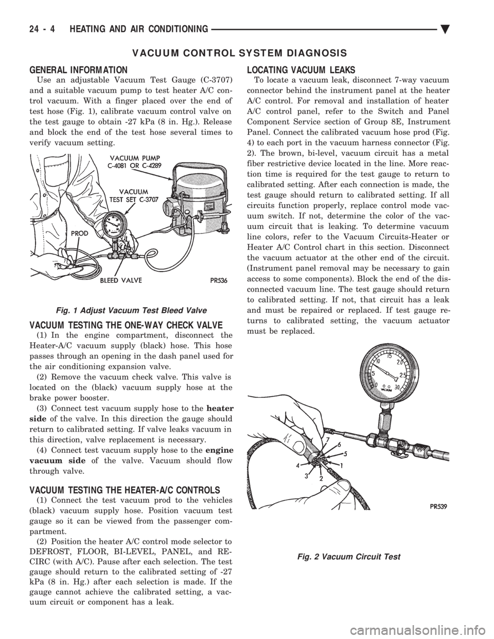
Use an adjustable Vacuum Test Gauge (C-3707)
and a suitable vacuum pump to test heater A/C con-
trol vacuum. With a finger placed over the end of
test hose (Fig. 1), calibrate vacuum control valve on
the test gauge to obtain -27 kPa (8 in. Hg.). Release
and block the end of the test hose several times to
verify vacuum setting.
VACUUM TESTING THE ONE-WAY CHECK VALVE
(1) In the engine compartment, disconnect the
Heater-A/C vacuum supply (black) hose. This hose
passes through an opening in the dash panel used for
the air conditioning expansion valve. (2) Remove the vacuum check valve. This valve is
located on the (black) vacuum supply hose at the
brake power booster. (3) Connect test vacuum supply hose to the heater
side of the valve. In this direction the gauge should
return to calibrated setting. If valve leaks vacuum in
this direction, valve replacement is necessary. (4) Connect test vacuum supply hose to the engine
vacuum side of the valve. Vacuum should flow
through valve.
VACUUM TESTING THE HEATER-A/C CONTROLS
(1) Connect the test vacuum prod to the vehicles
(black) vacuum supply hose. Position vacuum test
gauge so it can be viewed from the passenger com-
partment. (2) Position the heater A/C control mode selector to
DEFROST, FLOOR, BI-LEVEL, PANEL, and RE-
CIRC (with A/C). Pause after each selection. The test
gauge should return to the calibrated setting of -27
kPa (8 in. Hg.) after each selection is made. If the
gauge cannot achieve the calibrated setting, a vac-
uum circuit or component has a leak.
LOCATING VACUUM LEAKS
To locate a vacuum leak, disconnect 7-way vacuum
connector behind the instrument panel at the heater
A/C control. For removal and installation of heater
A/C control panel, refer to the Switch and Panel
Component Service section of Group 8E, Instrument
Panel. Connect the calibrated vacuum hose prod (Fig.
4) to each port in the vacuum harness connector (Fig.
2). The brown, bi-level, vacuum circuit has a metal
fiber restrictive device located in the line. More reac-
tion time is required for the test gauge to return to
calibrated setting. After each connection is made, the
test gauge should return to calibrated setting. If all
circuits function properly, replace control mode vac-
uum switch. If not, determine the color of the vac-
uum circuit that is leaking. To determine vacuum
line colors, refer to the Vacuum Circuits-Heater or
Heater A/C Control chart in this section. Disconnect
the vacuum actuator at the other end of the circuit.
(Instrument panel removal may be necessary to gain
access to some components). Block the end of the dis-
connected vacuum line. The test gauge should return
to calibrated setting. If not, that circuit has a leak
and must be repaired or replaced. If test gauge re-
turns to calibrated setting, the vacuum actuator
must be replaced.
Fig. 1 Adjust Vacuum Test Bleed Valve
Fig. 2 Vacuum Circuit Test
24 - 4 HEATING AND AIR CONDITIONING Ä
Page 2325 of 2438
(5) Evacuate and charge the refrigerant system. If
oil loss of 3 ml (1 oz) or greater is suspected, refer to
Oil Level in the Refrigerant Service Procedures sec-
tion.
COMPRESSOR HIGH PRESSURE CUT-OUT SWITCH
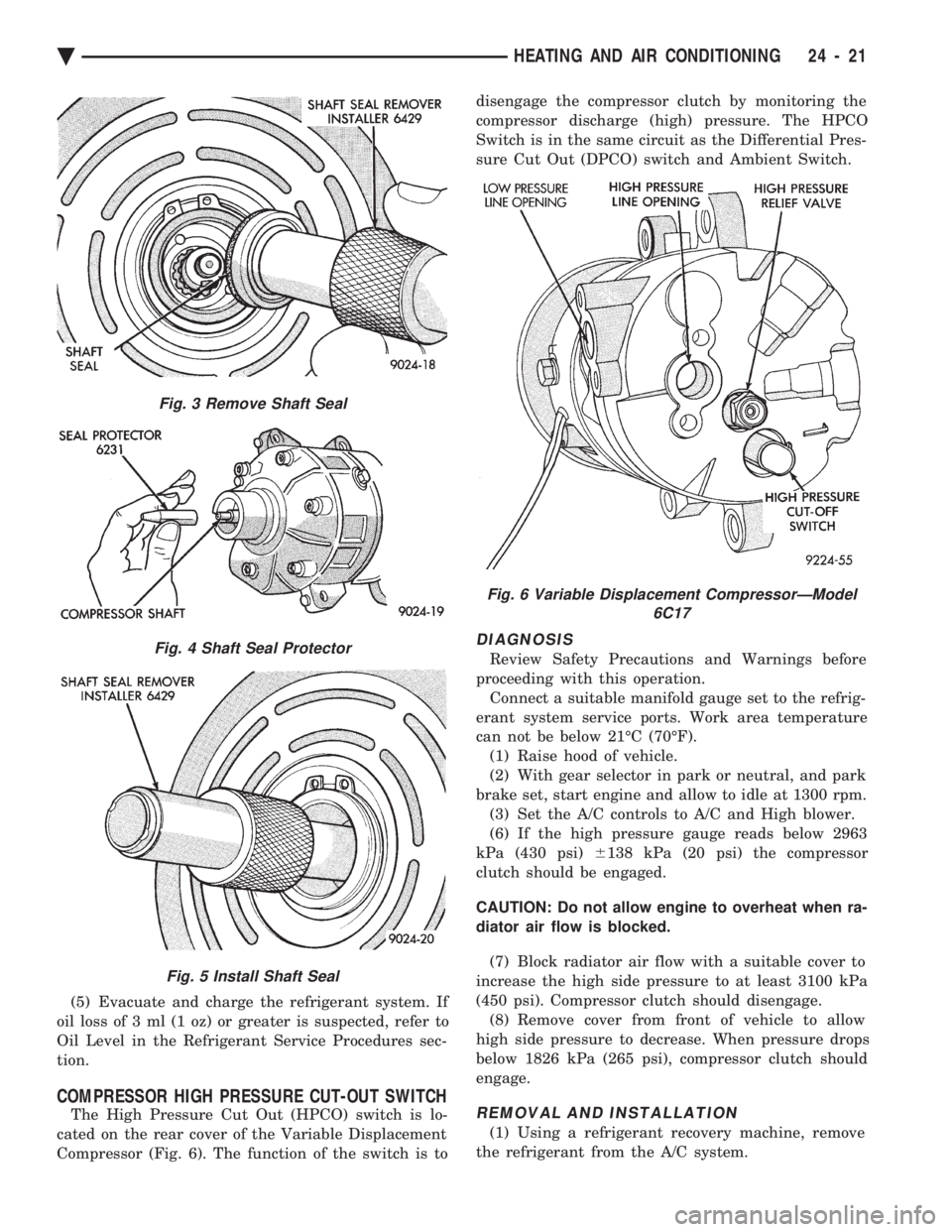
The High Pressure Cut Out (HPCO) switch is lo-
cated on the rear cover of the Variable Displacement
Compressor (Fig. 6). The function of the switch is to disengage the compressor clutch by monitoring the
compressor discharge (high) pressure. The HPCO
Switch is in the same circuit as the Differential Pres-
sure Cut Out (DPCO) switch and Ambient Switch.
DIAGNOSIS
Review Safety Precautions and Warnings before
proceeding with this operation. Connect a suitable manifold gauge set to the refrig-
erant system service ports. Work area temperature
can not be below 21ÉC (70ÉF). (1) Raise hood of vehicle.
(2) With gear selector in park or neutral, and park
brake set, start engine and allow to idle at 1300 rpm. (3) Set the A/C controls to A/C and High blower.
(6) If the high pressure gauge reads below 2963
kPa (430 psi) 6138 kPa (20 psi) the compressor
clutch should be engaged.
CAUTION: Do not allow engine to overheat when ra-
diator air flow is blocked.
(7) Block radiator air flow with a suitable cover to
increase the high side pressure to at least 3100 kPa
(450 psi). Compressor clutch should disengage. (8) Remove cover from front of vehicle to allow
high side pressure to decrease. When pressure drops
below 1826 kPa (265 psi), compressor clutch should
engage.
REMOVAL AND INSTALLATION
(1) Using a refrigerant recovery machine, remove
the refrigerant from the A/C system.
Fig. 3 Remove Shaft Seal
Fig. 4 Shaft Seal Protector
Fig. 5 Install Shaft Seal
Fig. 6 Variable Displacement CompressorÐModel 6C17
Ä HEATING AND AIR CONDITIONING 24 - 21
Page 2352 of 2438
WARNING: AVOID RADIATOR/CONDENSER FAN
BLADES WHEN WORKING IN THE RADIATOR
AREA. FAN IS CONTROLLED BY TEMPERATURE
AND CAN START ANY TIME IGNITION IS ON. PER-
SONAL INJURY CAN RESULT.
(1) Disconnect fan control switch wire connector.
(2) Using a suitable jumper wire, jump across ter-
minals in wire connector. (3) Connect a suitable continuity tester across fan
control switch terminals. (4) Start engine and set idle at 1300 rpm. The ra-
diator fan should run constantly. (5) Set the A/C controls to A/C and high blower.
(6) If the high pressure gauge reads below 1102
kPa (160 psi) there should be no continuity across
the switch terminals.
CAUTION: Do not allow engine to overheat when ra-
diator air flow is blocked.
(7) Block radiator air flow with a suitable cover to
increase the high side pressure to at least 1585 kPa
(230 psi). Electrical continuity should be detected
across the fan control switch terminals. (8) Remove cover from front of vehicle to allow
high side pressure to decrease. When pressure drops
below 1102 kPa (160 psi), continuity should cease. If fan control switch is defective, replace it.
REMOVAL AND INSTALLATION
CAUTION: Refrigerant removal is not necessary
when removing the Condenser Fan Control Switch.
However, a small amount of refrigerant will vent
from the switch port. Review the refrigerant han-
dling section of Safety Precautions and Warnings in
the General Information section of this Group.
(1) Disconnect wire connector from condenser fan
control switch. (2) Loosen and quickly rotate the switch counter-
clockwise and separate from the high pressure line
switch port. To install, reverse the preceding operation.
DIFFERENTIAL PRESSURE CUT-OUT SWITCH
DIAGNOSIS
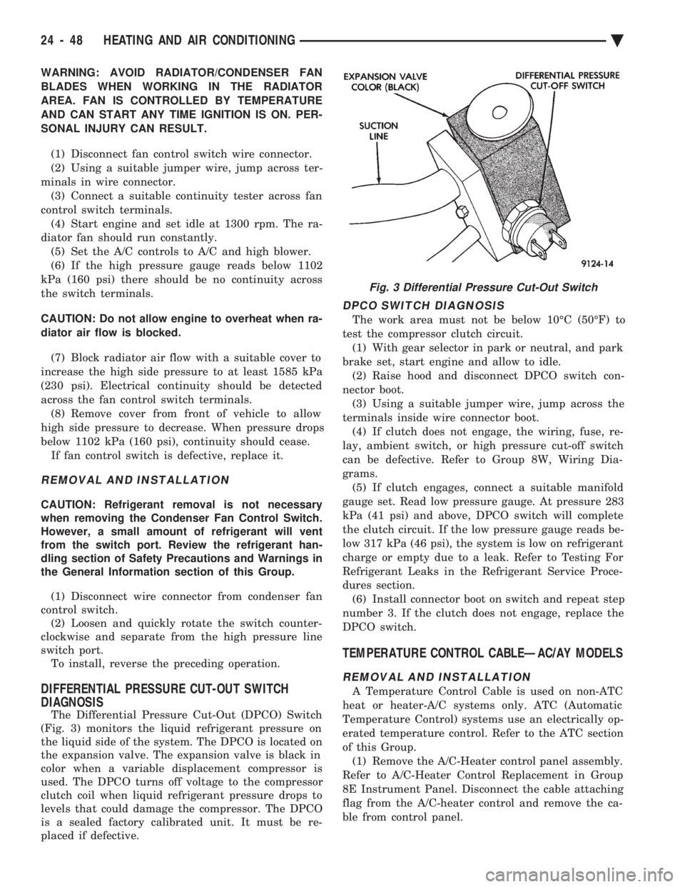
The Differential Pressure Cut-Out (DPCO) Switch
(Fig. 3) monitors the liquid refrigerant pressure on
the liquid side of the system. The DPCO is located on
the expansion valve. The expansion valve is black in
color when a variable displacement compressor is
used. The DPCO turns off voltage to the compressor
clutch coil when liquid refrigerant pressure drops to
levels that could damage the compressor. The DPCO
is a sealed factory calibrated unit. It must be re-
placed if defective.
DPCO SWITCH DIAGNOSIS
The work area must not be below 10ÉC (50ÉF) to
test the compressor clutch circuit. (1) With gear selector in park or neutral, and park
brake set, start engine and allow to idle. (2) Raise hood and disconnect DPCO switch con-
nector boot. (3) Using a suitable jumper wire, jump across the
terminals inside wire connector boot. (4) If clutch does not engage, the wiring, fuse, re-
lay, ambient switch, or high pressure cut-off switch
can be defective. Refer to Group 8W, Wiring Dia-
grams. (5) If clutch engages, connect a suitable manifold
gauge set. Read low pressure gauge. At pressure 283
kPa (41 psi) and above, DPCO switch will complete
the clutch circuit. If the low pressure gauge reads be-
low 317 kPa (46 psi), the system is low on refrigerant
charge or empty due to a leak. Refer to Testing For
Refrigerant Leaks in the Refrigerant Service Proce-
dures section. (6) Install connector boot on switch and repeat step
number 3. If the clutch does not engage, replace the
DPCO switch.
TEMPERATURE CONTROL CABLEÐAC/AY MODELS
REMOVAL AND INSTALLATION
A Temperature Control Cable is used on non-ATC
heat or heater-A/C systems only. ATC (Automatic
Temperature Control) systems use an electrically op-
erated temperature control. Refer to the ATC section
of this Group. (1) Remove the A/C-Heater control panel assembly.
Refer to A/C-Heater Control Replacement in Group
8E Instrument Panel. Disconnect the cable attaching
flag from the A/C-heater control and remove the ca-
ble from control panel.
Fig. 3 Differential Pressure Cut-Out Switch
24 - 48 HEATING AND AIR CONDITIONING Ä
Page 2358 of 2438
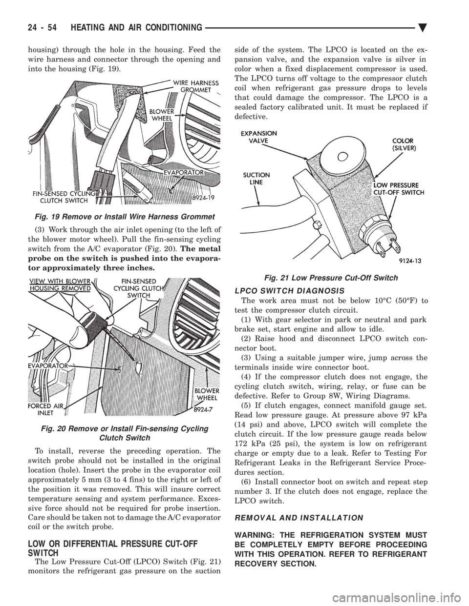
housing) through the hole in the housing. Feed the
wire harness and connector through the opening and
into the housing (Fig. 19). (3) Work through the air inlet opening (to the left of
the blower motor wheel). Pull the fin-sensing cycling
switch from the A/C evaporator (Fig. 20). The metal
probe on the switch is pushed into the evapora-
tor approximately three inches.
To install, reverse the preceding operation. The
switch probe should not be installed in the original
location (hole). Insert the probe in the evaporator coil
approximately 5 mm (3 to 4 fins) to the right or left of
the position it was removed. This will insure correct
temperature sensing and system performance. Exces-
sive force should not be required for probe insertion.
Care should be taken not to damage the A/C evaporator
coil or the switch probe.
LOW OR DIFFERENTIAL PRESSURE CUT-OFF
SWITCH
The Low Pressure Cut-Off (LPCO) Switch (Fig. 21)
monitors the refrigerant gas pressure on the suction side of the system. The LPCO is located on the ex-
pansion valve, and the expansion valve is silver in
color when a fixed displacement compressor is used.
The LPCO turns off voltage to the compressor clutch
coil when refrigerant gas pressure drops to levels
that could damage the compressor. The LPCO is a
sealed factory calibrated unit. It must be replaced if
defective.
LPCO SWITCH DIAGNOSIS
The work area must not be below 10ÉC (50ÉF) to
test the compressor clutch circuit. (1) With gear selector in park or neutral and park
brake set, start engine and allow to idle. (2) Raise hood and disconnect LPCO switch con-
nector boot. (3) Using a suitable jumper wire, jump across the
terminals inside wire connector boot. (4) If the compressor clutch does not engage, the
cycling clutch switch, wiring, relay, or fuse can be
defective. Refer to Group 8W, Wiring Diagrams. (5) If clutch engages, connect manifold gauge set.
Read low pressure gauge. At pressure above 97 kPa
(14 psi) and above, LPCO switch will complete the
clutch circuit. If the low pressure gauge reads below
172 kPa (25 psi), the system is low on refrigerant
charge or empty due to a leak. Refer to Testing For
Refrigerant Leaks in the Refrigerant Service Proce-
dures section. (6) Install connector boot on switch and repeat step
number 3. If the clutch does not engage, replace the
LPCO switch.
REMOVAL AND INSTALLATION
WARNING: THE REFRIGERATION SYSTEM MUST
BE COMPLETELY EMPTY BEFORE PROCEEDING
WITH THIS OPERATION. REFER TO REFRIGERANT
RECOVERY SECTION.
Fig. 21 Low Pressure Cut-Off Switch
Fig. 19 Remove or Install Wire Harness Grommet
Fig. 20 Remove or Install Fin-sensing Cycling Clutch Switch
24 - 54 HEATING AND AIR CONDITIONING Ä
Page 2366 of 2438
AA BODY PROCEDURE
WARNING: IF EQUIPPED WITH A/C, THE REFRIG-
ERATION SYSTEM MUST BE COMPLETELY EMPTY
BEFORE PROCEEDING WITH THIS OPERATION. Refer to Group 8E and Group 23 for component re-
moval and installation when performing this opera-
tion. (1) Perform steps 1 through 7 of Blower Motor re-
moval and installation. (2) Remove relay panel above glove compartment
opening. (3) Disconnect the A/C vacuum line connector and
radio noise capacitor connectors. (4) Remove left windshield pillar trim cover.
(5) Remove left lower side cowl trim cover.
(6) Remove hood release handle mechanism attach-
ing screws. (7) Remove steering column trim covers.
(8) Disconnect parking brake release mechanism
connecting rod. Gain access through fuse panel open-
ing. (9) Remove lower left instrument panel silencer.
(10) Remove lower left instrument panel reinforce-
ment. (11) Remove instrument panel center (radio) bezel.
(12) Remove forward floor console.
(13) Remove the radio.
(14) Remove the heater-A/C control.
(15) Remove cigar lighter.
(16) Remove message center/trip computer, if
equipped. (17) Disconnect side window demister tubes from
top of heat A/C unit. (18) Remove steering column upper attaching bolts
and allow the steering wheel to rest on the driver
seat cushion. (19) Remove upper instrument panel (defroster
outlet) cover. (20) Remove upper instrument panel attaching
screws from below the windshield opening. (21) Loosen (do not remove) the left lower cowl in-
strument panel attaching screw. (22) Remove the right lower cowl instrument panel
attaching screw.
CAUTION: Protect the passenger seat cover from
soiling or damage using a suitable cover.
(23) Carefully pull the right side of the instrument
panel away from the vehicle. Allow the instrument
panel to rest on the passenger seat cushion.
CAUTION: Before proceeding with the next opera-
tion, review the Safety Precautions and Warnings at
the front of this Group. (24) From the engine compartment, drain the cool-
ing system and disconnect the heater hoses from the
heater core nipples. Plug the nipples to avoid spilling
coolant inside the vehicle. (25) Disconnect the refrigerant lines from the ex-
pansion-valve at the dash panel on the right side of
the vehicle. Seal the refrigerant lines to prevent con-
tamination. (26) Remove the expansion valve from the evapo-
rator plate. Seal the valve to avoid contamination. (27) Remove the condensate drain tube.
(28) Remove heater-A/C unit to dash panel attach-
ing nuts. (29) From inside the vehicle, pull rearward on the
heater-A/C unit to clear the dash panel silencer and
remove the unit from the vehicle. To install, reverse the preceding operation. Refill
cooling system and test for leaks. Evacuate and
charge the refrigerant system and test overall perfor-
mance.
AG, AJ BODY PROCEDURE
WARNING: IF EQUIPPED WITH A/C, THE REFRIG-
ERATION SYSTEM MUST BE COMPLETELY EMPTY
BEFORE PROCEEDING WITH THIS OPERATION.
(1) Disconnect the battery negative cable.
(2) Drain the coolant from cooling system. Refer to
Group 7, Cooling System. (3) Remove the air conditioner expansion valve (if
equipped). (4) Disconnect the heater hoses from heater core.
Then plug or cap the tubes on heater core. This will
prevent spilling coolant into the interior of vehicle
during unit removal. (5) Remove the condensate drain tube.
(6) Disconnect the A/C-heater vacuum supply line
from vacuum supply nipple (in the engine compart-
ment). (7) Remove the four A/C-heater assembly-to-dash
panel attaching nuts. (8) Remove the passenger side front seat. Refer to
Group 23, Body. (9) Remove the kick panel/sill cover at right door
opening. (10) Remove the body computer (Fig. 6) located at
the lower right section of the right front door pillar. (11) Remove the glove box assembly. Refer to
Group 8E, Instrument Panel. (12) Remove the carpeted panels from both sides of
the console. (13) Un-clip the radio antenna cable from the
metal support (Fig. 6) located behind and below the
glove box opening. (14) Instrument panel removal is not necessary to
remove the A/C-heater assembly from the vehicle.
24 - 62 HEATING AND AIR CONDITIONING Ä
Page 2403 of 2438
POSITIVE CRANKCASE VENTILATION (PCV)
SYSTEMS
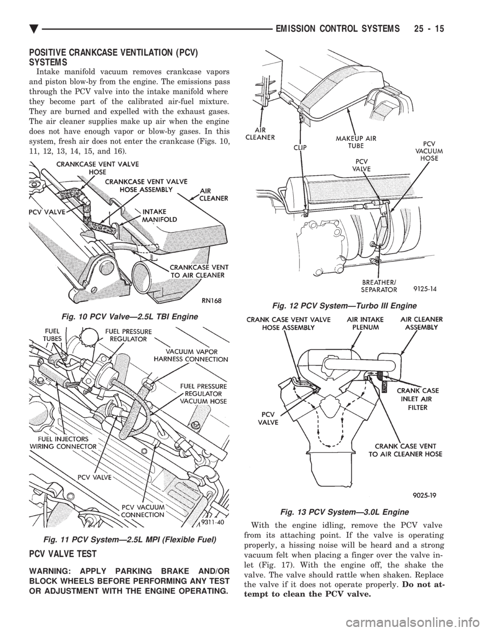
Intake manifold vacuum removes crankcase vapors
and piston blow-by from the engine. The emissions pass
through the PCV valve into the intake manifold where
they become part of the calibrated air-fuel mixture.
They are burned and expelled with the exhaust gases.
The air cleaner supplies make up air when the engine
does not have enough vapor or blow-by gases. In this
system, fresh air does not enter the crankcase (Figs. 10,
11, 12, 13, 14, 15, and 16).
PCV VALVE TEST
WARNING: APPLY PARKING BRAKE AND/OR
BLOCK WHEELS BEFORE PERFORMING ANY TEST
OR ADJUSTMENT WITH THE ENGINE OPERATING. With the engine idling, remove the PCV valve
from its attaching point. If the valve is operating
properly, a hissing noise will be heard and a strong
vacuum felt when placing a finger over the valve in-
let (Fig. 17). With the engine off, the shake the
valve. The valve should rattle when shaken. Replace
the valve if it does not operate properly. Do not at-
tempt to clean the PCV valve.
Fig. 10 PCV ValveÐ2.5L TBI Engine
Fig. 11 PCV SystemÐ2.5L MPI (Flexible Fuel)
Fig. 12 PCV SystemÐTurbo III Engine
Fig. 13 PCV SystemÐ3.0L Engine
Ä EMISSION CONTROL SYSTEMS 25 - 15
Page 2409 of 2438
These systems do not allow EGR at idle. The 2.2L/
2.5L EGR systems operate at all temperatures. The
3.0L, 3.3L and 3.8L EGR systems do not operate
when coolant temperature is below 4.5ÉC (40É)F at
start-up. These systems activate when coolant tem-
perature reaches 77ÉC (170ÉF).
EGR SYSTEM ON-BOARD DIAGNOSTICS
The powertrain control module (PCM) performs an
on-board diagnostic check of the EGR system on all
California vehicles with EGR systems. The diagnos-
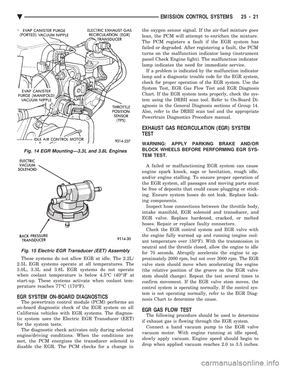
tic system uses the Electric EGR Transducer (EET)
for the system tests. The diagnostic check activates only during selected
engine/driving conditions. When the conditions are
met, the PCM energizes the transducer solenoid to
disable the EGR. The PCM checks for a change in the oxygen sensor signal. If the air-fuel mixture goes
lean, the PCM will attempt to enrichen the mixture.
The PCM registers a fault if the EGR system has
failed or degraded. After registering a fault, the PCM
turns on the malfunction indicator lamp (instrument
panel Check Engine light). The malfunction indicator
lamp indicates the need for immediate service.
If a problem is indicated by the malfunction indicator
lamp and a diagnostic trouble code for the EGR system,
check for proper operation of the EGR system. Use the
System Test, EGR Gas Flow Test and EGR Diagnosis
Chart. If the EGR system tests properly, check the sys-
tem using the DRBII scan tool. Refer to On-Board Di-
agnosis in the General Diagnosis sections of Group 14.
Also, refer to the DRBII scan tool and the appropriate
Powertrain Diagnostics Procedure manual.
EXHAUST GAS RECIRCULATION (EGR) SYSTEM
TEST
WARNING: APPLY PARKING BRAKE AND/OR
BLOCK WHEELS BEFORE PERFORMING EGR SYS-
TEM TEST.
A failed or malfunctioning EGR system can cause
engine spark knock, sags or hesitation, rough idle,
and/or engine stalling. To ensure proper operation of
the EGR system, all passages and moving parts must
be free of deposits that could cause plugging or stick-
ing. Ensure system hoses do not leak. Replace leak-
ing components. Inspect hose connections between the throttle body,
intake manifold, EGR solenoid and transducer, and
EGR valve. Replace hardened, cracked, or melted
hoses. Repair or replace faulty connectors.
Check the EGR control system and EGR valve with
the engine fully warmed up and running (engine cool-
ant temperature over 150ÉF). With the transmission in
neutral and the throttle closed, allow the engine to idle
for 70 seconds. Abruptly accelerate the engine to ap-
proximately 2000 rpm, but not over 3000 rpm. The EGR
valve stem should move when accelerating the engine
(the relative position of the groove on the EGR valve
stem should change). Repeat the test several times to
confirm movement. If the EGR valve stem moves, the
control system is operating normally. If the control sys-
tem is not operating normally, refer to the EGR Diag-
nosis Chart to determine the cause.
EGR GAS FLOW TEST
The following procedure should be used to determine
if exhaust gas is flowing through the EGR system.
Connect a hand vacuum pump to the EGR valve
vacuum motor. With engine running at idle speed,
slowly apply vacuum. Engine speed should begin to
drop when applied vacuum reaches 2.0 to 3.5 inches.
Fig. 14 EGR MountingÐ3.3L and 3.8L Engines
Fig. 15 Electric EGR Transducer (EET) Assembly
Ä EMISSION CONTROL SYSTEMS 25 - 21