1993 CHEVROLET DYNASTY ECO mode
[x] Cancel search: ECO modePage 313 of 2438

(4) After brake pedal bottoms, close and tighten
bleed screw and release brake pedal. Do not release
brake pedal prior to closing and tightening bleed
screw. (5) Continue bleeding secondary check valve circuit,
repeating steps 2 through 4, until a clear, bubble free
flow of brake fluid is evident. (6) When air is bled from primary check valve cir-
cuit, tighten bleed screw and remove bleed hose from
bleed screw. Do not remove bleed hose before
tightening bleed screw, air may re-enter modula-
tor. (7) Torque modulator assembly primary bleed screw
to9N Im (80 in. lbs.).
3 MODULATOR ASSEMBLY PRIMARY SUMP CIRCUIT (1) Move clear bleed tube to primary sump bleed
screw (Fig. 3). Then install bleed tube into a con-
tainer partially filled with fresh clean brake fluid (Fig.
3). (2) Pump brake pedal several times, then apply and
hold a constant medium to heavy force on brake pedal. (3) Open modulator assembly primary sump circuit
bleed screw (Fig. 3) at least 1 full turn. This will ensure
an adequate flow of brake fluid from the primary sump
circuit. (4) Using the DRB, select the bleed ABS hydraulic
unit mode. Then select the primary circuit. (The RF
and LR solenoids will alternately fire for five se-
conds). Using the DRB, continue to select the primary
circuit until an air-free flow of brake fluid from pri-
mary sump bleed screw is maintained or brake pedal bottoms. If an air-free flow of brake fluid is not main-
tained before brake pedal bottoms, close bleed screw
and repeat steps 2 through 4, until an air free flow is
maintained.
(5) After an air-free flow of brake fluid is maintained
from primary sump bleed screw, close and lightly
tighten bleeder screw. Then release brake pedal. Do
not release brake pedal prior to closing and
tightening bleeder screw. (6) After primary sump bleed screw is closed, remove
bleed hose from primary sump bleed screw. (7) Torque modulator assembly primary sump bleed
screw to 9 N Im (18 in. lbs.).
4 MODULATOR ASSEMBLY PRIMARY ACCUMULATOR CIR-
CUIT
(8) Transfer clear bleed tube to primary accumulator
bleed screw (Fig. 4). Then install bleed tube into a
container partially filled with fresh clean brake fluid
(Fig. 4). (9) Pump brake pedal several times, then apply a
constant medium to heavy force on the brake pedal.
Using the DRB, select the bleed ABS hydraulic unit
mode. Then select the primary circuit valves. (The RF
and LR modulator assembly solenoids will fire for 5
seconds). (10) Open the modulator assembly primary accu-
mulator circuit bleed screw (Fig. 4) at least one full
turn. This will ensure an adequate flow of brake
fluid from the primary accumulator circuit. Continue
bleeding primary accumulator circuit until an air-
free flow of brake fluid from bleed screw is main-
tained or the brake pedal bottoms. If an air-free flow
Fig. 3 Bleeding Modulator Assembly Primary Sump CircuitFig. 2 Bleeding Modulator Assembly SecondaryCheck Valve Circuit
Ä ANTILOCK 4 BRAKE SYSTEM 5 - 27
Page 314 of 2438
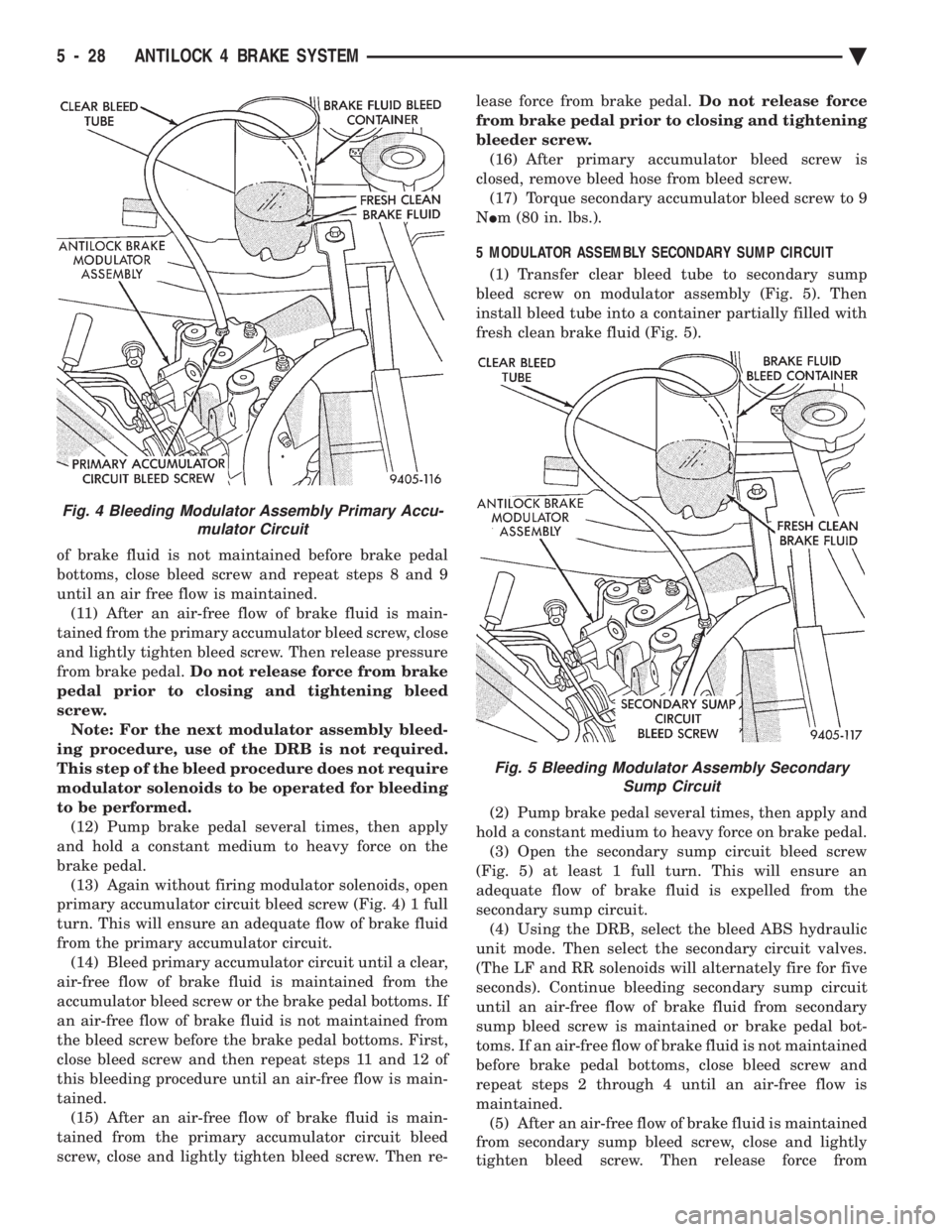
of brake fluid is not maintained before brake pedal
bottoms, close bleed screw and repeat steps 8 and 9
until an air free flow is maintained.(11) After an air-free flow of brake fluid is main-
tained from the primary accumulator bleed screw, close
and lightly tighten bleed screw. Then release pressure
from brake pedal. Do not release force from brake
pedal prior to closing and tightening bleed
screw. Note: For the next modulator assembly bleed-
ing procedure, use of the DRB is not required.
This step of the bleed procedure does not require
modulator solenoids to be operated for bleeding
to be performed. (12) Pump brake pedal several times, then apply
and hold a constant medium to heavy force on the
brake pedal. (13) Again without firing modulator solenoids, open
primary accumulator circuit bleed screw (Fig. 4) 1 full
turn. This will ensure an adequate flow of brake fluid
from the primary accumulator circuit. (14) Bleed primary accumulator circuit until a clear,
air-free flow of brake fluid is maintained from the
accumulator bleed screw or the brake pedal bottoms. If
an air-free flow of brake fluid is not maintained from
the bleed screw before the brake pedal bottoms. First,
close bleed screw and then repeat steps 11 and 12 of
this bleeding procedure until an air-free flow is main-
tained. (15) After an air-free flow of brake fluid is main-
tained from the primary accumulator circuit bleed
screw, close and lightly tighten bleed screw. Then re- lease force from brake pedal.
Do not release force
from brake pedal prior to closing and tightening
bleeder screw. (16) After primary accumulator bleed screw is
closed, remove bleed hose from bleed screw. (17) Torque secondary accumulator bleed screw to 9
N Im (80 in. lbs.).
5 MODULATOR ASSEMBLY SECONDARY SUMP CIRCUIT (1) Transfer clear bleed tube to secondary sump
bleed screw on modulator assembly (Fig. 5). Then
install bleed tube into a container partially filled with
fresh clean brake fluid (Fig. 5).
(2) Pump brake pedal several times, then apply and
hold a constant medium to heavy force on brake pedal. (3) Open the secondary sump circuit bleed screw
(Fig. 5) at least 1 full turn. This will ensure an
adequate flow of brake fluid is expelled from the
secondary sump circuit. (4) Using the DRB, select the bleed ABS hydraulic
unit mode. Then select the secondary circuit valves.
(The LF and RR solenoids will alternately fire for five
seconds). Continue bleeding secondary sump circuit
until an air-free flow of brake fluid from secondary
sump bleed screw is maintained or brake pedal bot-
toms. If an air-free flow of brake fluid is not maintained
before brake pedal bottoms, close bleed screw and
repeat steps 2 through 4 until an air-free flow is
maintained. (5) After an air-free flow of brake fluid is maintained
from secondary sump bleed screw, close and lightly
tighten bleed screw. Then release force from
Fig. 4 Bleeding Modulator Assembly Primary Accu- mulator Circuit
Fig. 5 Bleeding Modulator Assembly SecondarySump Circuit
5 - 28 ANTILOCK 4 BRAKE SYSTEM Ä
Page 315 of 2438
brake pedal. Do not release brake pedal prior to
closing and tightening bleeder screw. (6) After secondary sump bleed screw is closed, re-
move bleed hose from bleed screw. (7) Torque secondary sump bleed screw to 9 N Im (80
in. lbs.).
6 MODULATOR ASSEMBLY SECONDARY ACCUMULATOR
CIRCUIT
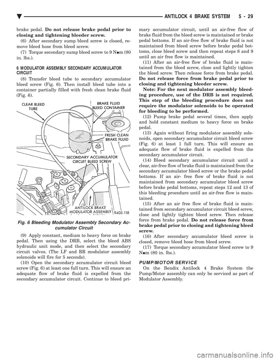
(8) Transfer bleed tube to secondary accumulator
bleed screw (Fig. 6). Then install bleed tube into a
container partially filled with fresh clean brake fluid
(Fig. 6).
(9) Apply constant, medium to heavy force on brake
pedal. Then using the DRB, select the bleed ABS
hydraulic unit mode, and then select the secondary
circuit valves. (The LF and RR modulator assembly
solenoids will fire for 5 seconds). (10) Open the secondary accumulator circuit bleed
screw (Fig. 6) at least one full turn. This will ensure an
adequate flow of brake fluid is expelled from the
secondary accumulator circuit. Continue to bleed pri- mary accumulator circuit, until an air-free flow of
brake fluid from the bleed screw is maintained or brake
pedal bottoms. If an air-free flow of brake fluid is not
maintained from bleed screw before brake pedal bot-
toms, close bleed screw and then repeat steps 8 and 9
until an air free flow is maintained. (11) After an air-free flow of brake fluid is main-
tained from the bleed screw, close and lightly tighten
the bleed screw. Then release force from brake pedal.
Do not release force from brake pedal prior to
closing and tightening bleeder screw. Note: For the next modulator assembly bleed-
ing procedure, use of the DRB is not required.
This step of the bleeding procedure does not
require the modulator solenoids to be operated
for bleeding to be performed. (12) Pump brake pedal several times, then apply
and hold constant medium to heavy force on brake
pedal. (13) Again without firing modulator assembly sole-
noids, open secondary accumulator circuit bleed screw
(Fig. 6) at least 1 full turn. This will ensure an
adequate flow of brake fluid is expelled from the
secondary accumulator circuit. (14) Bleed secondary accumulator circuit until a
clear, air-free flow of brake fluid is maintained from the
secondary accumulator bleed screw or the brake pedal
bottoms. If an air- free flow of brake fluid is not
maintained from secondary accumulator bleed screw
before brake pedal bottoms, repeat steps 12 and 13 of
this bleeding procedure until an air-free flow is main-
tained. (15) After an air free flow of brake fluid is main-
tained from secondary accumulator circuit bleed screw,
close and lightly tighten bleed screw. Then release
force from brake pedal. Do not release force from
brake pedal prior to closing and tightening bleed
screw. (16) After secondary accumulator bleed screw is
closed, remove bleed hose from bleed screw. (17) Torque secondary accumulator bleed screw to 9
N Im (80 in. lbs.).
PUMP/MOTOR SERVICE
On the Bendix Antilock 4 Brake System the
Pump/Motor assembly can only be serviced as part of
Modulator Assembly.
Fig. 6 Bleeding Modulator Assembly Secondary Ac- cumulator Circuit
Ä ANTILOCK 4 BRAKE SYSTEM 5 - 29
Page 333 of 2438
MANUAL TRANSAXLE CLUTCH
CONTENTS
page page
CLEANING PRECAUTIONS ................. 6
CLUTCH CABLE MECHANISM .............. 1
CLUTCH CABLE REPLACEMENT ............ 2
CLUTCH CHATTER COMPLAINTS ........... 1
CLUTCH DISC REPLACEMENT ............. 5
CLUTCH PEDAL NOISE/POP ............... 2 CLUTCH PEDAL POSITION SWITCH
......... 4
EXCESSIVE CLUTCH SPIN TIME/CLASH INTO REVERSE COMPLAINTS ............ 1
GENERAL INFORMATION .................. 1
RELEASE BEARING AND FORK ............. 6
GENERAL INFORMATION
Throughout this group, references may be made to
a particular vehicle by letter or number designation.
A chart showing the breakdown of these designations
is included in the Introduction Section at the front of
this service manual. The clutch used in all models are a single, dry disc
type with no adjustment for wear being provided in
the clutch itself. The clutch pedal is connected to the release shaft
through a cable and lever. The upper end of the clutch pedal pivots in the
pedal bracket on two nylon bushings. These bushings
do not require periodic lubrication.
CLUTCH CHATTER COMPLAINTS
For all clutch chatter complaints, do the following:
(1) Check for loose, misaligned, or broken engine
and transmission mounts. If present, they should be
corrected at this time. Test vehicle for chatter. If
chatter is gone, there is no need to go any further. If
chatter persists: (2) Check to see if clutch cable routing is correct
and operates smoothly. (3) Check for loose connections in drive train. Cor-
rect any problems and determine if clutch chatter
complaints has been satisfied. If not, (4) Remove transaxle. See Group 21, Manual Tran-
saxle, for procedure. (5) Check to see if the release bearing is sticky or
binding. Replace bearing, if needed. (6) Check linkage for excessive wear on bushings.
Replace all worn parts. A small amount of bearing
grease between the release shaft bushings and the
shaft is beneficial, but not required. (7) Check flywheel and clutch pressure plate for
contamination (dirt, oil) or scored. Replace flywheel
and/or pressure plate, if required. (8) Check to see if the clutch disc hub splines are
damaged. Replace with new disc. (9) Check input shaft splines for damage. Replace
if necessary. (10) Check for uneven wear on clutch fingers.
EXCESSIVE CLUTCH SPIN TIME/CLASH INTO
REVERSE COMPLAINTS
For all excessive clutch spin time/clash into reverse
complaints, do the following: (1) Depress clutch pedal to floor and hold. After
three seconds, shift to reverse. If clash is present,
clutch has excessive spin time. (2) Remove transaxle. See Group 21, Manual Tran-
saxle, for procedure. (3) Check the input shaft spline, clutch disc splines
and release bearing for dry rust. If present, clean
rust off and apply a light coat of bearing grease to
the input shaft splines. Apply grease on the input
shaft splines only where the clutch disc slides. (4) Check to see if the clutch disc hub splines are
damaged, replace with new disc if required. (5) Check the input shaft for damaged splines. Re-
place as necessary. (6) Check for excessive clutch disc runout or
warpage. (7) Install clutch assembly and transaxle.
CLUTCH CABLE MECHANISM
The manual transaxle clutch release system has a
unique self-adjusting mechanism to compensate for
clutch disc wear. This adjuster mechanism is located
within the clutch pedal. The preload spring main-
tains tension on the cable. This tension keeps the
clutch release bearing continuously loaded against
the fingers of the clutch cover assembly. When the pedal is depressed, teeth on the adjuster
and the positioner engage and pull the release cable.
A spring located behind the adjuster ensures proper
tooth engagement. When the pedal is released, the adjuster contacts
the bumper. This separates the adjuster and posi-
tioner teeth, allowing the preload spring to function.
Ä MANUAL TRANSAXLE CLUTCH 6 - 1
Page 352 of 2438
SERVICE PROCEDURES INDEX
page page
Automatic Transmission Oil Coolers .......... 23
Coolant ................................ 14
Coolant Recovery System (CRS) ............. 17
Cooling System Drain, Clean, Flush and Refill . . 15
Electric Fan Motor ........................ 22
Engine Thermostats ....................... 13
Fan Shroud ............................. 23 Fans
.................................. 21
Radiator Hoses .......................... 21
Radiator Pressure Cap .................... 18
Radiators ............................... 18
Testing System for Leaks .................. 17
Water Pumps ........................... 10
WATER PUMPS
A quick test to tell whether or not the pump is
working is to see if the heater warms properly. A
defective pump will not be able to circulate heated
coolant through the long heater hose. The water pump on all models can be replaced
without discharging the air conditioning system.
WATER PUMPÐ2.2/2.5L ENGINE
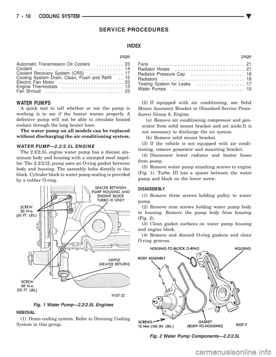
The 2.2/2.5L engine water pump has a diecast alu-
minum body and housing with a stamped steel impel-
ler. The 2.2/2.5L pump uses an O-ring gasket between
body and housing. The assembly bolts directly to the
block. Cylinder block to water pump sealing is provided
by a rubber O-ring.
REMOVAL (1) Drain cooling system. Refer to Draining Cooling
System in this group. (2) If equipped with air conditioning, see Solid
Mount Accessory Bracket in (Standard Service Proce-
dures) Group 9, Engine: (a) Remove air conditioning compressor and gen-
erator from solid mount bracket and set aside.It is
not necessary to discharge the a/c system. (b) Remove solid mount bracket.
(3) If the vehicle is not equipped with air condi-
tioning, remove generator and mounting bracket. (4) Disconnect lower radiator and heater hoses
from pump. (5) Remove water pump attaching screws to engine
(Fig. 1). Turbo III has a spacer between the water
pump and block on the lower screw.
DISASSEMBLY (1) Remove three screws holding pulley to water
pump. (2) Remove nine screws holding water pump body
to housing. Remove the pump body from housing
(Fig. 2). (3) Clean gasket surfaces on water pump housing
and engine block. (4) Remove and discard O-ring gaskets and clean
O-ring grooves.
Fig. 2 Water Pump ComponentsÐ2.2/2.5L
Fig. 1 Water PumpÐ2.2/2.5L Engines
7 - 10 COOLING SYSTEM Ä
Page 359 of 2438
TESTING SYSTEM FOR LEAKS
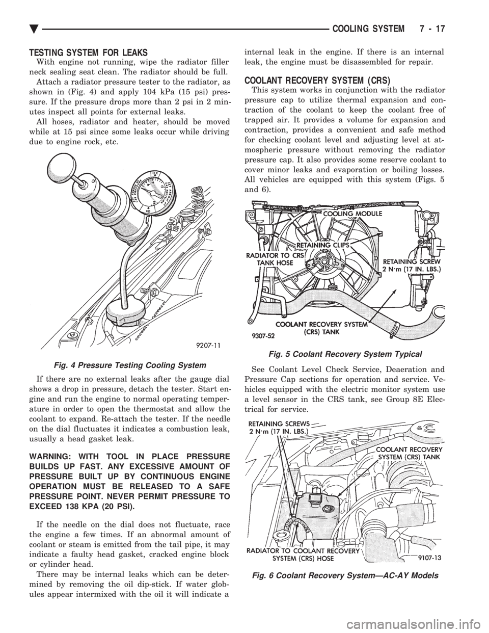
With engine not running, wipe the radiator filler
neck sealing seat clean. The radiator should be full. Attach a radiator pressure tester to the radiator, as
shown in (Fig. 4) and apply 104 kPa (15 psi) pres-
sure. If the pressure drops more than 2 psi in 2 min-
utes inspect all points for external leaks. All hoses, radiator and heater, should be moved
while at 15 psi since some leaks occur while driving
due to engine rock, etc.
If there are no external leaks after the gauge dial
shows a drop in pressure, detach the tester. Start en-
gine and run the engine to normal operating temper-
ature in order to open the thermostat and allow the
coolant to expand. Re-attach the tester. If the needle
on the dial fluctuates it indicates a combustion leak,
usually a head gasket leak.
WARNING: WITH TOOL IN PLACE PRESSURE
BUILDS UP FAST. ANY EXCESSIVE AMOUNT OF
PRESSURE BUILT UP BY CONTINUOUS ENGINE
OPERATION MUST BE RELEASED TO A SAFE
PRESSURE POINT. NEVER PERMIT PRESSURE TO
EXCEED 138 KPA (20 PSI).
If the needle on the dial does not fluctuate, race
the engine a few times. If an abnormal amount of
coolant or steam is emitted from the tail pipe, it may
indicate a faulty head gasket, cracked engine block
or cylinder head. There may be internal leaks which can be deter-
mined by removing the oil dip-stick. If water glob-
ules appear intermixed with the oil it will indicate a internal leak in the engine. If there is an internal
leak, the engine must be disassembled for repair.
COOLANT RECOVERY SYSTEM (CRS)
This system works in conjunction with the radiator
pressure cap to utilize thermal expansion and con-
traction of the coolant to keep the coolant free of
trapped air. It provides a volume for expansion and
contraction, provides a convenient and safe method
for checking coolant level and adjusting level at at-
mospheric pressure without removing the radiator
pressure cap. It also provides some reserve coolant to
cover minor leaks and evaporation or boiling losses.
All vehicles are equipped with this system (Figs. 5
and 6).
See Coolant Level Check Service, Deaeration and
Pressure Cap sections for operation and service. Ve-
hicles equipped with the electric monitor system use
a level sensor in the CRS tank, see Group 8E Elec-
trical for service.
Fig. 4 Pressure Testing Cooling System
Fig. 5 Coolant Recovery System Typical
Fig. 6 Coolant Recovery SystemÐAC-AY Models
Ä COOLING SYSTEM 7 - 17
Page 363 of 2438

RADIATOR HOSES
The hoses are removed using Constant Tension
Clamp pliers to compress hose clamp. A hardened, cracked, swollen or restricted hose
should be replaced. Do not damage radiator inlet and
outlet when loosening hoses. Radiator hoses should be routed without any kinks
and indexed as designed. The use of molded hoses is
recommended. Spring type hose clamps are used in all applica-
tions. If replacement is necessary replace with the
original style spring type clamp.
FANS
All models use electric motor driven cooling system
fans. The fan modules include a motor support which
may (depending on model) include a shroud. The
module is fastened to the radiator by screws with
U-nuts and retaining clips (Fig. 12). All fan motors are one speed. Attempts to reduce
high temperature gauge reading by increasing en-
gine speed, at the same vehicle speed, can increase
high temperature.
SINGLE FAN
There are no repairs to be made to the fan. If the
fan is warped, cracked, or otherwise damaged, it must be replaced with
onlythe recommended part for
adequate strength, performance and safety (Fig. 13).
DUAL FAN MODULEÐAC/AY BODY
The dual fan module (Fig. 11) is a combination of 2
fans mounted in a one piece shroud which are simul-
taneously activated. The dual fan system improves
engine cooling and air conditioning performance in hot
weather and severe driving conditions, while reducing
fan noise and power consumption.
REMOVAL
Disconnect electric motor lead. Remove fan module
to radiator fasteners and retaining clips. Remove as-
sembly from radiator support. To remove fan from motor shaft, bench support the
motor and motor shaft, while removing the fan retain-
ing clip, so that the shaft and motor will not be
damaged by excessive force. Surface or burr re-
moval may be required to remove fan from motor
shaft. (Fig. 13). Do not permit the fan blades to touch
the bench.
INSTALLATION
Slide the fan on motor shaft. Support motor and
shaft as above while installing fan retaining clip.
Install assembly into pocket on lower radiator tank.
Attach retaining clips and fasteners to radiator tank.
Right side fastener is longer on A/C equipped
vehicles . Connect fan motor lead. For wiring dia-
grams of fan motor systems see Wiring Diagrams
Manual
RADIATOR FAN CONTROLÐALL EXCEPT V-6 ENGINE
Fan control is accomplished two ways. The fan al-
ways runs when the air conditioning compressor
clutch is engaged. In addition to this control, the fan is
turned on by the temperature of the coolant which is
sensed by the coolant temperature sensor which
Fig. 12 Servicing Fan Module
Fig. 13 Radiator Fan Retaining ClipÐTypical
Ä COOLING SYSTEM 7 - 21
Page 370 of 2438
ENGINE BLOCK HEATER
DESCRIPTION AND OPERATION
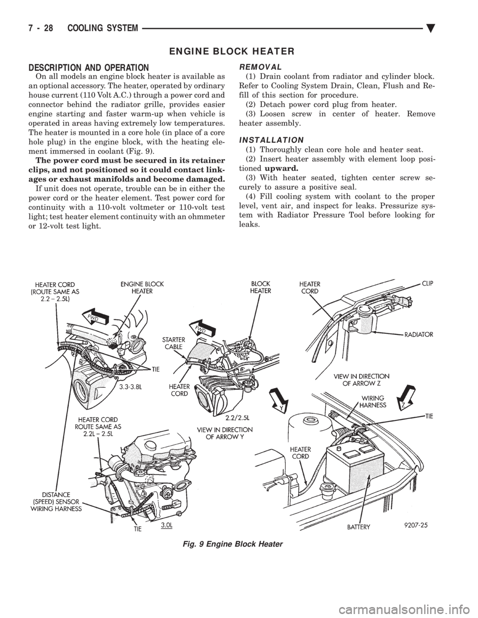
On all models an engine block heater is available as
an optional accessory. The heater, operated by ordinary
house current (110 Volt A.C.) through a power cord and
connector behind the radiator grille, provides easier
engine starting and faster warm-up when vehicle is
operated in areas having extremely low temperatures.
The heater is mounted in a core hole (in place of a core
hole plug) in the engine block, with the heating ele-
ment immersed in coolant (Fig. 9). The power cord must be secured in its retainer
clips, and not positioned so it could contact link-
ages or exhaust manifolds and become damaged. If unit does not operate, trouble can be in either the
power cord or the heater element. Test power cord for
continuity with a 110-volt voltmeter or 110-volt test
light; test heater element continuity with an ohmmeter
or 12-volt test light.
REMOVAL
(1) Drain coolant from radiator and cylinder block.
Refer to Cooling System Drain, Clean, Flush and Re-
fill of this section for procedure. (2) Detach power cord plug from heater.
(3) Loosen screw in center of heater. Remove
heater assembly.
INSTALLATION
(1) Thoroughly clean core hole and heater seat.
(2) Insert heater assembly with element loop posi-
tioned upward.
(3) With heater seated, tighten center screw se-
curely to assure a positive seal. (4) Fill cooling system with coolant to the proper
level, vent air, and inspect for leaks. Pressurize sys-
tem with Radiator Pressure Tool before looking for
leaks.
Fig. 9 Engine Block Heater
7 - 28 COOLING SYSTEM Ä