1993 CHEVROLET DYNASTY ad blue
[x] Cancel search: ad bluePage 633 of 2438
CONDITION: WIPERS START TO WIPE, BUT STOP BEFORE ONE COMPLETE CYCLE ANDDO NOT RETURN TO PARK POSITION
PROCEDURE
(1) Verify that motor will park when the column
switch is put in the OFF position. (2) Set wiper control switch to maximum DELAY
and allow motor to run until it stops during the wipe
cycle. When motor stops, disconnect 25-way blue con-
nector from the body controller. (3) Connect positive lead of voltmeter to pin 20 of
blue connector and negative lead to the metal case of
the body controller. (a) If voltmeter reads 0, check wiring for an open
circuit. (b) If voltmeter reads 10 to 15 volts, proceed to
step 4.
(4) Using an ohmmeter or continuity tester; (a) Check for continuity between pins 20 and 24
of blue connector of the body controller. (b) Reverse ohmmeter leads on pins 20 and 24,
again checking for continuity. (c) If continuity between pins 20 and 24 is not
observed in both steps a and b, replace the body
controller.
CONDITION: EXCESSIVE DELAY OF MORE THAN 30 SECONDS OR INADEQUATEVARIATION IN DELAY
PROCEDURE
(1) Variations in delay should be as follows: (a) Minimum delay control to extreme counter-
clockwise position before first detent of 1/2 to 2 sec-
onds. (b) Maximum delay control to extreme clockwise
position before OFF detent of 15 to 25 seconds.
(2) If there is excessive delay or no variations in
delay, remove the wiper motor wiring harness while
the motor is parked in the OFF position. (3) Remove 25-way blue connector from the body
controller. (4) Set wiper control switch to maximum DELAY
position. (5) With ignition switch in ON position, measure
voltage between pin 9 of black connector and a good
ground. (a) If voltmeter reads 0, proceed to step 6.
(b) If voltmeter reads 10 to 15 volts, proceed to
step 7.
(6) Set wiper control switch to minimum DELAY
position and measure voltage between pin 9 of blue
connector and a good ground. If voltmeter reads 0,
check for an open circuit in the intermittent wipe
wiring harness. (7) Remove wiper motor circuit fuse. (8) Using an ohmmeter, measure the resistance be-
tween pins 9 and 22 of the body controller 25-way
black connector. Set the wiper control switch first to
minimum DELAY and then maximum DELAY. (a) If resistance reading at minimum DELAY
setting is between 0 and 15 ohms, and at maxi-
mum DELAY setting the resistance is between
240,000 and 400,000 ohms, replace the body con-
troller. (b) If the resistance values above are not ob-
tained, replace the wiper control switch.
CONDITION: WIPERS DO NOT RUN CONTINUALLY WHEN WASH CONTROL ISOPERATED DURING DELAY MODE
PROCEDURE
(1) Disconnect 25-way blue connector from the
body controller (2) Using a voltmeter, connect the positive lead to
pin 10 of the (Black) connector. Connect negative
lead to the body computer metal case. (3) Set wiper control switch to DELAY position.
(4) Depress wash switch.
(5) If voltage reads 0, check switch relay and wir-
ing. (6) If voltage is between 10 and 15 volts, the prob-
lem is in the body controller.
CONDITION: IN DELAY MODE, WIPERS RUN CONTINUALLY WHEN WASH IS OPERATEDBUT DO NOT PROVIDE FOUR EXTRA WIPESWHEN WASH CONTROL IS RELEASED
PROCEDURE
Replace body controller.
CONDITION: WIPERS START ERRATICALLY DURING DELAY MODE
PROCEDURE
(1) Verify that the ground connection at the in-
strument panel is making a good connection, free
from paint and is tight. (2) Verify that the motor ground strap is making
good contact and that the motor mounting bolts are
tight. (3) Verify that the wiring connections to the body
controller, wiper motor, and wiper motor switch are
tight and free of corrosion. (4) If condition is not corrected, problem is with
the body controller
Ä WINDSHIELD WIPER AND WASHER SYSTEMS 8K - 13
Page 718 of 2438
CONDITION: NO MEMORY RECALL OF SEAT, RECLINER, OR MIRRORS TO POSITION 1ONLY. UNABLE TO ENTER DIAGNOSTIC SELFTEST MODES. POSITION 2 RECALL WORKS.
PROCEDURE
(1) Check for continuity of actuated memory posi-
tion 1 switch. Refer to the Memory Switch Continu-
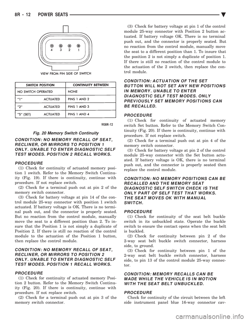
ity (Fig. 19). If there is continuity, continue with
procedure. If not replace switch. (2) Check for a terminal push out at pin 2 of the
memory switch connector. (3) Check for battery voltage at pin 14 of the con-
trol module 25-way connector with position 1 switch
actuated. If battery voltage is OK. There is no termi-
nal push out, and the connector is properly seated.
But no reaction from the control module, manually
move the seat to a different position than 2. To in-
sure that the Position 1 is not simply a duplicate of
Position 2. If there is still no reaction of the control
module to the actuation of the Position 1 button,
then replace the control module.
CONDITION: NO MEMORY RECALL OF SEAT, RECLINER, OR MIRRORS TO POSITION 2ONLY. UNABLE TO ENTER DIAGNOSTIC SELFTEST MODES. POSITION 1 RECALL WORKS.
PROCEDURE
(1) Check for continuity of actuated memory Posi-
tion 2 button. Refer to the Memory Switch Continu-
ity (Fig. 20). If there is continuity, continue with
procedure. If not replace switch. (2) Check for a terminal push out at pin 3 of the
memory switch connector. (3) Check for battery voltage at pin 1 of the control
module 25-way connector with Position 2 button ac-
tuated. If battery voltage OK. There is no terminal
push out, and the connector is properly seated. But
no reaction from the control module, manually move
the seat to a different position than 1. To insure that
the position 2 is not simply a duplicate of position 1.
If there is still no reaction of the control module to
the actuation of the 2 switch, then replace the con-
trol module.
CONDITION: ACTUATION OF THE SET BUTTON WILL NOT SET ANY NEW POSITIONSIN MEMORY. UNABLE TO ENTERDIAGNOSTIC SELF TEST MODES. ONLYPREVIOUSLY SET MEMORY POSITIONS CANBE RECALLED.
PROCEDURE
(1) Check for continuity of actuated memory
switch Set button. Refer to the Memory Switch Con-
tinuity (Fig. 20). If there is continuity, continue with
procedure. If not replace switch. (2) Check for a terminal push out at pin 4 of the
memory switch connector. (3) Check for battery voltage at pin 2 of the control
module 25-way connector with the Set button actu-
ated. If battery voltage is OK, there is no terminal
push out, and the connector is properly seated then
replace the control module.
CONDITION: NO MEMORY POSITIONS CAN BE RECALLED AND THE MEMORY SEATDIAGNOSTIC SELF SWITCH CHECK IS THEONLY PART OF SELF TEST THAT WORKS.THE SEAT MOVES OK WITH MANUALSWITCH.
PROCEDURE
(1) Check for continuity of the seat belt buckle
switch in its unbuckled state. Operate the buckle
switch to ensure the contact opens when the seat belt
is buckled. (2) Check for continuity between pin 2 of the
2-way seat belt buckle switch connector, harness
side, to ground. (3) Check for continuity between pin 1 of the
2-way seat belt buckle switch connector, harness
side, to pin 13 of the control module 25-way connec-
tor.
CONDITION: MEMORY RECALLS CAN BE MADE WHILE THE VEHICLE IS IN MOTIONWITH THE SEAT BELT UNBUCKLED.
PROCEDURE
Check for continuity of the circuit between the left
side instrument panel blue 16-way connector cav-
Fig. 20 Memory Switch Continuity
8R - 12 POWER SEATS Ä
Page 1595 of 2438
(2) Inspect each valve spring for squareness with a
steel square and surface plate, test springs from both
ends. If the spring is more than 1.5mm (1/16 inch)
out of square, install a new spring.
REFACING VALVES AND VALVE SEATS (1) The intake and exhaust valve seats and valve
face have a 45 degree angle.
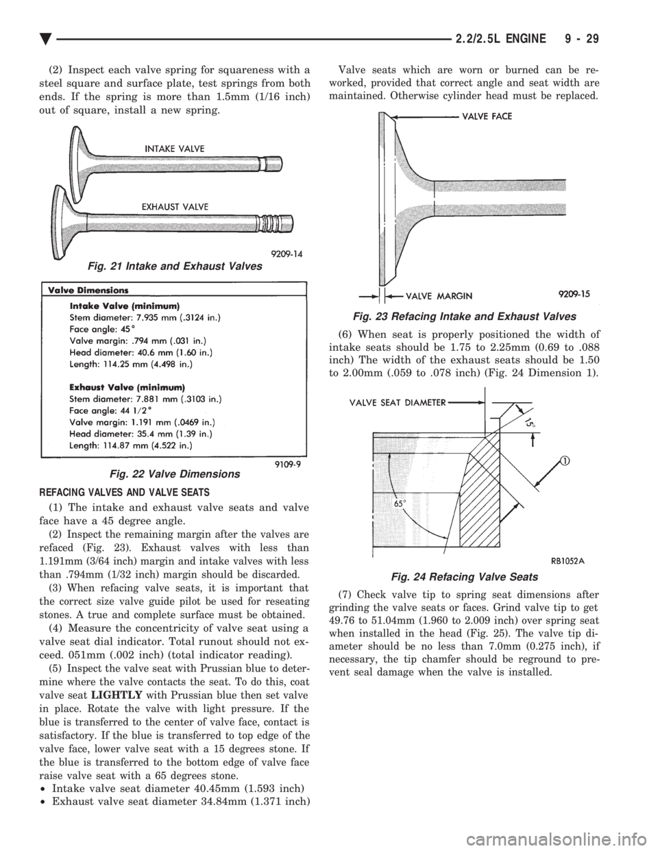
(2) Inspect the remaining margin after the valves are
refaced (Fig. 23). Exhaust valves with less than
1.191mm (3/64 inch) margin and intake valves with less
than .794mm (1/32 inch) margin should be discarded. (3) When refacing valve seats, it is important that
the correct size valve guide pilot be used for reseating
stones. A true and complete surface must be obtained.
(4) Measure the concentricity of valve seat using a
valve seat dial indicator. Total runout should not ex-
ceed. 051mm (.002 inch) (total indicator reading).
(5) Inspect the valve seat with Prussian blue to deter-
mine where the valve contacts the seat. To do this, coat
valve seat LIGHTLY with Prussian blue then set valve
in place. Rotate the valve with light pressure. If the
blue is transferred to the center of valve face, contact is
satisfactory. If the blue is transferred to top edge of the
valve face, lower valve seat with a 15 degrees stone. If
the blue is transferred to the bottom edge of valve face
raise valve seat with a 65 degrees stone.
² Intake valve seat diameter 40.45mm (1.593 inch)
² Exhaust valve seat diameter 34.84mm (1.371 inch)
Valve seats which are worn or burned can be re-
worked, provided that correct angle and seat width are
maintained. Otherwise cylinder head must be replaced.
(6) When seat is properly positioned the width of
intake seats should be 1.75 to 2.25mm (0.69 to .088
inch) The width of the exhaust seats should be 1.50
to 2.00mm (.059 to .078 inch) (Fig. 24 Dimension 1).
(7) Check valve tip to spring seat dimensions after
grinding the valve seats or faces. Grind valve tip to get
49.76 to 51.04mm (1.960 to 2.009 inch) over spring seat
when installed in the head (Fig. 25). The valve tip di-
ameter should be no less than 7.0mm (0.275 inch), if
necessary, the tip chamfer should be reground to pre-
vent seal damage when the valve is installed.
Fig. 21 Intake and Exhaust Valves
Fig. 22 Valve Dimensions
Fig. 23 Refacing Intake and Exhaust Valves
Fig. 24 Refacing Valve Seats
Ä 2.2/2.5L ENGINE 9 - 29
Page 1605 of 2438
REFACING VALVES AND VALVE SEATS
(1) The intake and exhaust valve seats and valve
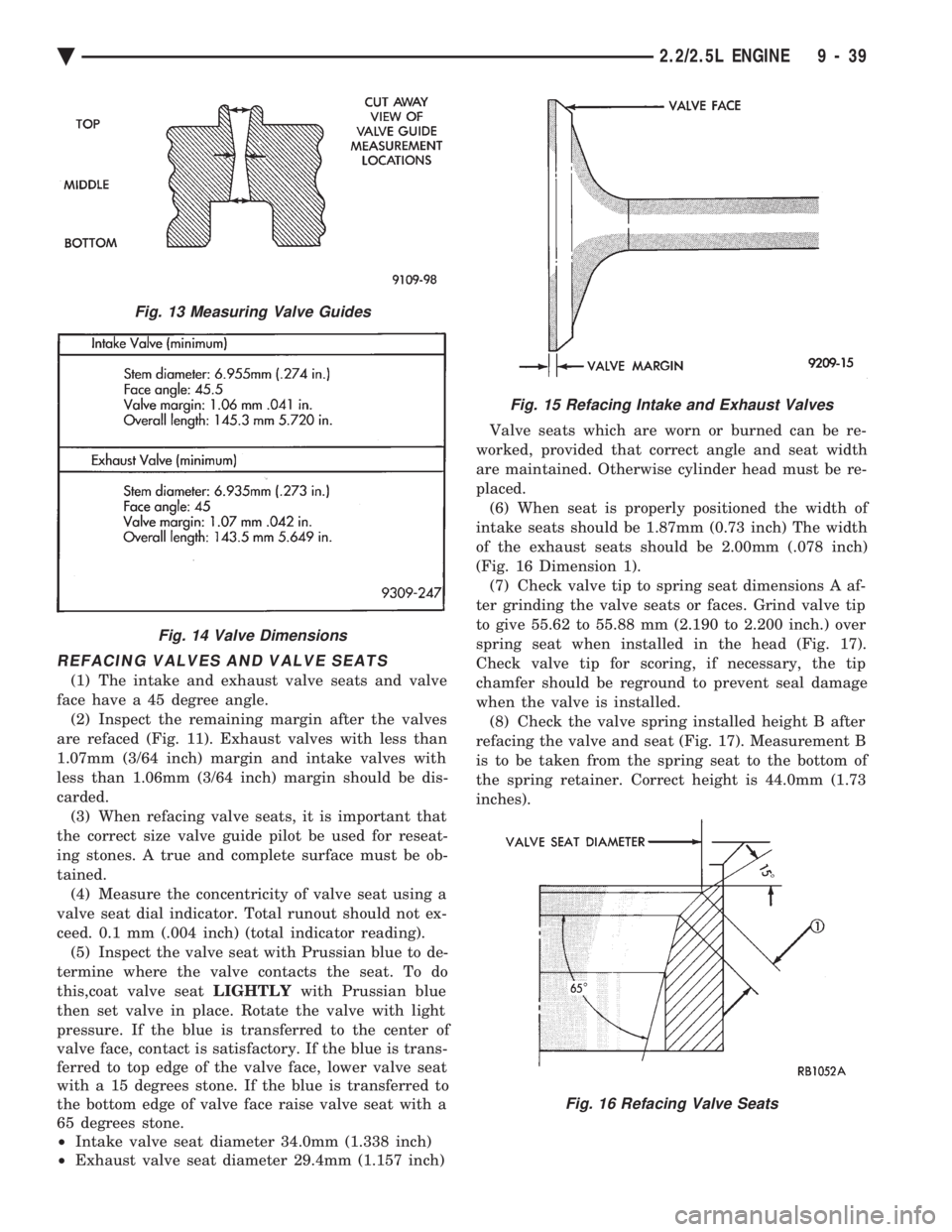
face have a 45 degree angle. (2) Inspect the remaining margin after the valves
are refaced (Fig. 11). Exhaust valves with less than
1.07mm (3/64 inch) margin and intake valves with
less than 1.06mm (3/64 inch) margin should be dis-
carded. (3) When refacing valve seats, it is important that
the correct size valve guide pilot be used for reseat-
ing stones. A true and complete surface must be ob-
tained. (4) Measure the concentricity of valve seat using a
valve seat dial indicator. Total runout should not ex-
ceed. 0.1 mm (.004 inch) (total indicator reading). (5) Inspect the valve seat with Prussian blue to de-
termine where the valve contacts the seat. To do
this,coat valve seat LIGHTLYwith Prussian blue
then set valve in place. Rotate the valve with light
pressure. If the blue is transferred to the center of
valve face, contact is satisfactory. If the blue is trans-
ferred to top edge of the valve face, lower valve seat
with a 15 degrees stone. If the blue is transferred to
the bottom edge of valve face raise valve seat with a
65 degrees stone.
² Intake valve seat diameter 34.0mm (1.338 inch)
² Exhaust valve seat diameter 29.4mm (1.157 inch) Valve seats which are worn or burned can be re-
worked, provided that correct angle and seat width
are maintained. Otherwise cylinder head must be re-
placed. (6) When seat is properly positioned the width of
intake seats should be 1.87mm (0.73 inch) The width
of the exhaust seats should be 2.00mm (.078 inch)
(Fig. 16 Dimension 1). (7) Check valve tip to spring seat dimensions A af-
ter grinding the valve seats or faces. Grind valve tip
to give 55.62 to 55.88 mm (2.190 to 2.200 inch.) over
spring seat when installed in the head (Fig. 17).
Check valve tip for scoring, if necessary, the tip
chamfer should be reground to prevent seal damage
when the valve is installed. (8) Check the valve spring installed height B after
refacing the valve and seat (Fig. 17). Measurement B
is to be taken from the spring seat to the bottom of
the spring retainer. Correct height is 44.0mm (1.73
inches).
Fig. 13 Measuring Valve Guides
Fig. 14 Valve Dimensions
Fig. 15 Refacing Intake and Exhaust Valves
Fig. 16 Refacing Valve Seats
Ä 2.2/2.5L ENGINE 9 - 39
Page 1646 of 2438
INSTALLATION
(1) Clean surfaces of head and block, install head
gasket over locating dowels. (2) Install head on locating dowels.
(3) Install 10mm allen hex head bolts with wash-
ers. (4) Tighten bolts in the order shown in (Fig. 16).
When tightening the cylinder head bolts, tighten
gradually, working in two or three steps and finally
tighten to specified torque of 108 N Im (80 ft. lbs.).
VALVE SERVICE
VALVE AND VALVE SPRINGS
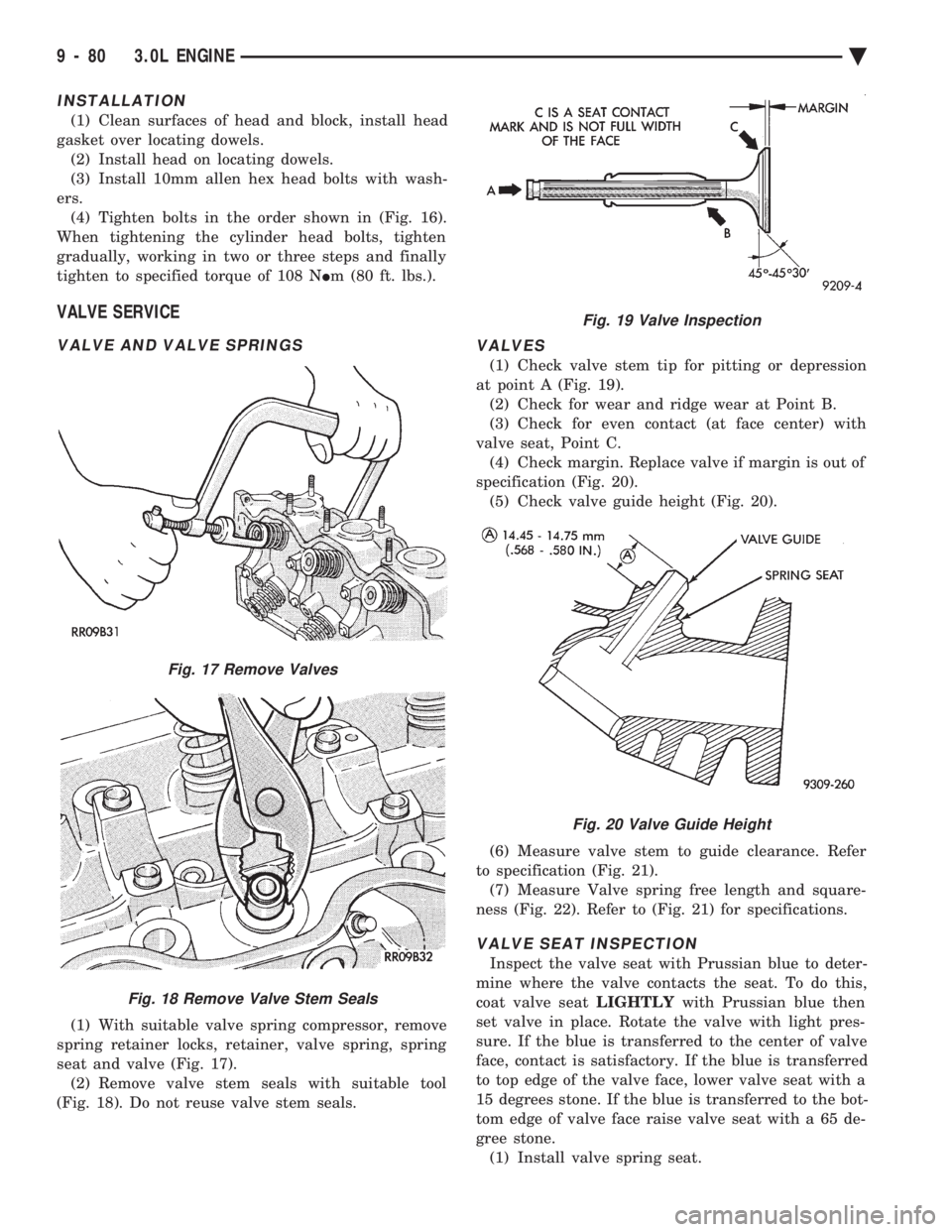
(1) With suitable valve spring compressor, remove
spring retainer locks, retainer, valve spring, spring
seat and valve (Fig. 17). (2) Remove valve stem seals with suitable tool
(Fig. 18). Do not reuse valve stem seals.
VALVES
(1) Check valve stem tip for pitting or depression
at point A (Fig. 19). (2) Check for wear and ridge wear at Point B.
(3) Check for even contact (at face center) with
valve seat, Point C. (4) Check margin. Replace valve if margin is out of
specification (Fig. 20). (5) Check valve guide height (Fig. 20).
(6) Measure valve stem to guide clearance. Refer
to specification (Fig. 21). (7) Measure Valve spring free length and square-
ness (Fig. 22). Refer to (Fig. 21) for specifications.
VALVE SEAT INSPECTION
Inspect the valve seat with Prussian blue to deter-
mine where the valve contacts the seat. To do this,
coat valve seat LIGHTLYwith Prussian blue then
set valve in place. Rotate the valve with light pres-
sure. If the blue is transferred to the center of valve
face, contact is satisfactory. If the blue is transferred
to top edge of the valve face, lower valve seat with a
15 degrees stone. If the blue is transferred to the bot-
tom edge of valve face raise valve seat with a 65 de-
gree stone. (1) Install valve spring seat.
Fig. 17 Remove Valves
Fig. 18 Remove Valve Stem Seals
Fig. 19 Valve Inspection
Fig. 20 Valve Guide Height
9 - 80 3.0L ENGINE Ä
Page 1672 of 2438
REFACING VALVES AND VALVE SEATS
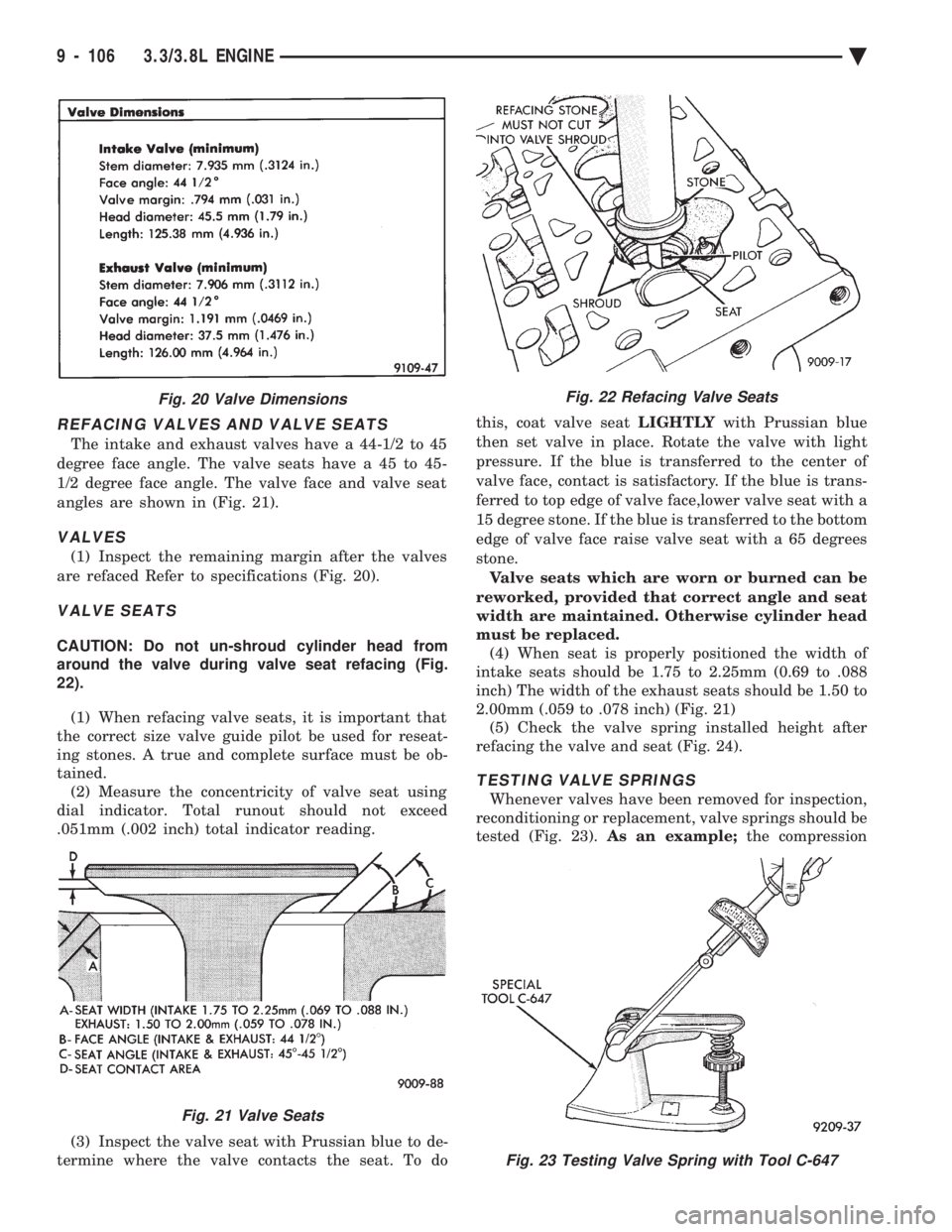
The intake and exhaust valves have a 44-1/2 to 45
degree face angle. The valve seats have a 45 to 45-
1/2 degree face angle. The valve face and valve seat
angles are shown in (Fig. 21).
VALVES
(1) Inspect the remaining margin after the valves
are refaced Refer to specifications (Fig. 20).
VALVE SEATS
CAUTION: Do not un-shroud cylinder head from
around the valve during valve seat refacing (Fig.
22).
(1) When refacing valve seats, it is important that
the correct size valve guide pilot be used for reseat-
ing stones. A true and complete surface must be ob-
tained. (2) Measure the concentricity of valve seat using
dial indicator. Total runout should not exceed
.051mm (.002 inch) total indicator reading.
(3) Inspect the valve seat with Prussian blue to de-
termine where the valve contacts the seat. To do this, coat valve seat
LIGHTLYwith Prussian blue
then set valve in place. Rotate the valve with light
pressure. If the blue is transferred to the center of
valve face, contact is satisfactory. If the blue is trans-
ferred to top edge of valve face,lower valve seat with a
15 degree stone. If the blue is transferred to the bottom
edge of valve face raise valve seat with a 65 degrees
stone. Valve seats which are worn or burned can be
reworked, provided that correct angle and seat
width are maintained. Otherwise cylinder head
must be replaced. (4) When seat is properly positioned the width of
intake seats should be 1.75 to 2.25mm (0.69 to .088
inch) The width of the exhaust seats should be 1.50 to
2.00mm (.059 to .078 inch) (Fig. 21) (5) Check the valve spring installed height after
refacing the valve and seat (Fig. 24).
TESTING VALVE SPRINGS
Whenever valves have been removed for inspection,
reconditioning or replacement, valve springs should be
tested (Fig. 23). As an example; the compression
Fig. 23 Testing Valve Spring with Tool C-647
Fig. 20 Valve Dimensions
Fig. 21 Valve Seats
Fig. 22 Refacing Valve Seats
9 - 106 3.3/3.8L ENGINE Ä
Page 1976 of 2438
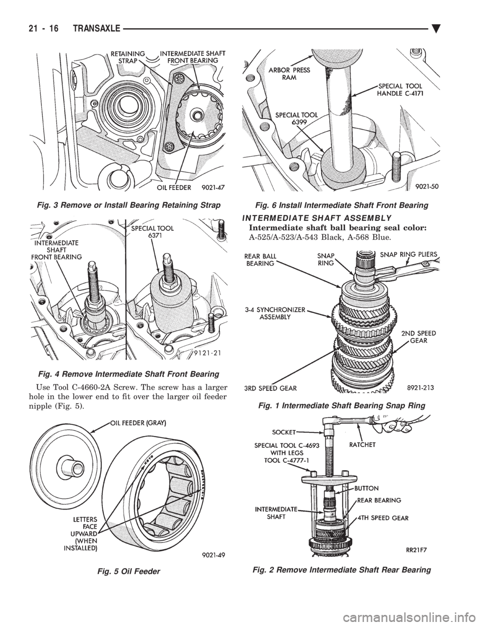
Use Tool C-4660-2A Screw. The screw has a larger
hole in the lower end to fit over the larger oil feeder
nipple (Fig. 5).
INTERMEDIATE SHAFT ASSEMBLY
Intermediate shaft ball bearing seal color:
A-525/A-523/A-543 Black, A-568 Blue.
Fig. 3 Remove or Install Bearing Retaining Strap
Fig. 4 Remove Intermediate Shaft Front Bearing
Fig. 5 Oil Feeder
Fig. 6 Install Intermediate Shaft Front Bearing
Fig. 1 Intermediate Shaft Bearing Snap Ring
Fig. 2 Remove Intermediate Shaft Rear Bearing
21 - 16 TRANSAXLE Ä
Page 2063 of 2438
SPEED SENSOR-OUTPUT
CAUTION: When disconnecting speed sensor con-
nector, be sure that the weather seal does not fall
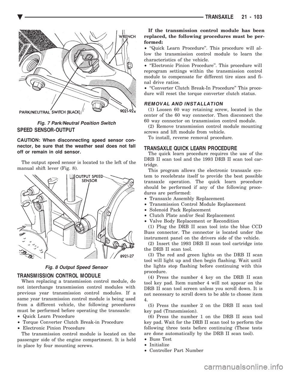
off or remain in old sensor. The output speed sensor is located to the left of the
manual shift lever (Fig. 8).
TRANSMISSION CONTROL MODULE
When replacing a transmission control module, do
not interchange transmission control modules with
previous year transmission control modules. If a
same year transmission control module is being used
from a different vehicle, the following procedures
must be performed before operating the transaxle:
² Quick Learn Procedure
² Torque Converter Clutch Break-in Procedure
² Electronic Pinion Procedure
The transmission control module is located on the
passenger side of the engine compartment. It is held
in place by four mounting screws. If the transmission control module has been
replaced, the following procedures must be per-
formed:
² ``Quick Learn Procedure''. This procedure will al-
low the transmission control module to learn the
characteristics of the vehicle.
² ``Electronic Pinion Procedure''. This procedure will
reprogram settings within the transmission control
module to compensate for different tire sizes and fi-
nal drive ratios.
² ``Converter Clutch Break-In Procedure'' This proce-
dure will reset the torque converter clutch status.
REMOVAL AND INSTALLATION
(1) Loosen 60 way retaining screw, located in the
center of the 60 way connector. Then disconnect the
60 way connector on transmission control module. (2) Remove transmission control module mounting
screws and lift module from vehicle. To install, reverse removal procedure.
TRANSAXLE QUICK LEARN PROCEDURE
The quick learn procedure requires the use of the
DRB II scan tool and the 1993 DRB II scan tool car-
tridge. This program allows the electronic transaxle sys-
tem to recelebrate itself to provide the best possible
transaxle operation. The quick learn procedure
should be performed if any of the following proce-
dures are performed:
² Transaxle Assembly Replacement
² Transmission Control Module Replacement
² Solenoid Pack Replacement
² Clutch Plate and/or Seal Replacement
² Valve Body Replacement or Recondition
(1) Plug the DRB II scan tool into the blue CCD
Buss connector. The connector is located under the
instrument panel on the drivers side of the vehicle. (2) Insert the 1993 DRB II scan tool cartridge into
the DRB II scan tool. (3) The red and green lights on the DRB II scan
tool will light up and then begin flashing. Wait until
the lights stop flashing before continuing with this
procedure. (4) Press the number 4 key on the DRB II scan
tool key pad. Item number 4 will not appear on the
DRB II scan tool screen unless you scroll down. It is
not necessary to scroll down to be able to choose item
4. (5) Press the number 2 on the DRB II scan tool
key pad (Transmission). (6) Press the number 1 on the DRB II scan tool
key pad. Wait for the DRB II scan tool to perform the
following three tests before continuing (These tests
are done automatically by the DRB II scan tool).
² Buss Test
² Initialize
² Controller Part Number
Fig. 7 Park/Neutral Position Switch
Fig. 8 Output Speed Sensor
Ä TRANSAXLE 21 - 103