1993 CHEVROLET DYNASTY turn signal
[x] Cancel search: turn signalPage 1887 of 2438
² transaxle gear selection (park/neutral switch)
The PCM also adjusts engine idle speed through
the idle air control motor based on the following in-
puts.
² brake switch
² engine coolant temperature
² engine speed (crankshaft position sensor)
² throttle position
² transaxle gear selection (park/neutral switch)
² vehicle speed
The auto shutdown (ASD) and fuel pump relays are
mounted externally, but turned on and off by the
PCM through the same circuit. The camshaft position sensor and crankshaft posi-
tion sensor signals are sent to the PCM. If the PCM
does not receive both signals within approximately
one second of engine cranking, it deactivates the
ASD and fuel pump relays. When these relays are
deactivated, power is shut off to the fuel injector, ig-
nition coil, oxygen sensor heating element and fuel
pump. The PCM contains a voltage converter that
changes battery voltage to a regulated 8.0 volts. The
8.0 volts power the camshaft position sensor, crank-
shaft position sensor and vehicle speed sensor. The
PCM also provides a 5.0 volts supply for the coolant
temperature sensor, manifold absolute pressure sen-
sor and throttle position sensor.
AIR CONDITIONING SWITCH SENSEÐPCM INPUT
When the air conditioning or defrost switch is put
in the ON position and the low pressure, high pres-
sure and ambient temperature switches are closed,
the PCM receives an input for air conditioning. After
receiving this input, the PCM activates the A/C com-
pressor clutch by grounding the A/C clutch relay.
BATTERY VOLTAGEÐPCM INPUT
The PCM monitors the battery voltage input to de-
termine fuel injector pulse width and generator field
control. If battery voltage is low the PCM will in-
crease injector pulse width.
BRAKE SWITCHÐPCM INPUT
When the brake switch is activated, the PCM re-
ceives an input indicating that the brakes are being
applied. the brake signal cancels speed control and
unlocks the torque convertor. The brake switch is
mounted on the brake pedal support bracket.
CAMSHAFT POSITION SENSORÐPCM INPUT
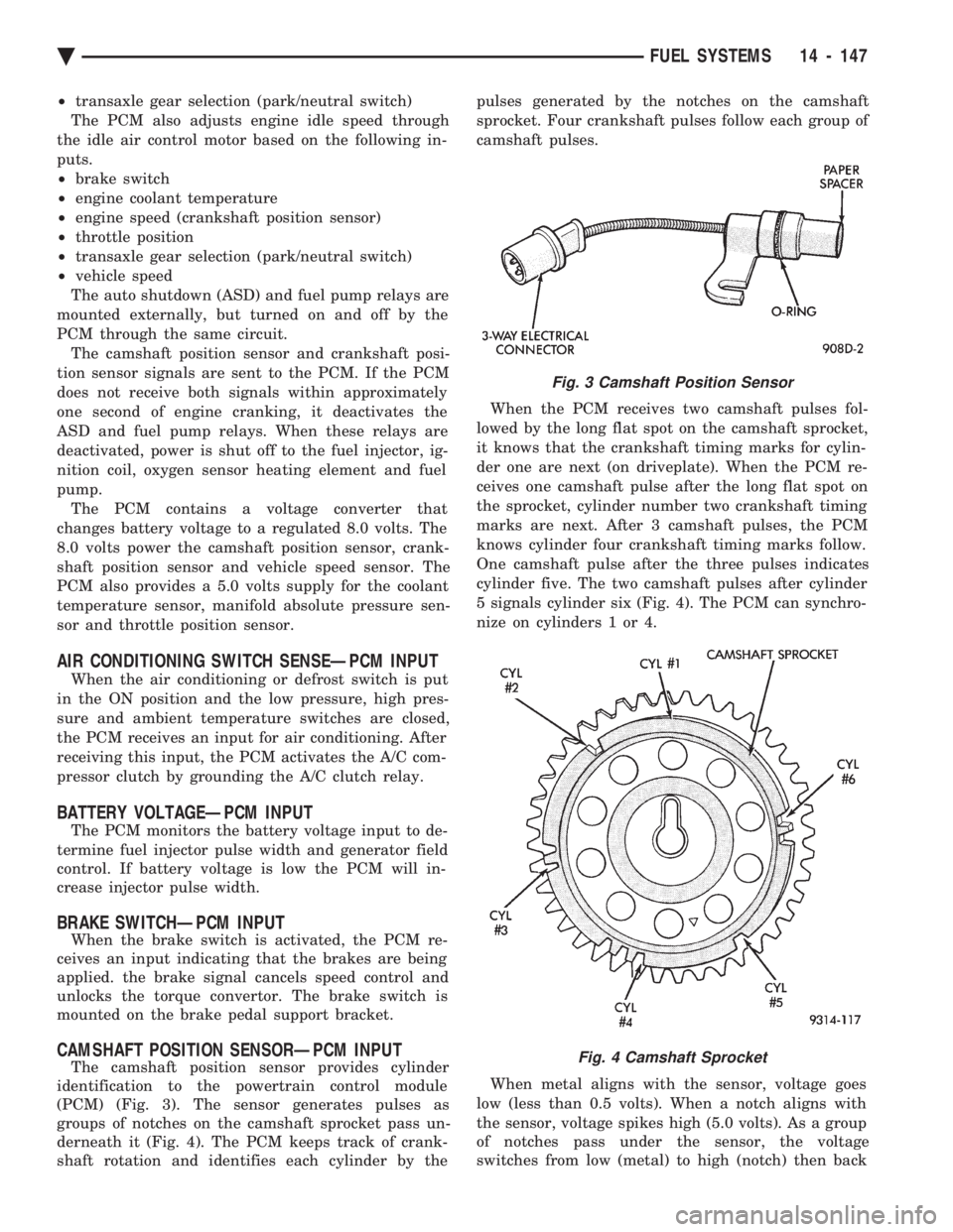
The camshaft position sensor provides cylinder
identification to the powertrain control module
(PCM) (Fig. 3). The sensor generates pulses as
groups of notches on the camshaft sprocket pass un-
derneath it (Fig. 4). The PCM keeps track of crank-
shaft rotation and identifies each cylinder by the pulses generated by the notches on the camshaft
sprocket. Four crankshaft pulses follow each group of
camshaft pulses.
When the PCM receives two camshaft pulses fol-
lowed by the long flat spot on the camshaft sprocket,
it knows that the crankshaft timing marks for cylin-
der one are next (on driveplate). When the PCM re-
ceives one camshaft pulse after the long flat spot on
the sprocket, cylinder number two crankshaft timing
marks are next. After 3 camshaft pulses, the PCM
knows cylinder four crankshaft timing marks follow.
One camshaft pulse after the three pulses indicates
cylinder five. The two camshaft pulses after cylinder
5 signals cylinder six (Fig. 4). The PCM can synchro-
nize on cylinders 1 or 4.
When metal aligns with the sensor, voltage goes
low (less than 0.5 volts). When a notch aligns with
the sensor, voltage spikes high (5.0 volts). As a group
of notches pass under the sensor, the voltage
switches from low (metal) to high (notch) then back
Fig. 3 Camshaft Position Sensor
Fig. 4 Camshaft Sprocket
Ä FUEL SYSTEMS 14 - 147
Page 1891 of 2438
within a range of 12.9 to 15.0 volts. Refer to Group
8A for charging system information.
AUTO SHUTDOWN (ASD) RELAY AND FUEL PUMP
RELAYÐPCM OUTPUT
The PCM operates the auto shutdown (ASD) relay
and fuel pump relay through one ground path. The
PCM operates the relays by switching the ground
path on and off. Both relays turn on and off at the
same time. The ASD relay connects battery voltage to the fuel
injector and ignition coil. The fuel pump relay con-
nects battery voltage to the fuel pump and oxygen
sensor heating element. The PCM turns the ground path off when the igni-
tion switch is in the Off position. Both relays are off.
When the ignition switch is in the On or Crank po-
sition, the PCM monitors the crankshaft position
sensor and camshaft position sensor signals to deter-
mine engine speed and ignition timing (coil dwell). If
the PCM does not receive the crankshaft position
sensor and camshaft position sensor signals when the
ignition switch is in the Run position, it de-energizes
both relays. When the relays are de-energized, bat-
tery voltage is not supplied to the fuel injector, igni-
tion coil, fuel pump and oxygen sensor heating
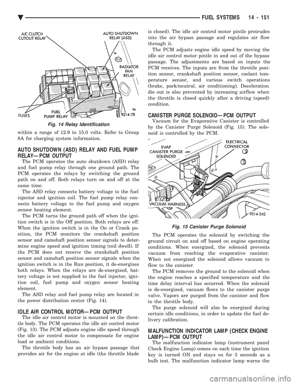
element. The ASD relay and fuel pump relay are located in
the power distribution center (Fig. 14).
IDLE AIR CONTROL MOTORÐPCM OUTPUT
The idle air control motor is mounted on the throt-
tle body. The PCM operates the idle air control motor
(Fig. 13). The PCM adjusts engine idle speed through
the idle air control motor to compensate for engine
load or ambient conditions. The throttle body has an air bypass passage that
provides air for the engine at idle (the throttle blade is closed). The idle air control motor pintle protrudes
into the air bypass passage and regulates air flow
through it. The PCM adjusts engine idle speed by moving the
idle air control motor pintle in and out of the bypass
passage. The adjustments are based on inputs the
PCM receives. The inputs are from the throttle posi-
tion sensor, crankshaft position sensor, coolant tem-
perature sensor, and various switch operations
(brake, park/neutral, air conditioning). Deceleration
die out is also prevented by increasing airflow when
the throttle is closed quickly after a driving (speed)
condition.
CANISTER PURGE SOLENOIDÐPCM OUTPUT
Vacuum for the Evaporative Canister is controlled
by the Canister Purge Solenoid (Fig. 15). The sole-
noid is controlled by the PCM.
The PCM operates the solenoid by switching the
ground circuit on and off based on engine operating
conditions. When energized, the solenoid prevents
vacuum from reaching the evaporative canister.
When not energized the solenoid allows vacuum to
flow to the canister. The PCM removes the ground to the solenoid when
the engine reaches a specified temperature and the
time delay interval has occurred. When the solenoid
is de-energized, vacuum flows to the canister purge
valve. Vapors are purged from the canister and flow
to the throttle body. The purge solenoid will also be energized during
certain idle conditions, in order to update the fuel de-
livery calibration.
MALFUNCTION INDICATOR LAMP (CHECK ENGINE
LAMP)ÐPCM OUTPUT
The malfunction indicator lamp (instrument panel
Check Engine Lamp) comes on each time the ignition
key is turned ON and stays on for 3 seconds as a
bulb test. The malfunction indicator lamp warns the
Fig. 14 Relay Identification
Fig. 15 Canister Purge Solenoid
Ä FUEL SYSTEMS 14 - 151
Page 1894 of 2438
IGNITION SWITCH ON (ZERO RPM) MODE When the multi-port fuel injection system is acti-
vated by the ignition switch, the following actions oc-
cur:
² The PCM determines atmospheric air pressure
from the MAP sensor input to determine basic fuel
strategy.
² The PCM monitors the coolant temperature sensor
and throttle position sensor input. The PCM modifies
fuel strategy based on this input. When the key is in the ON position and the engine
is not running (zero rpm), the auto shutdown (ASD)
relay and fuel pump relay are not energized. There-
fore battery voltage is not supplied to the fuel pump,
ignition coil, fuel injectors or oxygen sensor heating
element.
ENGINE START-UP MODE
This is an OPEN LOOP mode. The following ac-
tions occur when the starter motor is engaged. If the PCM receives the camshaft position sensor
and crankshaft position sensor signals, it energizes
the auto shutdown (ASD) relay and fuel pump relay.
These relays supply battery voltage to the fuel pump,
fuel injectors, ignition coil, and oxygen sensor heat-
ing element. If the PCM does not receive the cam-
shaft position sensor and crankshaft position sensor
signals within approximately one second, it de-ener-
gizes the ASD relay and fuel pump relay. The PCM energizes all six injectors until it deter-
mines crankshaft position from the camshaft position
sensor and crankshaft position sensor signals. The
PCM determines crankshaft position within 1 engine
revolution. After determining crankshaft position, the PCM
begins energizing the injectors in sequence. The PCM
adjusts injector pulse width and controls injector syn-
chronization by turning the individual ground paths
to the injectors On and Off. When the engine idles within 664 RPM of its tar-
get RPM, the PCM compares current MAP sensor
value with the atmospheric pressure value received
during the Ignition Switch On (Zero RPM) mode. If
the PCM does not detect a minimum difference be-
tween the two values, it sets a MAP fault into mem-
ory. Once the ASD and fuel pump relays have been en-
ergized, the PCM:
² Determines injector pulse width based on battery
voltage, coolant temperature, engine rpm and the
number of engine revolutions since cranking was ini-
tiated.
ENGINE WARM-UP MODE This is a OPEN LOOP mode. The following inputs
are received by the PCM:
² engine coolant temperature ²
manifold absolute pressure (MAP)
² engine speed (crankshaft position sensor)
² throttle position
² A/C switch
² battery voltage
The PCM adjusts injector pulse width and controls
injector synchronization by turning the individual
ground paths to the injectors On and Off. The PCM adjusts ignition timing and engine idle
speed. Engine idle speed is adjusted through the idle
air control motor.
CRUISE OR IDLE MODE
When the engine is at operating temperature this
is a CLOSED LOOP mode. During cruising speed the
following inputs are received by the PCM:
² engine coolant temperature
² manifold absolute pressure
² engine speed (crankshaft position sensor)
² throttle position
² exhaust gas oxygen content
² A/C control positions
² battery voltage
The PCM adjusts injector pulse width and controls
injector synchronization by turning the individual
ground paths to the injectors On and Off. The PCM adjusts engine idle speed and ignition
timing. The PCM adjusts the air/fuel ratio according
to the oxygen content in the exhaust gas.
ACCELERATION MODE This is a CLOSED LOOP mode. The PCM recog-
nizes an abrupt increase in throttle position or MAP
pressure as a demand for increased engine output
and vehicle acceleration. The PCM increases injector
pulse width in response to increased fuel demand.
DECELERATION MODE This is a CLOSED LOOP mode. During decelera-
tion the following inputs are received by the PCM:
² engine coolant temperature
² manifold absolute pressure
² engine speed
² throttle position
² exhaust gas oxygen content
² A/C control positions
² battery voltage
The PCM may receive a closed throttle input from
the throttle position sensor (TPS) when it senses an
abrupt decrease in manifold pressure. This indicates
a hard deceleration. The PCM will reduce injector
pulse width. This helps maintain better control of the
air-fuel mixture (as sensed through the O
2sensor).
During a closed throttle deceleration condition, the
PCM grounds the exhaust gas recirculation (EGR)
solenoid. When the solenoid is grounded, EGR func-
tion stops.
14 - 154 FUEL SYSTEMS Ä
Page 1903 of 2438
line. However, these could result in a rich or lean
condition causing an oxygen sensor fault to be stored in
the PCM. Secondary Ignition Circuit - The PCM cannot
detect an inoperative ignition coil, fouled or worn spark
plugs, ignition cross firing, or open spark plug cables. Engine Timing - The PCM cannot detect an incor-
rectly indexed timing chain, camshaft sprocket and
crankshaft sprocket. However, these could result in a
rich or lean condition causing an oxygen sensor fault to
be stored in the PCM. Cylinder Compression - The PCM cannot detect
uneven, low, or high engine cylinder compression. Exhaust System - The PCM cannot detect a
plugged, restricted or leaking exhaust system. Fuel Injector Malfunctions - The PCM cannot
determine if a fuel injector is clogged, the needle is
sticking or the wrong injector is installed. However,
these could result in a rich or lean condition causing an
oxygen sensor fault to be stored in the PCM. Excessive Oil Consumption - Although the PCM
monitors exhaust stream oxygen content when the
system is in closed loop, it cannot determine excessive
oil consumption. Throttle Body Air Flow - The PCM cannot detect a
clogged or restricted air cleaner inlet or filter element. Evaporative System - The PCM will not detect a
restricted, plugged or loaded evaporative purge canis-
ter. Vacuum Assist - Leaks or restrictions in the
vacuum circuits of vacuum assisted engine control
system devices are not monitored by the PCM. How-
ever, these could result in a MAP sensor fault being
stored in the PCM. PCM System Ground - The PCM cannot determine
a poor system ground. However, a diagnostic trouble
code may be generated as a result of this condition. PCM Connector Engagement - The PCM cannot
determine spread or damaged connector pins. How-
ever, a diagnostic trouble code may be generated as a
result of this condition.
HIGH AND LOW LIMITS
The powertrain control module (PCM) compares in-
put signal voltages from each input device with estab-
lished high and low limits for the device. If the input
voltage is not within limits and other diagnostic
trouble code criteria are met, a diagnostic trouble code
will be stored in memory. Other diagnostic trouble code
criteria might include engine RPM limits or input
voltages from other sensors or switches that must be
present before a fault condition can be verified.
DIAGNOSTIC TROUBLE CODE DESCRIPTION
A diagnostic trouble code indicates that the power-
train control module (PCM) has recognized an abnor- mal condition in the system. Diagnostic trouble codes
can be obtained from the malfunction indicator lamp
(Check Engine lamp on the instrument panel) or from
the DRBII scan tool. Diagnostic trouble codes indicate
the results of a failure but do not identify the failed
component directly.
SYSTEM TESTS
WARNING: APPLY PARKING BRAKE AND/OR BLOCK
WHEELS BEFORE PERFORMING ANY TEST ON AN
OPERATING ENGINE.
OBTAINING DIAGNOSTIC TROUBLE CODES
(1) Connect the DRBII scan tool to the data link
connector located in the engine compartment near the
driver side strut tower (Fig. 1). (2) Start the engine if possible, cycle the transaxle
selector and the A/Cswitch if applicable. Shut off the
engine. (3) Turn the ignition switch on, access Read Fault
Screen. Record all the fault messages shown on the
DRBII scan tool. Observe the malfunction indicator
lamp (check engine lamp on the instrument panel). The
lamp should light for 2 seconds then go out (bulb
check). Diagnostic trouble code erasure; access erase
diagnostic trouble code data
STATE DISPLAY TEST MODE
The switch inputs used by the powertrain control
module (PCM) have only two recognized states, HIGH
and LOW. For this reason, the PCM cannot recognize
the difference between a selected switch position ver-
sus an open circuit, a short circuit, or a defective
switch. If the change is displayed, it can be assumed
that the entire switch circuit to the PCM is functional.
From the state display screen access either State
Display Inputs and Outputs or State Display Sensors.
STATE DISPLAY INPUTS AND OUTPUTS
Connect the DRBII scan tool to the vehicle and access
the State Display screen. Then access Inputs and
Outputs. The following is a list of the engine control
system functions accessible through the Inputs and
Outputs screen. Park/Neutral Switch
Speed Control Resume
Brake Switch
Speed Control On/Off
Speed Control Set
A/C Switch Sense
S/C Vent Solenoid
Ä FUEL SYSTEMS 14 - 163
Page 1928 of 2438
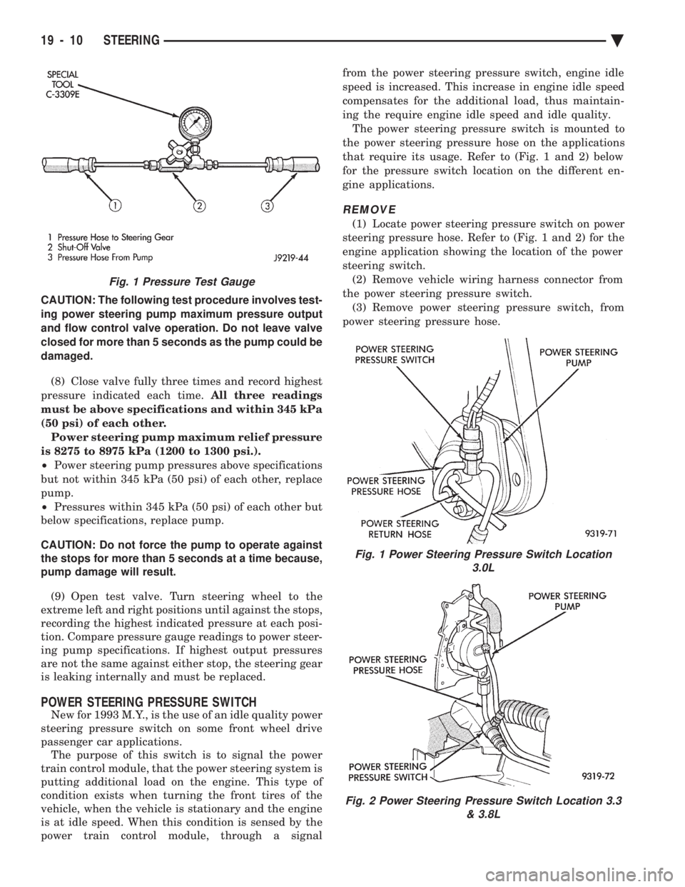
CAUTION: The following test procedure involves test-
ing power steering pump maximum pressure output
and flow control valve operation. Do not leave valve
closed for more than 5 seconds as the pump could be
damaged.
(8) Close valve fully three times and record highest
pressure indicated each time. All three readings
must be above specifications and within 345 kPa
(50 psi) of each other. Power steering pump maximum relief pressure
is 8275 to 8975 kPa (1200 to 1300 psi.).
² Power steering pump pressures above specifications
but not within 345 kPa (50 psi) of each other, replace
pump.
² Pressures within 345 kPa (50 psi) of each other but
below specifications, replace pump.
CAUTION: Do not force the pump to operate against
the stops for more than 5 seconds at a time because,
pump damage will result.
(9) Open test valve. Turn steering wheel to the
extreme left and right positions until against the stops,
recording the highest indicated pressure at each posi-
tion. Compare pressure gauge readings to power steer-
ing pump specifications. If highest output pressures
are not the same against either stop, the steering gear
is leaking internally and must be replaced.
POWER STEERING PRESSURE SWITCH
New for 1993 M.Y., is the use of an idle quality power
steering pressure switch on some front wheel drive
passenger car applications. The purpose of this switch is to signal the power
train control module, that the power steering system is
putting additional load on the engine. This type of
condition exists when turning the front tires of the
vehicle, when the vehicle is stationary and the engine
is at idle speed. When this condition is sensed by the
power train control module, through a signal from the power steering pressure switch, engine idle
speed is increased. This increase in engine idle speed
compensates for the additional load, thus maintain-
ing the require engine idle speed and idle quality.
The power steering pressure switch is mounted to
the power steering pressure hose on the applications
that require its usage. Refer to (Fig. 1 and 2) below
for the pressure switch location on the different en-
gine applications.
REMOVE
(1) Locate power steering pressure switch on power
steering pressure hose. Refer to (Fig. 1 and 2) for the
engine application showing the location of the power
steering switch. (2) Remove vehicle wiring harness connector from
the power steering pressure switch. (3) Remove power steering pressure switch, from
power steering pressure hose.
Fig. 1 Power Steering Pressure Switch Location 3.0L
Fig. 2 Power Steering Pressure Switch Location 3.3 & 3.8L
Fig. 1 Pressure Test Gauge
19 - 10 STEERING Ä
Page 1949 of 2438
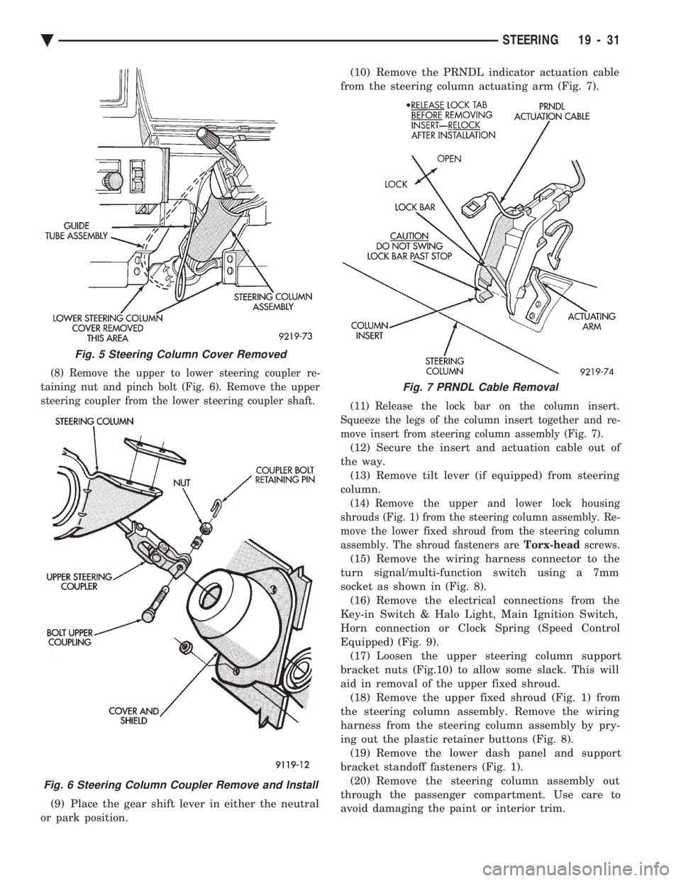
(8) Remove the upper to lower steering coupler re-
taining nut and pinch bolt (Fig. 6). Remove the upper
steering coupler from the lower steering coupler shaft.
(9) Place the gear shift lever in either the neutral
or park position. (10) Remove the PRNDL indicator actuation cable
from the steering column actuating arm (Fig. 7).
(11) Release the lock bar on the column insert.
Squeeze the legs of the column insert together and re-
move insert from steering column assembly (Fig. 7).
(12) Secure the insert and actuation cable out of
the way. (13) Remove tilt lever (if equipped) from steering
column.
(14) Remove the upper and lower lock housing
shrouds (Fig. 1) from the steering column assembly. Re-
move the lower fixed shroud from the steering column
assembly. The shroud fasteners are Torx-headscrews.
(15) Remove the wiring harness connector to the
turn signal/multi-function switch using a 7mm
socket as shown in (Fig. 8). (16) Remove the electrical connections from the
Key-in Switch & Halo Light, Main Ignition Switch,
Horn connection or Clock Spring (Speed Control
Equipped) (Fig. 9). (17) Loosen the upper steering column support
bracket nuts (Fig.10) to allow some slack. This will
aid in removal of the upper fixed shroud. (18) Remove the upper fixed shroud (Fig. 1) from
the steering column assembly. Remove the wiring
harness from the steering column assembly by pry-
ing out the plastic retainer buttons (Fig. 8). (19) Remove the lower dash panel and support
bracket standoff fasteners (Fig. 1). (20) Remove the steering column assembly out
through the passenger compartment. Use care to
avoid damaging the paint or interior trim.
Fig. 5 Steering Column Cover Removed
Fig. 6 Steering Column Coupler Remove and Install
Fig. 7 PRNDL Cable Removal
Ä STEERING 19 - 31
Page 2370 of 2438
AUTOMATIC TEMPERATURE CONTROL (ATC) INDEX
page page
Ambient Temperature Sensor ............... 67
ATC Computer/Control Panel ................ 66
Blend-Air Door Actuator .................... 69
Computer Aided Diagnostic Tests ............ 72
Diagnostic Trouble Code Definitions .......... 73
Diagnostic Trouble Code Service Procedures . . . 74
Erasing Diagnostic Trouble Codes ............ 83
Fresh/Recirc Door Actuator ................. 68 General InformationÐComponent Operation
.... 66
In-Car Temperature Sensor/Aspirator Assembly . . 70
Manual A/C Mode ........................ 66
Mode Door Actuator ...................... 69
NonÐComputer Aided Diagnostic Tests ....... 72
Power Module ........................... 67
Sun Sensor ............................. 71
Water Temperature Sensor ................. 71
GENERAL INFORMATIONÐCOMPONENT
OPERATION
The Automatic Temperature Control (ATC) system
lets the operator change the passenger compartment
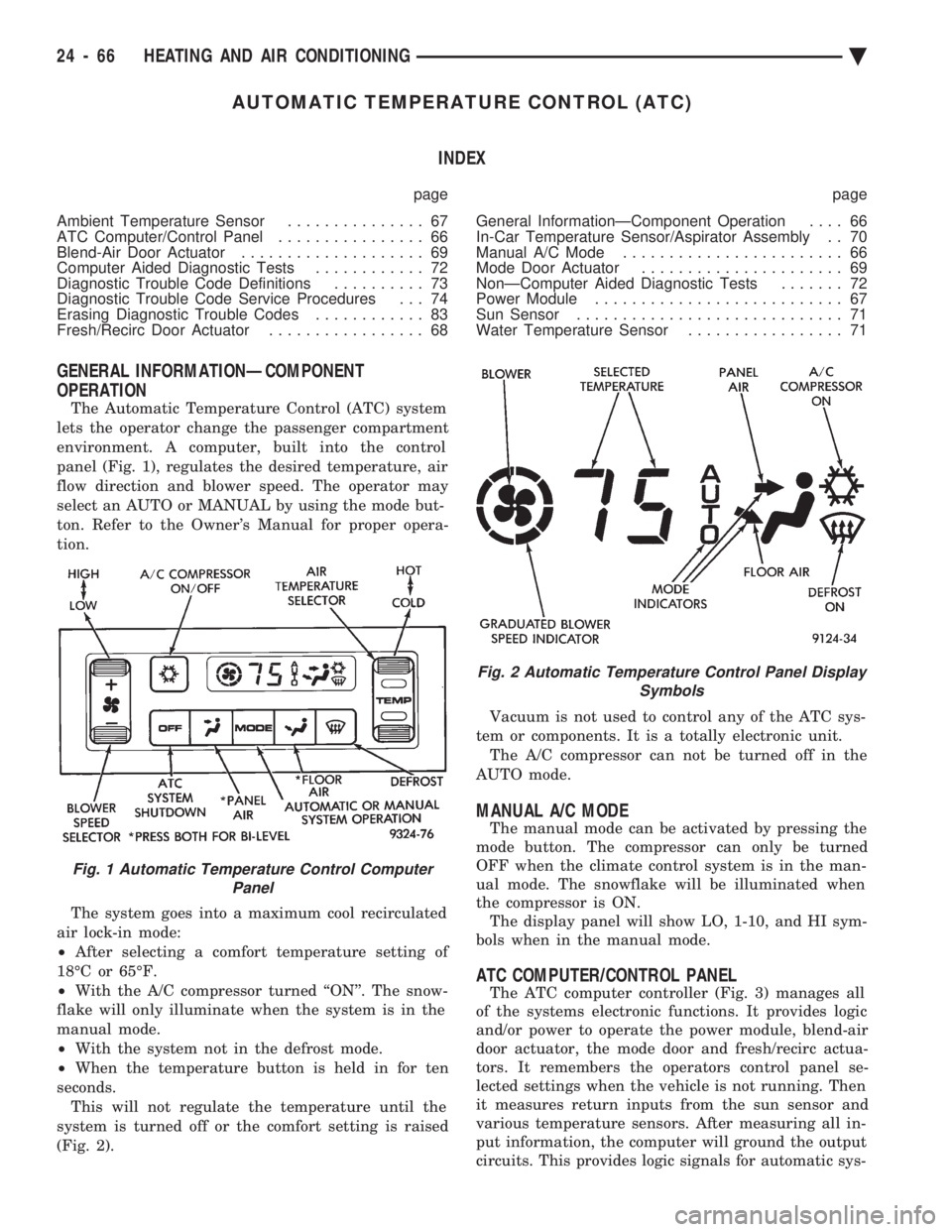
environment. A computer, built into the control
panel (Fig. 1), regulates the desired temperature, air
flow direction and blower speed. The operator may
select an AUTO or MANUAL by using the mode but-
ton. Refer to the Owner's Manual for proper opera-
tion.
The system goes into a maximum cool recirculated
air lock-in mode:
² After selecting a comfort temperature setting of
18ÉC or 65ÉF.
² With the A/C compressor turned ``ON''. The snow-
flake will only illuminate when the system is in the
manual mode.
² With the system not in the defrost mode.
² When the temperature button is held in for ten
seconds. This will not regulate the temperature until the
system is turned off or the comfort setting is raised
(Fig. 2). Vacuum is not used to control any of the ATC sys-
tem or components. It is a totally electronic unit. The A/C compressor can not be turned off in the
AUTO mode.
MANUAL A/C MODE
The manual mode can be activated by pressing the
mode button. The compressor can only be turned
OFF when the climate control system is in the man-
ual mode. The snowflake will be illuminated when
the compressor is ON. The display panel will show LO, 1-10, and HI sym-
bols when in the manual mode.
ATC COMPUTER/CONTROL PANEL
The ATC computer controller (Fig. 3) manages all
of the systems electronic functions. It provides logic
and/or power to operate the power module, blend-air
door actuator, the mode door and fresh/recirc actua-
tors. It remembers the operators control panel se-
lected settings when the vehicle is not running. Then
it measures return inputs from the sun sensor and
various temperature sensors. After measuring all in-
put information, the computer will ground the output
circuits. This provides logic signals for automatic sys-
Fig. 1 Automatic Temperature Control Computer Panel
Fig. 2 Automatic Temperature Control Panel Display Symbols
24 - 66 HEATING AND AIR CONDITIONING Ä
Page 2374 of 2438
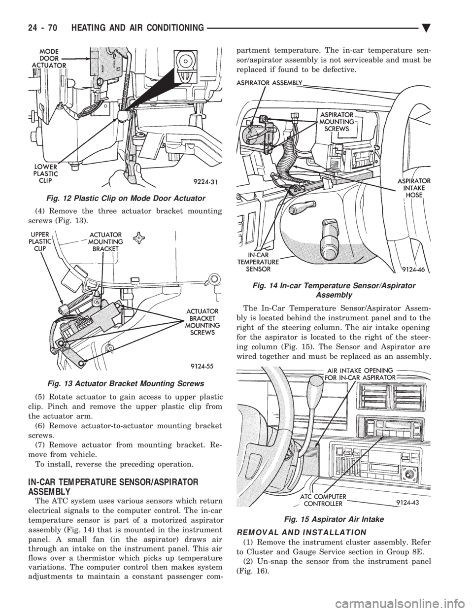
(4) Remove the three actuator bracket mounting
screws (Fig. 13).
(5) Rotate actuator to gain access to upper plastic
clip. Pinch and remove the upper plastic clip from
the actuator arm. (6) Remove actuator-to-actuator mounting bracket
screws. (7) Remove actuator from mounting bracket. Re-
move from vehicle. To install, reverse the preceding operation.
IN-CAR TEMPERATURE SENSOR/ASPIRATOR
ASSEMBLY
The ATC system uses various sensors which return
electrical signals to the computer control. The in-car
temperature sensor is part of a motorized aspirator
assembly (Fig. 14) that is mounted in the instrument
panel. A small fan (in the aspirator) draws air
through an intake on the instrument panel. This air
flows over a thermistor which picks up temperature
variations. The computer control then makes system
adjustments to maintain a constant passenger com- partment temperature. The in-car temperature sen-
sor/aspirator assembly is not serviceable and must be
replaced if found to be defective.
The In-Car Temperature Sensor/Aspirator Assem-
bly is located behind the instrument panel and to the
right of the steering column. The air intake opening
for the aspirator is located to the right of the steer-
ing column (Fig. 15). The Sensor and Aspirator are
wired together and must be replaced as an assembly.
REMOVAL AND INSTALLATION
(1) Remove the instrument cluster assembly. Refer
to Cluster and Gauge Service section in Group 8E. (2) Un-snap the sensor from the instrument panel
(Fig. 16).
Fig. 12 Plastic Clip on Mode Door Actuator
Fig. 13 Actuator Bracket Mounting Screws
Fig. 14 In-car Temperature Sensor/Aspirator Assembly
Fig. 15 Aspirator Air Intake
24 - 70 HEATING AND AIR CONDITIONING Ä