1993 BMW 325i fog
[x] Cancel search: fogPage 432 of 759
612-4
SWITCHES
AND
ELECTRICAL
ACCESSORIES
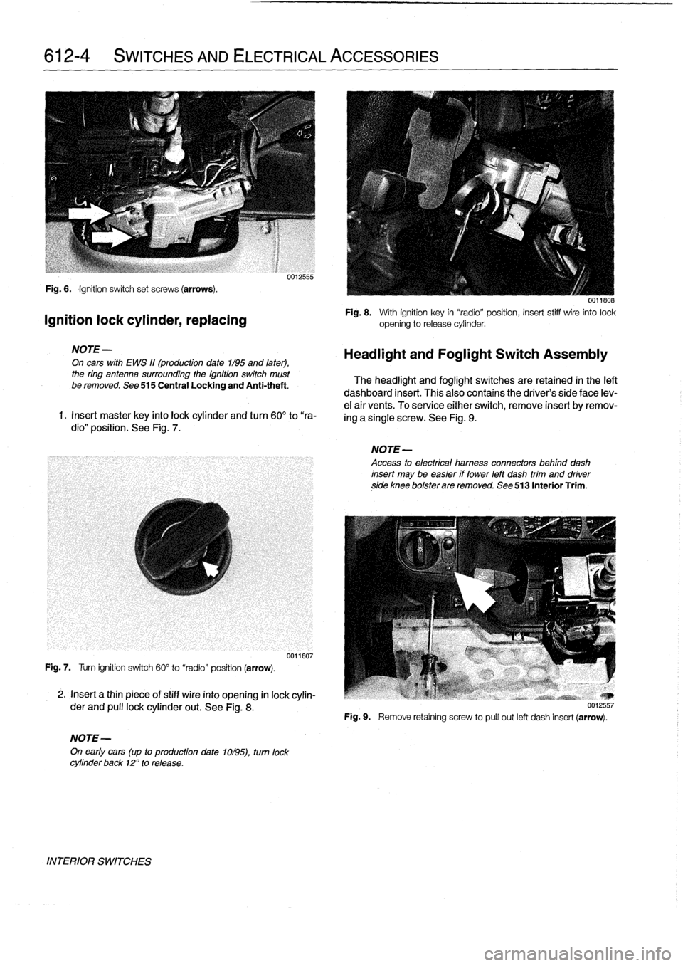
Fig
.
6
.
Ignition
switch
set
screws
(arrows)
.
Ignition
lock
cylinder,
replacing
NOTE-
On
cars
with
EWS
11(production
date
1/95
and
later),
the
ring
antenna
surrounding
the
ignition
switch
must
be
removed
.
See
515
Central
Locking
and
Anti-theft
.
1
.
Insert
master
key
finto
lock
cylinder
and
turn
60°
to
"ra-
dio"
position
.
See
Fig
.
7
.
Fig
.
7
.
Turn
ignition
switch
60°
to
"radio"
position
(arrow)
.
2
.
Insert
a
thin
piece
of
stiff
wire
into
opening
in
lock
cylin-
der
and
pull
lockcylinder
out
.
See
Fig
.
8
.
NOTE-
On
early
cars
(up
to
production
date
1ol95),
turn
lock
cylinder
back
12°
to
release
.
INTERIOR
SWITCHES
0012555
0011807
0011808
Fig
.
8
.
With
ignition
key
in
"radio"position,
insert
stiff
wire
into
lock
opening
to
release
cylinder
.
Headlight
and
Foglight
Switch
Assembly
The
headlight
and
foglight
switches
are
retained
in
the
left
dashboard
insert
.
This
alsocontains
the
driver's
side
face
lev-
e¡
air
vents
.
To
service
either
switch,
remove
insert
byremov-
ing
a
single
screw
.
See
Fig
.
9
.
NOTE-
Access
to
electrical
hamess
connectors
behind
dash
insert
may
be
easier
if
lower
left
dash
trim
and
driverside
knee
bolsterare
removed
.
See
513
Interior
Trim
.
Fig
.
9
.
Remove
retaíning
screw
to
pull
out
left
dash
insert
(arrow)
.
Page 433 of 759

Headlight
switch,
replacing
1
.
Remove
left
side
dash
insert
and
disconnect
harness
connector
to
headlight
switch
.
See
Fig
.
10
.
3
.
Remove
nut
mounting
switch
to
dash
insert
.
See
Fig
.
11
.
Fig
.
11
.
Headlight
switch
mounting
nut
(arrow)
.
4
.
Pull
switch
out
from
housing
.
SWITCHES
AND
ELECTRICAL
ACCESSORIES
612-5
0012558
5
.
Installation
is
reverse
of
removal
.
Align
new
switch
to
dash
insert
.
See
Fig
.
12
.
Tightening
Torque
"
Headlight
switch
retaining
nut
.
......
2
Nm
(18
in-lb)
Foglight
switch,
replacing
0012559
Fig
.
10
.
Removing
headlightswitch
electrical
harness
connector
1
.
Remove
left
side
dash
insert,
as
described
earlier,
and
(arrow)
.
remove
foglight
switch
harness
connector
.
2
.
PA
off
headlight
switch
knob
.
Wrapping
adhesive
tape
aroundknob
facilitates
removal
.
spring
tabs
together
.
0012560
Fig
.
12
.
Fit
groove
on
headlightswitch
into
switch
bezel
ondash
insert
(arrows)
.
2
.
Slide
foglight
switch
out
of
dash
insert
by
sqúeezing
3
.
Installation
is
reverse
of
removal
.
Hazard
warning
switch,
replacing
1
.
Unclip
shift
boot
and
lift
up
from
shift
lever
console
.
Carefully
remove
insulation
pad
.
See
250
Gearshift
Linkage
.
2
.
Working
underneath
center
console,
push
hazard
warning
switch
up
and
out
of
console
with
your
fingers
.
3
.
Disconnect
harness
connector
from
switch
.
4
.
Installation
is
reverse
of
removal
.
Power
window
switch,
replacing
1
.
Unclip
shift
boot
and
lift
up
from
shift
lever
console
.
Carefully
remove
insulation
pad
.
See250
Gearshift
Linkage
.
2
.
Working
underneath
center
console,
push
window
switch
up
out
of
console
with
your
fingers
.
See
Fig
.
13
.
3
.
Disconnect
harness
connector
from
switch
.
4
.
Installation
is
reverse
of
removal
.
INTERIOR
SWITCHES
Page 438 of 759

620-2
INSTRUMENTS
Fig
.1.
Instrument
cluster
retaining
screws
(arrows)
.
INSTRUMENT
CLUSTER
0012562
Fig
.
3
.
Turnbulb
base
45°
in
direction
shown
(arrow)
.
l
v
w
r
v
9
10
11
12
13
14
15
16
)7
18
19
20
y
21
1
.
Temperature
warning
12
.
Brake
fluid
warning
oo13n6
2
.
Right
turn
signal
13
.
Brake
pad
wear
warning
3
.
Instrument
lighting
14
.ABS
warning
Fig
.
2
.
Instrument
cluster
connector
locking
lever
(arrow)
.
4
.
Oil
pressure
warning
15
.
Seat
belt
warning5
.
Highbeam
16
.ASTwarning
6
.
Battery
charging
lamp
17
.Check
control
6
.
Installation
is
reverse
of
removal,
noting
the
following
:
7
.
Left
turn
signal
18
.Check
engine
"
Instrument
cluster
harness
connector
locking
levers
8
.
Low
fuel
warning
19
.
LCD
lighting
must
be
in
up
position
before
installing
connector
.
9
.
Airbag
warning
20
.
Rear
foglight
(not
used)
10
.
Catalytic
converter
warning
21
.
Front
foglights
"
Install
airbag
to
steering
wheel
as
described
in
721
11
.
Emergency
brake
Airbag
System
(SRS)
.
0012563
"
Reconnect
negative
(-)
cable
to
battery
last,
once
al¡
Fig
.
4
.
Bulb
designation
chart
.
harness
connectors
have
been
reconnected
.
"
Recode
cluster
as
described
in
Instrument
cluster,
CAUTION-
seif-testing
.
Note
wattage
of
bulb
.
Excessive
wattage
could
melt
cluster
housing
.
Replace
defective
bulbs
with
Instrument
cluster
bulbs,
replacing
reptacementbulbs
of
the
same
wattage
.
1
.
Remove
instrument
cluster
as
described
above
.
Odometer
coding
plug,
replacing
2
.
Remove
faulty
bulb
by
turning
bulb
base
45°
inits
mount
and
remove
from
housing
.
See
Fig
.
3
.
The
coding
plug
maintains
a
record
of
thevehicle
mileage
.
The
back
of
the
instrument
cluster
and
its
bulb
locations
are
1
.
Record
vehicle
mileage
.
shown
in
Fig
.
4
.
2
.
Remove
instrument
cluster
as
described
earlier
.
Page 441 of 759

FRONT
LIGHTING
.
...........
.
....
.
.
.
.
630-1
Headlight
buib,
replacing
............
.
.
.
.
630-1
Headlight
assembly,
removing
and
installing
.......
.
....
.
.
.
.
630-2
Foglight
assembly,
removing
and
installing
..
630-3
Front
turn
signal
assembly,
removing
and
installing
.....
.
.
.
........
630-4
GENERAL
The
headlight
and
foglight
assemblies
usehalogen
bulbs
.
To
ensure
the
longevity
of
halogen
bulbs,
the
bulb
glass
should
not
be
handied
.
Dirt
and
skin
oíls
may
cause
a
bulbto
fail
prematurely
.
If
necessarywipe
bulb
using
a
clean
cloth
dampened
with
rubbing
alcohol
.
NOTE-
Use
only
original
equipment
replacement
bulbs
.
Non-
original
equipment
bulbs
may
cause
false
failure
read-
ings
on
the
check
control
display
(where
applicable)
.
WARNING
-
INhenworking
on
electrical
systems,
remove
the
fuse
protecting
the
circuit
under
repair
.
See
610
Electrical
Component
Locations
.
FRONT
LIGHTING
Headlight
bulb,
replacing
1
.
Open
engine
hood
.
2
.
Working
in
back
of
headlight
assembly,grasp
rear
of
bulbsocket
(harnessconnector)
and
turn
counterclock-
wise
90°
.
Pull
bulb
out
of
headlight
assembly
.
See
Fig
.
1
.
3
.
Disconnect
harness
connector
from
bulb
.
CA
UTION-
Do
not
touch
halogen
bubs
with
yourbare
hands
.
If
necessary
wipe
bulb
using
a
clean
cloth
damp-
ened
with
rubbing
alcohol
.
630
Exterior
Lighting
EXTERIOR
LIGHTING
630-1
GENERAL
.
.
.
.
...
.
................
.
.
.
.
630-1
Side
Marker
Lights
.......
.
.
.
.
.
.......
.
..
630-4
REAR
LIGHTING
.
......
.
.
.
.
.
.
.
...
.
.
.
..
630-4
Taillight
Bulbs
..........
.
.
.
.
.
.....
.
.
.
.
.
630-4
Taillight
assembly,
removing
and
installing
.
.
.
630-5
CenterBrake
Light
.......
.
.
.
.
.
.
.
.
.
.
.
.
.
.
.
630-5
Center
brake
light
housing,
replacing
(4-door
and
coupe
models)
.
.
.
.
.......
.
.
.630-5
License
plate
light,
removingand
installing
.
.630-6
0012567
Fig
.1.
Torelease
bulbfrom
headlight
assembly,
rotate
socket
coun-
terclockwise
to
disengage
retaining
tabs
(arrows)
.
Right
side
bulb
is
shown
in
unlocked
position
.
Note
that
bottom
tab
A
is
wider
than
other
two
.
4
.
Installation
is
reverse
of
removal
.
Align
tabs
on
bulb
base
to
cutouts
on
rear
of
lens
assembly
.
Secure
bulb
by
rotating
clockwise
90°
.
Bulb
Applications
"
Low
beam
headlight
bulb
...
.
..
..
.........
H9006
"
High
beam
headlight
bulb
..
.
..
..
.........
H9005
FRONT
LIGHTING
Page 443 of 759

4
Foglight
assembly,
removing
and
installing
1
.
Foglight
lens
release
catch
2
.
Foglight
lensrear
protective
cap
3
.
Foglight
bulb
4
.
Foglight
lens
Fig
.
7
.
Foglight
assembly
(removed)
.
0012682
Fig
.
6
.
Measure
gap
B
(1.5
mm)
between
front
of
hood
and
headlight
cover
.
Note
horizontal
headlightadjusting
nut
(1)
and
retaining
screw
(2)
.
The
following
procedure
covers
foglight
lens
and
foglight
buib
replacement
.
Foglight
components
are
shown
in
Fig
.
7
.
0012683
EXTERIOR
LIGHTING
630-
3
1
.
Insert
a
screwdriver
in
upper
air
duct
inlet
of
front
lower
valence
and
disengage
foglight
lens
catch
mechanism
.
Swing
light
outward
and
gently
disengage
hinged
end
.
See
Fig
.
8
.
Fig
.
8
.
Insert
screwdriver
in
upper
air
duct
inlet
.
uu¡¿biu
2
.
Remove
rear
protection
capand
disengage
steel
wire
foglight
bulb
clamp
.
3
.
Remove
bulb
from
rear
of
foglight
assembly
.
Discon-
nect
electrical
harness
from
foglight
bulb
.
CAUTION
-
Do
not
touch
halogen
bulbs
with
yourbare
hands
.
If
necessary
wipe
buib
using
a
clean
cloth
damp-ened
withrubbing
alcohol
.
4
.
Installation
is
reverse
of
removal
.
Check
electrical
con-nector
for
corrosion
.
Spray
with
contact
cleaner,
if
nec-
essary
.
Bulb
Application
(USA
Models)
:
"
Foglight
bulb
......
...
..
...
..........
Hl
(55w)
FRONT
LIGHTING
Page 447 of 759

GENERAL
E36
cars
are
equipped
with
integrated
automatic
heating
and
air
conditioning
systems
.
Many
of
the
procedures
given
in
this
repair
group
require
that
the
A/C
refrigerant
charge
be
evacuated
using
specialized
equipment
.
See
A/C
System
Warningsand
Cautions
later
in
this
repair
group
.
HEATER
AND
CONTROLS
Blower
motor,
removing
and
installing
NOTE-
On
6-cylinder
cars,
the
plastic
top
enginecover
and
fuel
rail
covermustbe
removed
.
The
fuel
injectorhamess
re-
taining
screws
must
be
removed
and
the
harness
set
aside
.
The
engine
control
module
(ECM)
cover
must
be
removed,
the
control
unit
connectors
unplugged
and
the
harness
pulled
out
of
the
way
.
See
130
Fuel
Injection
.
1
.
Disconnect
negative
(-)
cable
from
battery
.
2
.
Open
hood
.
Unclip
engine
bulkhead
plenum
grille
at
base
of
windshíeld
and
remove
grille
.
See
Fig
.
1
.
HEATING
AND
AIR
CONDITIONING
640-1
640
Heating
and
Air
Conditioning
GENERAL
.
...
.
....
.
.
.
.
.
.
.
.
.
.......
.
.
.
640-1
Heater
andA/C
air
distribution
motor,
replacing(rotary-knob)
.
.
...
.
.
.
.......
.
640-10
HEATER
AND
CONTROLS
.
.....
.
.
.
.
.
.
.640-1
Rear
Window
Defogger
.
.
.
.
.
.
.
.
.
.
...
.
.
.
640-10
Blower
motor,
removing
and
installing
.
.
.
.
.
.
640-1
Rear
Window
Blower
(convertible
models)
.
.640-10
Blowermotor
resistor
pack,
replacing
.
.
.
.
.
.
640-3
AIR
CONDITIONING
.
.
.
.
.
.
.
.
.
.
.
.
.
.
.
.
.
.
640-11
Heater
valve,
replacing
...........
.
.
.
.
.
.
.
640-3
Heater
box,
removing
and
installing
.
.
.
.
.
.
.
.
640-4
A/CSystem
Warnings
and
Cautions
.
.
.
.
.
.
:640-11
Heater
core,
replacing
.....
.
.
:
....
.
.
.
.
.
.
.
640-6
A/C
compressor,
replacing
.
.
::.
:
:
.
.
.
.
.
.
.
.640-12
Heater
core
temperature
sensor,
replacing
.
.
640-7
A/C
Compressor
Clutch
.
.
.
.
.
.
.
:
.
.
.
.
.
.
.
.
.
640-13
Heater
andA/C
Control
Head
.
.
....
.
.....
.
640-7
A/C
condenser,
replacing
.
.
.
.
.
.
.
.
.
.
.
.
.
.
.
.
640-14
Heater
andA/C
control
head,
removing
A/C
receiver/drier,
replacing
.
.
.
.
.
.
.
.
.
.
.
.
.
640-15
and
installing
(rotary-knob)
.
.
....
.
......
640-7
A/C
expansion
valve,
Heater
andA/C
control
head,
removing
removing
and
installing
...
.
.....
.
.
.
.
.
.
.
640-16
and
installing
(digital-display)
.
.....
.
.....
640-8
A/C
evaporator,
removing
and
installing
.
.
..
640-17
Heater
andA/C
control
module,removing
A/C
evaporator
temperature
sensor,
and
installing
(rotary-knob)
.
.
...
.
.
.
.
.
.
.
.
640-8
replacing
.
.
.
.
.
.
..............
.
.
.
.
.
..
640-17
Heater
andA/C
control
module,removing
A/C
microfilter,
replacing
......
.
....
.
.
.
..
640-18
and
installing
(digital-display)
.
...
.
.
.
.
.
...
640-8
Sensor
fan
for
interior
temperature,
TABLES
replacing
.
.
.
....
.
.
.
.
.
.
.
.
.
.
.
.
.
.
.
.
.
.
.
.
640-9
a
.
Blower
Motor
Test
Values
.........
...
.
.
......
640-3
Heater
andA/C
AirDistribution
Motors
.
.
.
.
.
.
640-9
b
.
Heater
Core
Temperature
Sensor
Test
Values
...
.640-7
c
.
Evaporative
Temperature
Sensor
Test
Values
...
640-17
d
.
A/C
System
Fluid
Capacities
(total)
..
..........
640-18
0012527
Fig
.
1
.
Detach
grille
retaining
clips
(arrows)
and
pull
grille
upward
and
out
of
rubbergasket
.
CAUTION-
Prior
to
disconnectiog
the
battery,
read
the
battery
disconnection
cautionsgiven
at
the
front
of
this
manual
onpage
viii
.
HEATER
AND
CONTROLS
Page 456 of 759
640-10
HEATING
AND
AIR
CONDITIONING
i
El
Radio
Antenna
Rear
.
,
si,-
Left
side
I
d
1
.
Rear
vents
2
.
Fresh
air
3
.
Face-level
vents
4
.
Recirculation
5
.
Footwell
vents
0013017
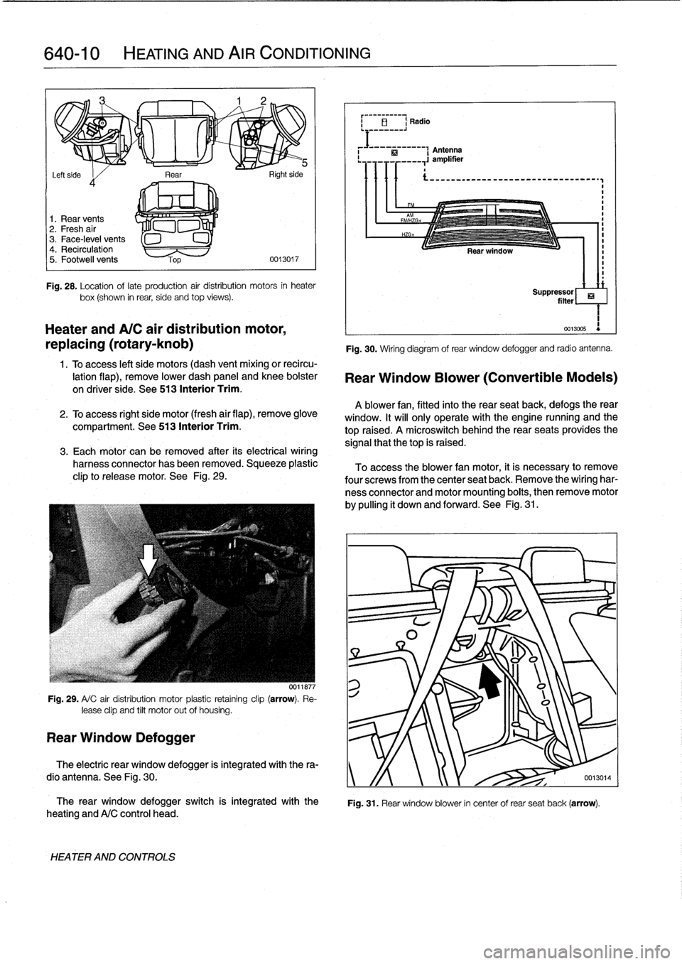
Fig
.
28
.
Location
oflate
production
air
distribution
motors
in
heater
box(shown
in
rear,
side
and
top
views)
.
Heater
andA/C
air
distribution
motor,
replacing
(rotary-knob)
1
.
Toaccess
left
side
motors
(dash
vent
mixing
or
recircu-
lation
flap),
remove
lower
dash
panel
and
knee
bolster
on
driver
side
.
See
513
Interior
Trim
.
2
.
To
access
right
side
motor
(fresh
air
flap),
remove
glove
compartment
.
See513
Interior
Trim
.
3
.
Each
motor
can
be
removed
after
its
electrical
wiring
harness
connector
has
been
removed
.
Squeeze
plastic
clip
to
release
motor
.
See
Fig
.
29
.
Fig
.
29
.
A/
C
air
distribution
motor
plastic
retaíning
clip
(arrow)
.
Re-
lease
clip
and
tilt
motor
out
of
housing
.
Rear
Window
Defogger
0011877
The
rear
window
defogger
switch
is
integrated
with
the
heating
andA/C
control
head
.
HEATER
AND
CONTROLS
Fig
.
30
.
Wiring
diagram
of
rear
window
defogger
and
radio
antenna
.
Rear
Window
Blower
(Convertible
Models)
A
blower
fan,
fitted
into
the
rear
seatback,
defogs
therear
window
.
It
will
only
operate
with
the
engine
nunning
and
the
top
raised
.
A
microswitch
behindthe
rear
seats
provides
the
signal
that
thetop
is
raised
.
To
access
the
blower
fan
motor,
it
is
necessary
to
remove
four
screwsfrom
the
center
seat
back
.
Remove
the
wiring
har-
ness
connector
and
motor
mounting
boits,
then
remove
motor
by
pulling
it
down
and
forward
.
See
Fig
.
31
.
ri
Suppressor
filter
1
0013005
Fig
.
31
.
Rear
window
blower
in
center
of
rear
seat
back
(arrow)
.
The
electric
rear
window
defogger
is
integrated
with
the
ra-
dio
antenna
.
See
Fig
.
30
.
y
/f
0013014
Page 465 of 759

GENERAL
.........
.
.......
.
.
.
.
.
.
.
.
.
..
650-1
Rear
speaker,
removing
and
installing
.
.
.
.
.
.650-5
Door
panel
speaker,
AUDIO
SYSTEM
............
.
.
.
.
.
.
.
.
.
..
650-1
removing
and
installing
.
.
.
.
.....
.
.
.
.
.
.
.
.650-5
Radio
connector
..
.
.
.
.
.
.
.
.
.
.......
.
.
.
.
.
.
650-6
RADIO
AND
SPEAKER
SERVICE
.
.
.
.
.
..
650-2
Radio,
removingand
installing
.
.
.
.
.
.
...
.
..
650-2
Left
footwell
speaker,
removing
and
installing
.
....
.
.
.
.....
.
.
.
650-3
Right
footwell
speaker,
removing
and
installing
.
....
.
.
.
.....
.
..
650-4
GENERAL
AUDIO
SYSTEM
Thissection
coversthe
BMW
factory-installed
sound
sys-
The
BMW
E36
is
equipped
with
a
three
band
radio/cassette
tem,
including
radio
and
speaker
removal,
radio
connectors
player
unit
mounted
in
the
middle
of
thecenter
console
.
In
ad
and
terminal
designations
.
dítion
to
AM
and
FM
bands,
the
radio
will
receive
broadcasts
from
theNational
Weather
Service
.
The
antenna
is
incorporated
into
the
rear
window
defogger
.
650
Radio
Fig
.
1
.
Radio
amplifier
(premiumpackage)
in
luggage
compartment
behind
left
panel
.
RADIO
650-1
TABLE
a
.
Radio
Connector
Terminal
Designation
...
.
......
650-6
The
cassette
deck
is
equipped
with
the
Do1byTM
C
noise
re-
ductionsystem,
for
improved
tape
performance
with
reduced
background
tape
noise
.
A
6-speaker
audio
system
was
standard
in
the
early
years
ofthe
model
line
.
Many
additional
features
have
been
in-
stalled
as
optional
or
standard
equipment
duringthevehicle
production
run
.
"
A
200-watt
power
amplifier
with
custom-contoured
equalization
and
ten
speaker
output
.
See
Fig
.
1
.
"
A
multi-disc
compact
disc
changer,
for
which
the
vehicle
and
the
radio
are
prewired
.
See
Fig
.
2
.
Fig
.
2
.
Optional
multi-disc
compact
disc
changerand
disc
cartridge
.
AUDIO
SYSTEM