Page 831 of 1164

DASHBOARD S
1, Rear ashtray (Without passive IO. Combination switch 18. Glove box lid
shoulder belt) Removal / Installation 19. Lower panel (R.H.)
2. Rear console ,..,,.,......,,.,.,....... Section T 20. Front ashtray
3. Front console 11. Center upper hole cover 21. Lower panel (Center)
4. Control box center cover 12. Upper garnish
22. Glove box cover
(With small front console) 13. Side panel 23. Dash board
5. Side walls 14. Hood release knob Removal Note . . page S-95
6. Undercover 15. Lower panel (L.H.) Installation Note page S-96
7. Steering column 16. Meter hood 24. Pipe frame (Lower)
Removal / Installation 17. Instrument cluster 25. Pipe frame (Upper)
. . . . . . . . ...*. . . . . ..n..... Section N Removal I Installation
1 suosx-017
8. Key cylinder set ring
9. Column cover
JOINT BOX
. . . . . . . . . . . . . . . . . . . . . . . . . . Section T
Removal Note
Dashboard
1, Remove the control wires of the heater unit and blower unit.
2. Disconnect the necessary harness connectors.
s-95
Page 876 of 1164
T SWITCHES
03UOTX-026
H&N CAP
03UOTX-02 8
03UOTX-02s
SWITCH
Removal / Installation
Ignition switch
1. Remove the negative battery cable.
2. Remove the steering column cover.
3. Remove the screw and the ignition switch.
4. Install in the reverse order of removal.
Hazard warning switch
1. Remove the meter hood.
2. Remove the screws and the hazard switch.
3. Install in the reverse order of removal.
Cruise control switch
(set/coast and resume/accel switch)
1. Remove the steering wheel cap.
2. Remove the cruise control switch as shown in the figure.
3. Install in the reverse order of removal.
Inspection
1. Check for continuity between the terminals with an
ohmmeter.
Remote control door mirror switch
CLASS DIRECTION a b c d i k I
UP o---o
0 0
1 UP
I I lo! I-l7ol
o----O: Indicates continuity
T-20
Page 879 of 1164
SWITCHES T
COMBINATION SWITCH
Removal / Installation (Except Canada without cruise control system)
1. Remove in the order shown in the figure.
2. Install in the reverse order of removal.
1. Horn cap
2. Steering wheel
3. Steering column cover 4. Combination switch
Disassembly I Assembly , . , . . . . . . . . . . page T-24
Inspection .,......,.,....,.*..*..,.,......... page T-27
T-23
Page 881 of 1164
SWITCHES T
Removal / Installation (Canada without cruise control system)
1. Remove in the order shown in the figure.
2. Install in the reverse order of removal.
1. Horn cap
2. Steering wheel
3. Steering column cover 4. Combination switch
13UOTX-01;
Disassembly / Assembly . . . . . . . . . . . . . page T-26
Inspection . . , . . . . . . . . . . . . . . . . . . . . . . . . . . . ,. . , . page T-28
T-25
Page 998 of 1164

U AIR CONDITIONER
-0
1 03UOUX-066
23UOUX-02 16
1 13UOUX-027
.ECTION
Removal note
Drive belt
Remove the drive belt as follows.
Vehicle with power steering.
1) Loosen bolt A.
2) Loosen nut C.
3) Loosen nut B.
4) Loosen bolt D.
5) Remove the drive belt.
Vehicle without power steering
1) Loosen nut A.
2) Loosen bolt B.
3) Remove the drive belt.
Installation note
Vehicle with power steering
Drive belt
Adjust the deflection of the drive belt as follows.
Vehicle with power steering
1) Loosen bolt A and nuts B and C.
2) Turn adjusting bolt B and adjust the deflection of the drive
belt to within specification.
Belt Deflection: When applying moderate pressure 98 N (IO kg, 22 lb)
New 8-Qmm (0.31-0.35 in)
Used Q-IOmm (0.35-0.39 in)
3) Tighten bolt A and nuts B and C.
Tightening torque
Bolt A: 36-54 N.m (3.7-5.5 m-kg, 27-40 ft-lb)
Nut B : 19-25 N-m (1.9-2.6 m-kg, 14-19 ft-lb)
Nut C : 32-46 N,m (3.2-4.7 m-kg, 24-34 ft-lb)
Vehicle without power steering
1) Loosen nut A.
2) Turn adjusting bolt B and adjust the deflection of the drive
belt to within specification.
Belt Deflection: When applying moderate pressure 98 N (10 kg, 22 lb)
New 8-Qmm (0.31-0.35 in)
Used Q-10mm (0.35-0.39 in)
3) Tighten nut A. Tightening torque
Nut A: 31-34 N.m (3.2-3.6 m-kg, 23-25 ft-lb)
U-42
Page 1006 of 1164
AIR CONDITIONER
Adjustment
Drive belt
Vehicle with power steering
1. Loosen bolt A and nuts B and C.
2. Turn adjusting bolt B and adjust the deflection of the drive
belt to within specification.
23UOUX-045
Belt Deflection: When applying moderate pressure
98 N (IO kg, 22 lb)
New 8-9mm (0.31-0.35 in)
Used 9-l Omm (0.35-0.39 in)
3. Tighten bolt A and nuts B and C.
Tightening torque
Bolt A: 36-54 N-m (3.7-U m-kg, 27-40 ft-lb)
Nut B : 36-51 N-m (3.8-5.3 m-kg, 28-38 ft-lb)
Nut C : 32-46 N-m (3.2-4.7 m-kg, 24-34 ft-lb)
DEFLECTION
03uoux-087
Vehicle without power steering
1. Loosen nut A.
2. Turn adjusting bolt B and adjust the deflection of the drive
belt to within specification.
Belt
New
Used Deflection: When applying moderate pressure
98 N (10 kg, 22 lb)
8-9mm (0.31-0.35 in)
9-l Omm (0.35-0.39 in)
3 *Tighten nut A. .-,
Tightening torque:
32-34 N*m (3.2-3.5 m-kg, 24-25 Mb)
u-50
Page 1015 of 1164

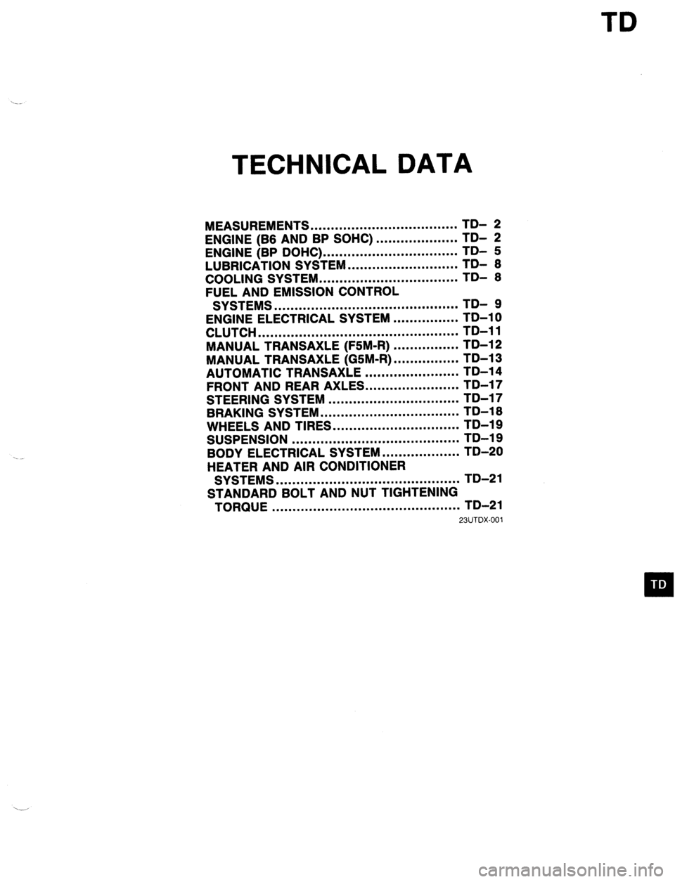
TD
TECHNICAL DATA
MEASUREMENTS .................................... TD- 2
ENGINE (B6 AND BP SOHC)
ENGINE (BP DOHC) ... .................................................. ;;- f
LUBRICATION SYSTEM ........................... TDI 6
COOLING SYSTEM .................................. TD- 6
FUEL AND EMISSION CONTROL
SYSTEMS ............................................. TD- 9
ENGINE ELECTRICAL SYSTEM ................ TD-10
CLUTCH ................................................. TD-11
MANUAL TRANSAXLE (F5M-R) ................ TD-12
MANUAL TRANSAXLE (GSM-R) ................ TD-13
AUTOMATIC TRANSAXLE ....................... TD-14
FRONT AND REAR AXLES.. .....................
STEERING SYSTEM ................................ ;;-;;
-
BRAKING SYSTEM .................................. TD-16
WHEELS AND TIRES ............................... TD-19
SUSPENSION ......................................... TD-19
BODY ELECTRICAL SYSTEM ................... TD-20
HEATER AND AIR CONDITIONER
SYSTEMS ............................................. TD-21
STANDARD BOLT AND NUT TIGHTENING
TORQUE .............................................. TD-21
23UTDX-001
Page 1031 of 1164

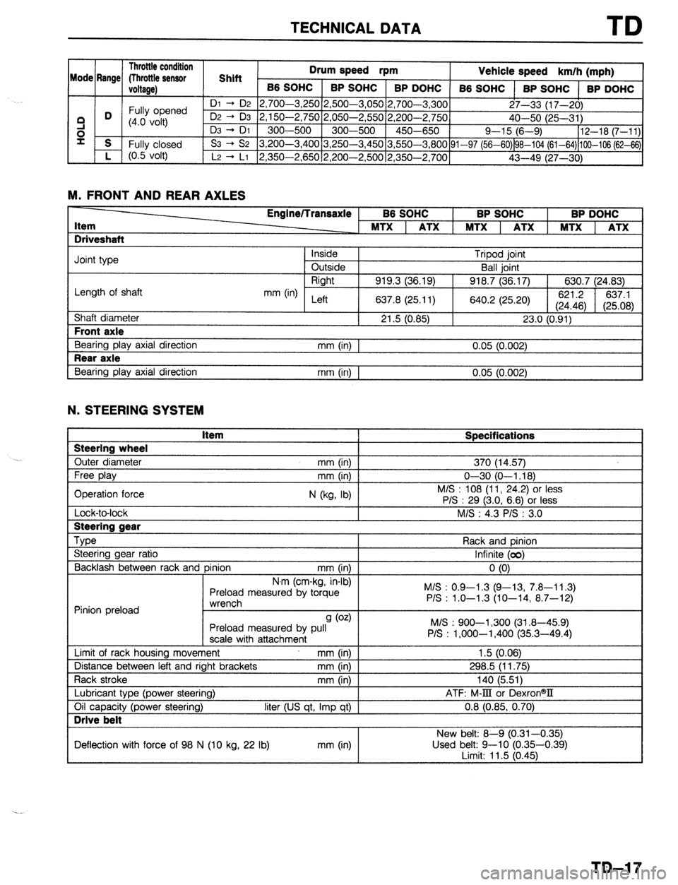
TECHNICAL DATA TD
1 Throttle condition 1
nrllm pn-t
Mode Rr _ me/ flhrottle sensor 1 Shift 1 -.- -*r2d rpm
Vehicle speed I km/h (mohl , . ,
I
ioltage) 1 B6 sot
iC 1 BP SOHC 1 BP DOHC
66 SOHC 1 BP SOHC 1 BP
I I I
’ ni - n9 I’) 7nn-1 “50 2,500-3,05012,700-3.3001 I I DOHC
Fully opened 27-33 (17-201
3 D (4.0 volt) 50 2,050-2,55012,200-2,750]
40-50 i25-31 j
e I 300-500 1 450-650 / Q-15 16-9) 112-18 (7-111
00 3,250-3,45013,550-3.800~91-97 f56-60&G10’4 (61-64)hOO-106;62-&\I
s
i- f Fully closed
(0.5 volt)
YI -l&c
L, r vv-“,L
Dz + D3 2,150-2,7
D3 -+ DI 300--5O(
S3 -+ S2 3,200-3,4
’ L2 -+ LI 2,350-2,65012,200-2,50012,350-2.7001
43-49 ;27--3b1 ’ ‘I
M. FRONT AND REAR AXLES -
Item
Driveshaft Engine/Transaxle BP SOHC BP DOHC
Joint type
Length of shaft
Shaft diameter Front axle
Bearing play axial direction Rear axle
Bearing play axial direction Inside Tripod joint
Outside Ball joint
Right
919.3 (36.19) 918.7 (36.17) 630.7 (24.83)
mm (in) Left
637.8 (25.11) 640.2 (25.20) 621.2
637.1
(24.46) (25.08)
21.5 (0.85) 23.0 (0.91)
mm (in) 1 0.05 (0.002)
mm (in) I 0.05 (0.002)
N. STEERING SYSTEM Steering wheel
Outer diameter Item Specifications 370 (14.57)
Lock-to-lock I Steering gear
--
Type
Steering gear ratio
Backlash between rack and pinion mm (in)
N.r ’ ’ ” ’ n (cm-Kg, in-01
Preload measured by torque
*rrv~rrdl Rack and pinion
Infinite (00)
0 (0)
M/S : 0.9-l .3 (Q-13, 7.8-l 1.3)
P/S : 1.0-1.3 (10-14, 8.7-12)
Pinion preload ““l~jll~,,
9 (0.4
Preload measured by pull
scale with attachment
Limit of rack housing movement mm (in)
Distance between left and right brackets mm (in)
Rack stroke mm (in M/S : 900-l ,300 (31.8-45.9)
P/S : l,OOO-1,400 (35.3-49.4)
1.5 (0.06)
298.5 (11.75)
140 (5.511
Lubricant type (power steering)
Oil capacity (power steering) Drive belt
liter (US qt, Imp qt) I ATF: M-III or DexronW
0.8 (0.85, 0.70)
I New belt: 8-Q (0.31-0.35)
Deflection with force of 98 N (10 kg, 22 lb) mm (in) Used belt: 9-10 (0.35-0.39)
I imit: 11.5 (0.461
TD-17