1992 MAZDA PROTEGE maintenance
[x] Cancel search: maintenancePage 161 of 1164

ON-VEHICLE MAINTENANCE
Drive plate (ATX)
1. Hold the drive plate with the SST or equivalent.
2. Remove the drive plate lock bolts.
3. Remove the backing plate, drive plate, and adapter.
2311082-052
I
Oil seal
1. Cut the oil seal lip with a razor knife.
2. Remove the oil seal with a screwdriver protected with a rag.
I I
I
05UOBX-063
Installation note
Oil seal
1, Apply a small amount of clean engine oil to the lip of a new
oil seal.
2. Push the oil seal slightly in by hand.
OWOBX-069
APPLY SEALANT
03UOB2.04
Caution
l The oil seal must be tapped in untjl it is flush with
the edge of the rear cover.
3. Tap the oil seal in evenly with a suitable pipe and a hammer.
Oil seal outer diameter: 1OOmm (3.94 in)
Flywheel (MTX)
1. Remove the sealant from the flywheel bolt holes in the crank-
shaft and from the flywheel bolts.
Caution
l If all the previous sealant cannot be removed from
a bolt, replace the bolt.
l Do not apply sealant if a new bolt is used.
2. Set the flywheel onto the crankshaft.
3. Apply sealant to the flywheel bolts and install them.
4. Hold the flywheel with the
SST or equivalent.
5. Tighten the bolts in two or three steps in the order shown
in the figure.
Tightening torque:
1 96-103 N-m (9.6-10.5 m-kg, 71-76 ft-lb)
2311082-053
B2--29
Page 162 of 1164

B2 ON-VEHICLE MAINTENANCE
0311082-04
23UOB2-05 4
Drive plate (ATX)
1. Remove the sealant from the drive plate holes in the crank-
shaft and from the drive plate lock bolts.
Caution
..i
l if ail the previous sealant cannot be removed from
a bolt, replace the bolt.
l Do not apply sealant if a new bolt is used.
2. Set the adapter, drive plate, and backing plate onto the
crankshaft,
3. Apply sealant to the drive plate bolts and install them.
4. Hold the drive plate with the
SST or equivalent.
5. Tighten the bolts in two or three steps in the order shown
in the figure.
Tightening torque:
96-103 N-m (9.6-10.6 m-kg, 71-76 ft-lb)
Steps After installation
1. Connect the negative battery cable.
2. Start the engine and perform engine adjustments as necessary.
OWOBX-072
82-30
Page 390 of 1164

F FUEL SYSTEM
MIN. 35mm (1..4 in) -/
23UOFX-10
NJ
23UOFX-l(
OBUOFX-1:
Installation Note
Fuel hoses
1. Push the ends of the main fuel hose, fuel return hose, and
evaporative hoses onto the fuel tank fittings at least 25mm
(1.0 in).
2. Push the fuel filler hose onto the fuel tank pipe and filler pipe
at least 35mm (1.4 in).
FUEL FILTER
Replacement
Low-pressure side (In-tank filter)
(Refer to page F-128.)
High-pressure side
The fuel filter must be replaced at the intervals outlined in the
maintenance schedule.
Warning
l Always work away from sparks or open flames.
1. Disconnect the fuel hoses from the fuel filter.
2. Remove the fuel filter and bracket.
3. Install in the reverse order of removal.
Note
l When installing the filter, push the fuel hoses fully
onto the fuel filter.
F-l 24
Page 449 of 1164

CHARGING SYSTEM G
RUB
PRO
03UOGX-01
Terminal and cable
1. Check the tightness of the terminals to ensure good electri-
cal connections.
2. Check for corroded or frayed battery cables.
3. Check the rubber protector on the positive terminal for prop-
er coverage.
4. Clean the terminals if necessary, and coat them with grease.
Recharging
Battery
55D23L Slow charge Quick charge
(A) (4
Under 6 Max. 20
Slow charging
It is not necessary to remove the vent caps to perform a slow
charge.
Quick charging
Remove the battery from the vehicle and remove the vent caps
to perform a quick charge.
Warning
l Before performing maintenance or recharging the
battery, turn off all accessories and stop the engine.
l The negative cable must be removed first and in-
stalled last.
l Set the battery in water when quick charging to pre-
vent overheating the battery.
G-9
Page 1016 of 1164

TD TECHNICAL DATA
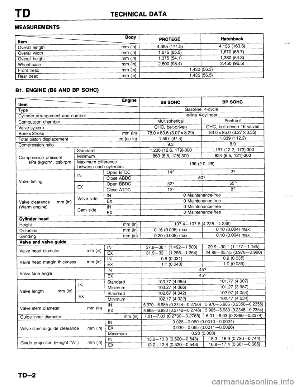
MEASUREMENTS
I ._.____2_ nem
Overall length
Overall width
Overall height
Wheel base
Front tread
Rear tread Body ) mm (in)
mm (in)
mm (in)
mm (in)
mm (in)
mm (in) PRfWFr.f! . . ..s .-VW Hatchback 4,355 (171.5) 4,155 (163.6)
1,675 (65.9) 1,670 (65.7)
1,375 (54.1) 1,380 (54.3)
2,500 (98.4) 2,450 (96.5)
1,430 (56.3)
1,435 (56.5)
Bl. ENGINE (B6 AND BP SOHC)
1 Type
1 Cylinder arrangement and number Engine
86 SOHC BP SOHC
^ . . _
,?
I
uasollne, 4-cyw
. . *. 4
in-line 4-cyrinaer
Pentroof
1
I Combustion chamber I Multispherical
J Valve system OHC, belt-driven OHC, belt-driven 16 valves
. , I (3.07 x 3.29) 83.0 x 85.0 (3.27 x 3.35)
Total piston displacement cc (cu in) 1,597 (97.4) 1,839 (112.2)
Compression ratio 9.3 8.9
) Standard 1,236 (12.6, 179)-300 1,197 (12.2, 173)300
I
863 (8.8, 125)-300 834 (8.5, 121)300 1 Bore x Stroke
mm (in) I 78.0 x 83.6
Compression pressure
kPa (kg/cm’, psi)-rpm
E cvlinders 1 Maximum difference
196 (2.0, 28)
I
, ------- ---- -J - IN Open BTDC 14O 2O
Close ABDC 50°
Valve timing
Open BBDC 52O 55O
EX
Close ATDC 12O 8O
IN 0 Maintenance-free I \/AIo &-in --
Valve clearance EX 0 Maintenance-free
(Warm engine) mm (in) / ,,syi: 1
IN 0 Maintenance-free
I , EX 0 Maintenance-free
I Cylinder head
Height
Distortion
Grinding Valve and T _
Valve head diameter
Valve head margin thickness
Valve face angle IN mm (in) EX
IN
mm b-4 Fx mm (in) 107.4-107.6 (4.228-4.236)
mm (in) 0.15 (0.006) max. 0.10 (0.004) max.
mm (in) 0.20 (0.008) max. 0.10 (0.004) max.
37.9-38.1 (1.492-l ,500) 29.9-30.1 (1.177-1.185)
31 .Q-32.1 (1.256-l ,264) 24.85-25.15 (0.978-0.990)
0.8 (0.031) 0.9 (0.035)
1.1 10.043) 1 .o (0.039)
-, ,
\- I
IN 45O
EX 45O
I I Standard
IN
Minimum
Valve length mm (in)
EX Standard
Minimum I”L. I, \*.“cL
Valve stem diameter IN
mm On) EX 6.970-6.985 (0.2744-
6.965-6.980 (0.2742-
Guide inner diameter
I Valve stem-to-guide clearance mm (in) lTj7---- ,
Maximum 103.77 (4,085) 101.77 (4.007)
103.27 (4.066) 101.27 (3.987)
102.67 (4.042) 102.97 (4.054)
,n+ 47 IA noo
1 102.47 (4.034)
-0.2750) 5.970-5.985 (0.2350-0.2356)
-0.2748) 5.965-5.980 (0.2348-0.2354)
3.2760-0.2768) 6.01-6.03 (0.2366-0.2374)
0.025-0.060 (0.001 O-0.0024)
0.030-0.065 (0.001 l-0.0026)
-.
I
mm (in) 1 7.01-7.03 (r ‘
1 IN
Guide projection (Height “A”) IN
mm (in) Ex 13.2-l 3.8 (0.520-
13.2-13.8 (0.520-
TD-2
Page 1019 of 1164

TECHNICAL DATA TD
r-
RP sm.lc: I Item
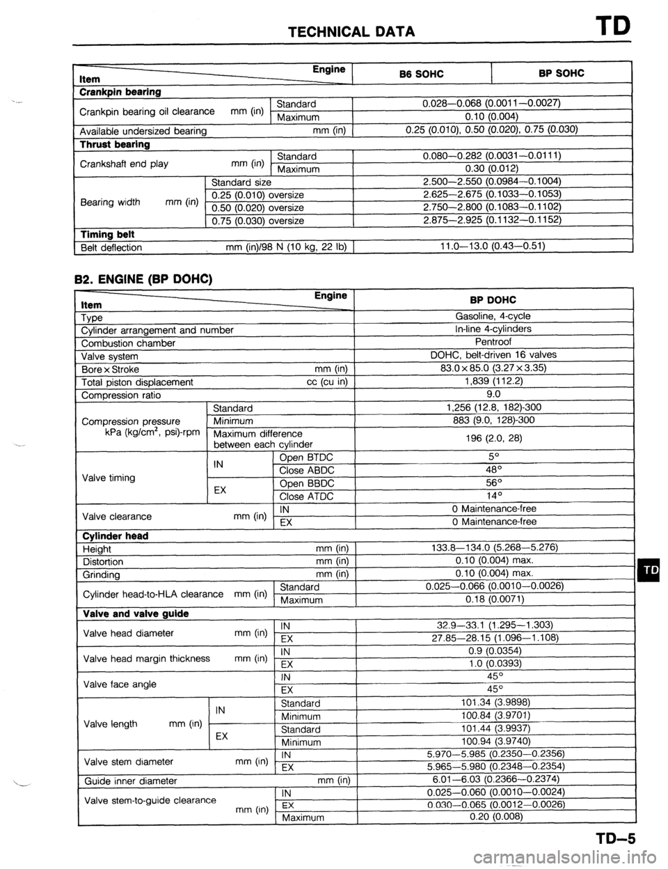
Crankpin bearing Engine
86 SOHC
I -. VW.._
Crankpin bearing oil clearance mm (in) Standard 0.028-0.068 (0.001 l-0.0027)
Maximum 0.10 (0.004)
Available undersized bearing mm (in)
0.25 (O.OlO), 0.50 (0.020) 0.75 (0.030) Thrust bearing
Crankshaft end play mm (in) Standard 0.080-0.282 (0.0031-0.0111)
Maximum 0.30 (0.012)
Standard size 2.500-2.550 (0.0984-0.1004)
Bearing width mm (in) 0.25 (0.010) oversize 2.625-2.675 (0.1033-0.1053)
0.50 (0.020) oversize 2.750-2.800 (0.1083-0.1102)
0.75 (0.030) oversize 2.875-2.925 (0.1132-0.1152)
1 Timing belt
Belt deflection mm (in)/98 N (10 kg, 22 lb) 1 11 .o-13.0 (0.43-0.51) 82.
ENGINE (BP DOHC) Item
Type
Cylinder arrangement and number BP DOHC
Gasoline, 4-cycle
In-line 4-cylinders
-. I
Combustion chamber
Valve svstem DOHC, belt-d
Bore x Stroke
Total piston displacement ventroot
riven
(3.2:
mm (in) 1 83.0 x 85.0
cc (cu in) ]
7x3.35)1 1,839 (112.2)
I 16 valves I 9.0
-300
mn Compression ratio
Standard 1,256 (12.8, 182)
Compression pressure Minimum 883 (9.0, 128)-Z kPa (kglcm2,
Psi)-rPm
Maximum dif
‘ference
between eat -, h cvlinder 196 (2.0, 28)
IN Open BTDC 5O
Valve timing Close ABDC 48’
EX Open BBDC 56O
Close ATDC .4 In
IY-
IN
mm (in) EX 0 Maintenance-l
Valve clearance
0 Maintenance-i ‘ree
‘me Cylinder head
Height mm (in)
Distortion mm (in)
Grinding mm (in)
Standard
Cylinder head-to-HLA clearance mm (in) Maximum Valve and valve guide 133.8-134.0 (5.268-5.276)
0.10 (0.004) max.
0.10 (0.004) max.
0.025-0.066 (0.0010-0.0026)
0.18 (0.0071)
Valve head diameter IN
mm (in) EX 32.9-33,l (1.295-l ,303)
27.85-28.15 (1.096-1.108)
Valve head margin thickness IN
mm On) Fx 0.9 (0.0354)
1 .o fO.0393)
1 Valve face angle . .
I
FX I I
Valve length IN
Standard 101.34 (3.9898)
mm (in) Minimum 100.84 (3.9701)
Standard 101.44 (3.9937) I -, .
I
Valve stem diameter EX
Minimum loo.94 i3.974oj
IN
mm (in) - EX 5.970-5.985 (0.2350-0.2356)
5.965-5.980 (0.2348-0.2354)
mm (in) I
. , , 6.01-6.03 (0.23 166-0.2374)
1 IN
I 0.025-0.060 (0.0010-0.0024)
3.0012-0.0026)
( Maximum 0.20 (0.008)
I
TD-5
Page 1067 of 1164

Troubleshootina Z-GM 1
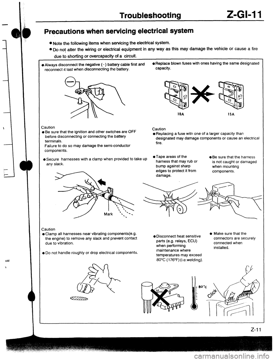
Precautions when servicing electrical system
l Note the following items when servicing the electrical system.
l Do not alter the wiring or electrical equipment in any way as this may damage the vehicle or cause a fire
due to shorting or overcapacity of a circuit.
l Always disconnect the negative (- ) battery cable first and 0 Replace blown fuses with ones having the same designated
reconnect It last when disconnecting the battery. capacity.
1OA
15A
Zaution
l Be sure that the ignition and other switches are OFF
before disconnecting or connecting the battery
terminals.
Failure to do so may damage the semi-conductor
components. Caution l Replacing a fuse with one of a larger capacity than
designated may damage components or cause an electrical
fire.
l Secure harnesses with a clamp when provided to take Up l Tape areas of the
a Be sure that the harness
any slack. harness that may rub or
is not caught or damaged
bump against sharp
when mounting
edges to protect it from
components.
damage.
Caution
l Clamp all harnesses near vibrating components(e.g.
the engine) to remove any slack and prevent Contact
due to vibration.
l Do not handle roughly or drop electrical components.
l Disconnect heat sensitive
parts (e.g. relays, ECU)
when performing
maintenance where
temperatures may exceed l Make sure that the
connectors are securely
connected when
installed.
80°C (176°F) (i.e.welding).
oid