1992 MAZDA PROTEGE lights
[x] Cancel search: lightsPage 895 of 1164

EXTERIOR LIGHTING SYSTEM T
Stoplight
Circuit diaaram
GTOPLIGHTS F-2
SHIFT-LOCK
BLUB TRADE NUMBER
STOPLIGHT: 1157 (27W)
HIGH MOUNT
STOPLIGHT: 921 (18.4W) G (F) *ENGINE CONTROL UNIT
(SECTION B- lc;26)
G (F) *CRUISE CONTROL UNIT
(SECTION 01)
WITH REAR SPOILER
HIGH MOUNl-
STOPLIGHT
STOPLIGHT STOPLIGHT
-06 STOPLIGHT
SWITCH (F) F-07 HIGH MOUNT STOP-E-12 STOPLIGHT LH(R) E-13 STOPLIGHT RH(R)
LIGHT (R3)
WITH
REAR SPOILER---+ (R2)
03UOTX-057
T-39
Page 896 of 1164

I
EXTERIOR LIGHTING SYSTEM
Both stoplights do not operate when brake pedal is
depressed
i
Check stop 20A fuse
I Short circuit
Confirm battery voltage on G/W wire of the stoplight
switch
I Repair harness (Fuse - Stoplight switch) OK
Check the voltage with the brake pedal depressed
I
BD
c
Confirm battery voltage on G Replace the stoplight switch
8) OK
Confirm battery voltage on G Repair harness (Stoplight switch - Stoplight)
(B
Confirm continuity on B wir Repair harness (Stoplight - Body ground)
I I I
I
Replace the bulb
I
23UOTX-023 One stoplight does not come on
Burnt out bulb or faulty grounding
03UOTX-058
T-40
Page 1055 of 1164
Z
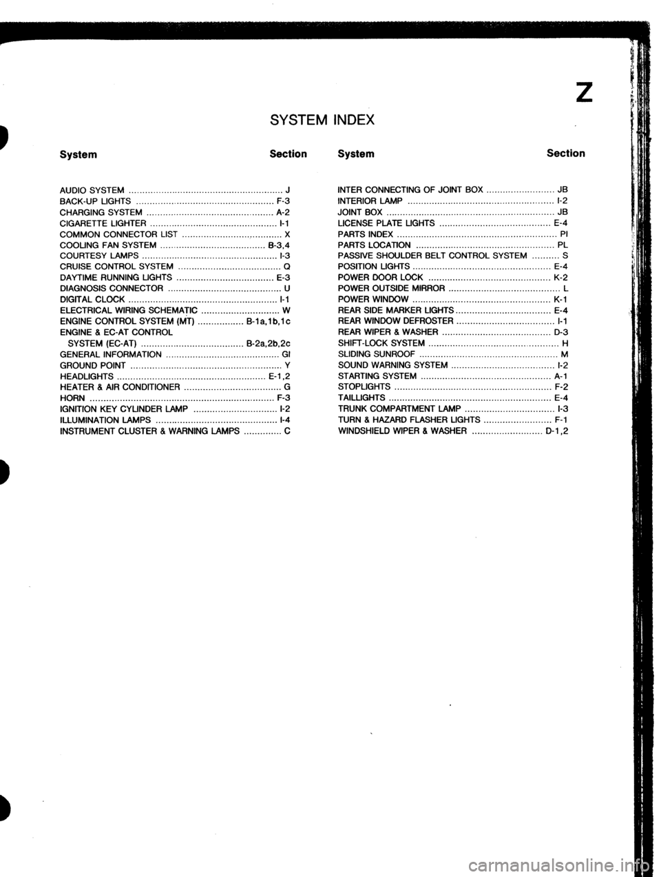
SYSTEM INDEX
System Section System Section
AUDIO SYSTEM ......................................................... J
BACK-UP LIGHTS ...................................................
F-3
CHARGING SYSTEM ............................................... A-2
CIGARETTE LIGHTER ............................................... I-1
COMMON CONNECTOR LIST ..................................... X
COOLING FAN SYSTEM ....................................... B-3.4
COURTESY LAMPS .................................................. l-3
CRUISE CONTROL SYSTEM ...................................... Q
DAYTIME RUNNING UGHTS .................................... E-3
DIAGNOSIS CONNECTOR .......................................... U
DIGITAL CLOCK ....................................................... l-l
ELECTRICAL WIRING SCHEMATIC ............................. W
ENGINE CONTROL SYSTEM (MT) ................. B-l a, 1 b, 1 c
ENGINE 8 EC-AT CONTROL
SYSTEM (EC-AT) ...................................... B-2a,2b,2c
GENERAL INFORMATION .......................................... GI
GROUND POINT ........................................................ Y
HEADLIGHTS ....................................................... E-l ,2
HEATER 8 AIR CONDITIONER .................................... G
HORN .................................................................... F-3
IGNITION KEY CYLINDER LAMP ............................... l-2
ILLUMINATION LAMPS .............................................
l-4
INSTRUMENT CLUSTER . WARNING LAMPS .............. C INTER CONNECTING OF JOINT BOX ......................... JB
INTERIOR LAMP ...................................................... l-2
JOINT BOX .............................................................. JB
LICENSE PLATE UGHTS ......................................... E-4
PARTS INDEX ........................................................... PI
PARTS LOCATION ................................................... PL
PASSIVE SHOULDER BELT CONTROL SYSTEM .......... S
POSITION LIGHTS ................................................... E-4
POWER DOOR LOCK ............................................. K-2
POWER OUTSIDE MIRROR ......................................... L
POWER WINDOW ................................................... K-l
REAR SIDE MARKER LIGHTS.. ................................. E-4
REAR WINDOW DEFROSTER .................................... I-1
REAR WIPER 8 WASHER ........................................ D-3
SHIFT-LOCK SYSTEM ................................................ H
SLIDING SUNROOF ................................................... M
SOUND WARNING SYSTEM ...................................... l-2
STARTING SYSTEM ................................................ A-l
STOPLIGHTS .......................................................... F-2
TAILLIGHTS ............................................................ E-4
TRUNK COMPARTMENT LAMP ................................. l-3
TURN 8 HAZARD FLASHER UGHTS ......................... F-l
WINDSHIELD WIPER 8 WASHER .......................... D-l ,2
Page 1065 of 1164
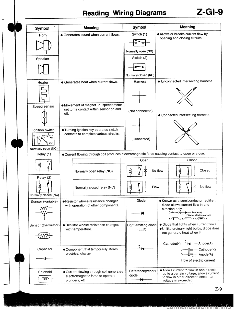
Reading Wiring Diagrams Z-GI-9
Symbol ‘ Meaning Symbol Meaning
Horn l Generates sound when current flows. Switch (1) l Allows or breaks current flow by
opening and closing circuits.
Speaker
w
Heater l Generates heat when current flows. Normally open (NO)
Switch (2)
Normally closed (NC)
Harness l Unconnected intersecting harness.
Speed sensor l Movement of magnet in speedometer
set turns contact within sensor on and
Off. (Not connected)
l Connected intersecting harness.
Ignition switch @Turning ignition key operates switch
contacts to complete various circuits.
(Connected)
rlormally open (NO)
Relay (1) l Current flowing through coil produces electromagnetic force causing contact to open or close.
____- .~.~~
Open Closed
--.--.-m.---------,
Relay (2) Normally open relay (NO)
- Ri i No flow ’ ni 1 Closed
Normally closed relay (NC) Flow
ormally closed (NC)
Sensor (variable) l Resistor whose resistance changes Diode
l Known as a semiconductor rectifier.
--3p6G- with operation of other components. diode allows current flow in one
direction only
--T- IA
IY Calhode(K)+- Anode(A)
* Flow of electric current
K-1 KD, he>:
-
ensor (thermistor)
l Resistor whose resistance changes Light emitting diode 0 Diode that lights when current flows
with temperature.
(LED)
l Unlike ordinary light bulbs, diode does
not generate heat when lit
Capacitor
l Component that temporarily stores “2, Cathode(K) --&---Anode(A)
I7
Cathode(K)
electrical charge.
c Anode(A)
----il---- .
Flow of electric current
Solenoid
l Current flowing through co11 generates Reference(zener) l Allows current to flow In one dlrectlon
electromagnetic force to operate diode up to a certain voltage. allows current
plungers, etc. cd to flow In other dIrectron once that
J-
voltage IS exceeded.
z-9
Page 1072 of 1164
II-GM6 Troubleshooting
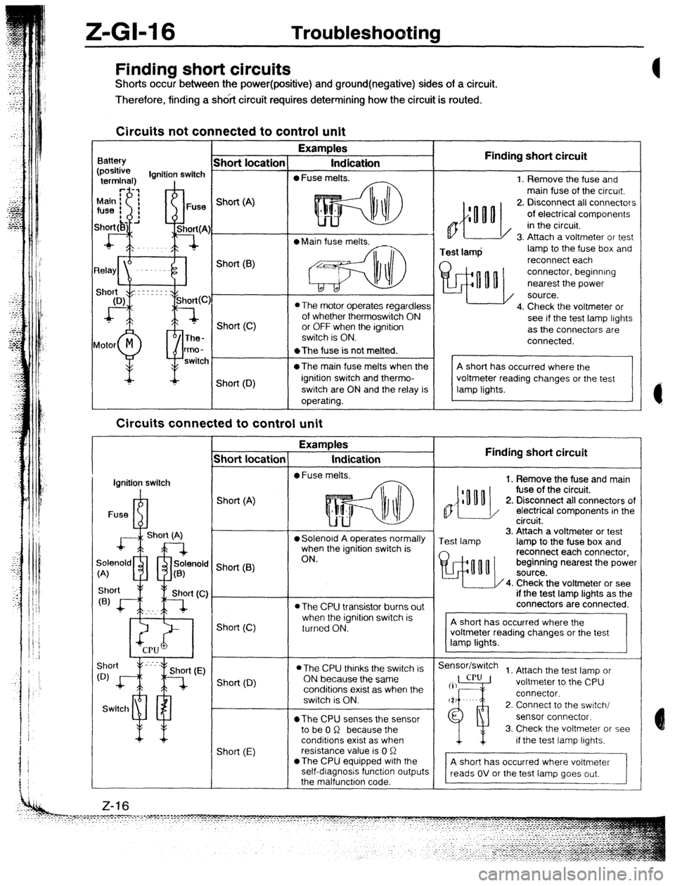
Finding short circuits
Shorts occur between the power(positive) and ground(negative) sides of a circuit.
Therefore, finding a shdit circuit requires determining how the circuit is routed.
Circuits not connected to control unit
Examples
Indication
0 Fuse melts. Finding short circuit
0
Test lamp 1. Remove the fuse and
main fuse of the circurt.
2. Disconnect all connectors
of electrical components
in the circuit.
3. Attach a voltmeter or test
lamp to the fuse box and
reconnect each
connector, beginning
nearest the power
source.
4. Check the voltmeter or
see if the test lamp lights
as the connectors are
connected. Finding short circuit
,,{:““o
1. Remove the fuse and main
fuse of the circuit.
2. Disconnect all connectors of
/ electrical components in the
circuit.
Test lamp 3. Attach a voltmeter or test
lamp to the fuse box and
reconnect each connector,
beginning nearest the power
4. Check the voltmeter or see
if the test lamp lights as the
connectors are connected.
Sensor/switch
1. Attach the test lamp or
voltmeter to the CPU
connector.
2. Connect to the swrtch/
sensor connector.
3. Check the voltmeter or see
if the test lamp lights.
A short has occurred where voltmeter
reads OV or the test lamp goes out,
- Short location
Battery Short (A)
l Main fuse melts.
L* Short(B)
0 The motor operates regardless
of whether thermoswitch ON
or OFF when the ignition
switch is ON. Short (C)
lotor
M
P The-
tmo-
switc *The fuse is not melted.
@The main fuse melts when the
ignition switch and thermo-
switch are ON and the relay is
operating. Short (D)
Circuits connected to control unit
-T Examples
Indication
l Fuse melts.
- Short locatior
I
ignition switch
I
Fuse R-l Short (A)
J+L--l
Short (A) l Solenoid A operates normally
when the ignition switch is
ON.
9enold m rfr solenok
;<
A) u a(B) ’ Short (6)
l The CPU transistor burns out
when the ignition switch is
turned ON. Short (C)
l The CPU thinks the switch is
ON because the same
conditions exist as when the
switch is ON.
*The CPU senses the sensor
to be 0 R because the
conditions exist as when
resistance value is 0 R
*The CPU equipped with the
self-diagnosis function output
the malfunctron code. Short (0)
Swltcl1 ml
Short (E) Z-16
Page 1077 of 1164
WIRINQ DIAQRAM 2
-CURRENT FROM BATTERY
W II f”‘l FCTRICAL WIRING SCHEMATIC _1_=;!:: %% :% I’*
BATTERY
P-
f
30A HEAD SYSTEM NAME
-a
c------
15A TAIL I
t-
BOA
MAIN
7 ST /;
(i
IG
:
:
1
:
I
20A ?--
AD FAN
_-. --
VW/B : I
I
I
I TRUNK COMPARTMENT
l LAMP I-3
:
I ( - n COURTESY LAMPS I-3
I
1OA
3EAR WIPER I
-- ---- L,G--/-~~-.=/zzI~~~
l REAR WIPER 6 WASHER D-3
20A WIPER
30A HEATER
,-w ---- L,w-l;c::::
I
INSTRUMENT CLUSTER
l & WARNING LAMPS C
15A METER
-----+yy _---
IOA ROOM
-1
t
----------.mBUCK-UP LIGHTS F-3
20A STOP
-G/W i - m HORN F-3
1
I
F-2
/--------%CRUISE CONTROL SYSTEM 0
. l SHIFT-LOCK SYSTEM
15A
HAZARD
I-- ------. H
--- _------
TURN 6 HAZARD
--o----B/R ; n FLASHER LIGHTS F-l
I
IPOWER DOOR LOCK K-;
’ PASSIVE SHOULDER BELT s
-mCONTROL SYSTEM
+-B/R--+-/ “Yr. I YV.LI, T.AI1a.A
---------B/W----~-i-t------. n P,-&,ER WINDOW
K-l
I
1
I I 15A ENGINE
- - I
:-,-..-L ----.- T -------- B,wl--‘-
; 30A FUEL INJ ’ a...
I- W/G ’ --------.=ENGINE CONTROL SYSTEM y-2
t ----------e--e-_ I--- ---_ .w-.w-.m-.
I
I t
: I 0
WDIGITAL CLOCK I-l
,
I 20A DEFOG I r-- WINDOW DEFROSTER 1-1
B/L I -- mCIGARETTE LIGHTER I-l
:
_ mAU’)IO SYSTEM
i----a,w-.--15A RAo1o -.-L,e-i~---i--mPOWER J
OUTSIDE MIRRIOR L
30A COOLING FAN L- ------------.
l COOLING FAN SYSTEM ;-4
B/R-p-
l STARTING SYSTEM A-l
Page 1088 of 1164
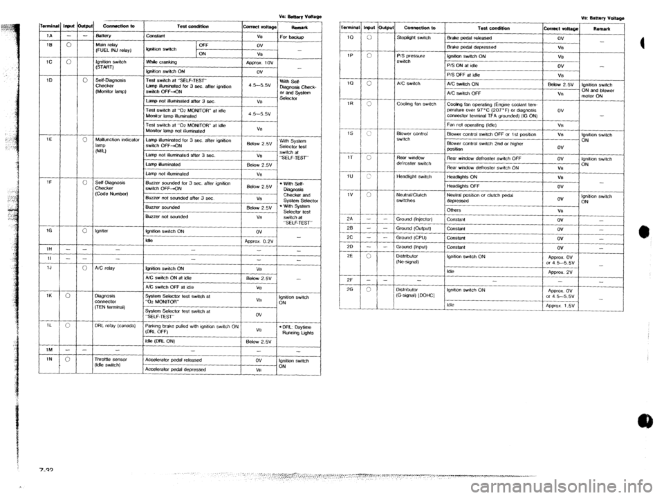
T.&condition
-t
Off
IQ”&” switch
ON
Whik cranking
lgnitlon switch ON
Test switch at “SELF-TEST”
Lamp illuminated for 3 sec. after ignition
SwiIch OFF-KIN
Lamp not illuminated after 3 sec. collect vdtaQe
ReRlar*
ve
For backup
ov
-
V%
Approx. tov
ov
4 5--5.5v With Self-
D&Q”& Check-
er and system
Vi3 st?lt?ctor Input &PJ
- -
0
0
0
0
0
0
- -
- -
0
0
c
- -
0 connectkfl to mnina
Connection to
Stoplight swtch Test condition
-L 1A
Bake pedal released
IEI
IC Main relay
(FUEL INJ relay) Brake pedal depressed
lQ”ih0” switch ON
___-- P/S Qrc?ss"re
switch
Ignition switch
(START) P/S ON at idle
P/S OFF at idle
A/C switch ON
A/C switch OFF
Cwlng fan operatng (Engine coolant tem-
perature over 97°C (207°F) or dlagnosls
connector terminal TFA grounded) (IG ON)
Fan not ooeralmg (Idle) 1D .self-mag”osls
Checker
(Monitor lamp) A!C switch
coohng fan swtctl
Test switch at “02 MONITOR” at idle
Monitor lamp ilfummated
Test switch at “02 MONITOR” at idle
Monitor lamp not illuminated
Lamp illuminated for 3 sec. after ignition
switch OFF&N
Lamp not illuminated after 3 ser.
Lamp illuminated
Lamp not #lluminated VB
Below 2.w With System
Selector test
VB swtch at
“SELF-TEST”
Eelow 2.5v
VS Blower Control
swttch Blower control switch OFF or 1 st posihon
Blower control swtch 2nd or htgher
position 1E
Malfunction indicator
lamp
NJ
Rear window defroster swtch OFF Rear wmdow
defroster switch
Headkght switch Rear window defroster Switch ON
-2-A - I
tieadlghts ON
Headlights OFF
Neutral positton or clutch pedal
depressed
OlhWS l Wiih Self-
DkQnosls
Checker and
Svstem Selector Self- Diaanosis Buzzer sounded for 3 sec. after ignition
switch OFF-ON
Buzzer not sounded after 3 set 6&w 2.5v
V8 Checke;
(Cede Number) I
ov Ignition swtch
ON NeulraliClutch
switches
. ‘.&h System
Selector test
switch at Buzzer sou”ded
1 Below 2.5V 1
VB
ov -
ov -
ov -
ov -
APprox. ov
or 4 5-5 5v
-
Approx. 2V
-
-
AQWOX. Ov
or 4 5-5 5v
-
APQ~OX 1.5V Buzzer not sounded
I VE
I
Ground (Injector)
Ground
(OUtQUt)
Ground (CPU)
Grou”d (Input)
constant
lgnlti swtch ON
klk “SELF-TEST”
ov
-
Ap~rox O.2V
- - Constant
Co”stant lgnller
1H
Constant
Igntho” swdch ON -
- D&ribulor
(Ne-sIgnal) II
1J
1K
1L
1M
1N -
fgnition switch ON
AX switch ON al idle
NC switch OFF at Idle
System Selector lest switch at
“0-z MONITOR” I -
- VB
5&w 2.w -
Vi3
VB Ignition switch
ON
System Selector test swatch at
“SELF-TEST”
ParkIng brake pulled wth lgndlon swtch ON
(DRL OFF) ov
VB
l DRL: oaytime Running tigms
Idle (DFtL ON) Below 2.5v A/C relay
Idle
-
Ignition swtch ON
-
Distributor
(G-stgnal) [DOHC]
3ignosis
x”“ec1or
,TEN terminal) Idle
3RL relay (canada)
-
Accelerator pedal released
Accelerafor pedal depressed
-
ov
VB
-
Ignition switch
ON rhr0ttte sensor
‘Idle switch)
Page 1094 of 1164
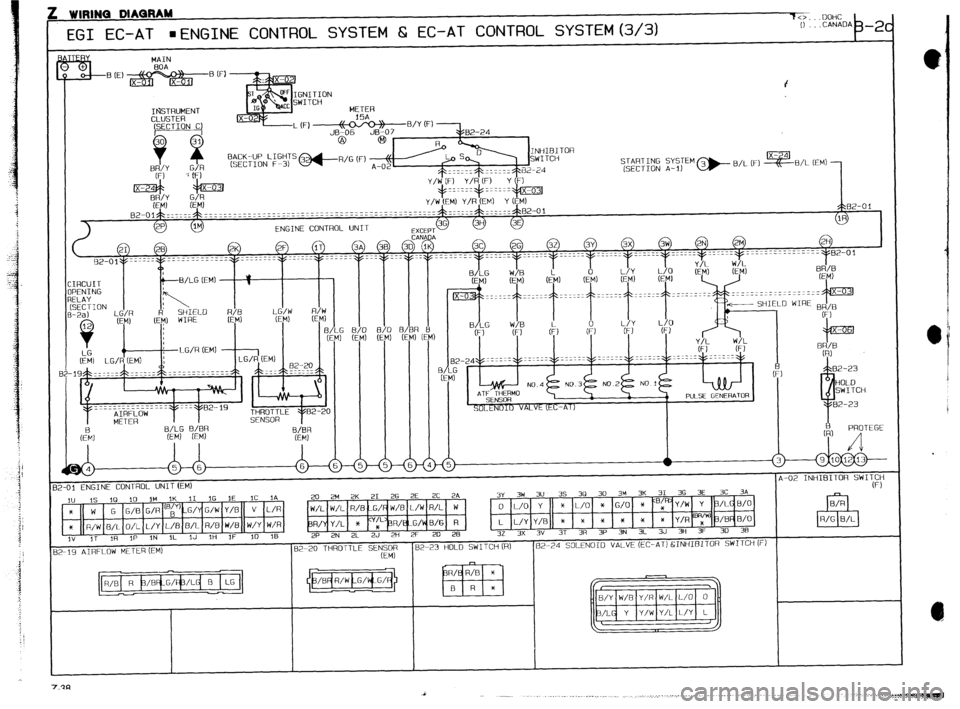
: WIRINQ MAQRAM
70...UOHC
EGI EC-AT
aENGINE CONTROL SYSTEM Cz EC-AT CONTROL SYSTEM(3/3) 0 -CANADA
b -2c
MAIN
%,E,$$$?@&?%(F,
4
GNITION
WITCH
IGSTRUMENT METER
CLUSTER 15A
BACK-UP LIGHTS
(SECTION F-3)
~~~~$~ z,s:EM @-- B/L (F) -0lL (EMi -
5>82-0 1
2P IM
ENGINE CONTROL UNIT 3G 3H
3E IR
:EPT
21 28 2K 2F IT (
Y2-01~==----~-------------~--‘---‘-~~-----~------
B/LG %/%R
(EM) IEM)
1
E/;
:
6 3A
?
‘-01 ENGINE CONTROL UNITfEM) A-02 INHIBITOR SWI!$y
III 1s 10 10 1M IKm 3 IG IE 1C IA 20 2M
2K 21
26 2E 2C
2A
*
W G G/B G/R (Bc) G/ G/W
x llWWlR/I In/LJL/YIL/B B/L R/B
i
3~ 3~ 3” 35 3~ 30 34 3K 31 36 3E 3C
3A
0 L/O Y X L/O * G/O * /L e/o
L L/Y Y/B * * * * * * Y/R @y’ /% a/o
IN 3F 30 38 1 1 ’ I 5 1 n *a
. .
. .
I .’ II’ “‘l-‘-l-’ -I-. 1
’ ’ ’ ” ’ ’ I . . *...
iv ,T ,R IP IN iL IJ ,ti 1F 10 IB 2P 2N 2~ 2J 2H 2F 20 28 32 3X 3”
3T 3A 3P 3N 3L 33 3
1-19 AIRFLOW METER (EM) 82-20 THROTTLE SE+Op 182-23 HOLD SWITCH&+
ttM1 1 162-24 SOLENOID VALVE (EC-AT) &INHIBITOR SWITCH iF)
I
A
__ .._..... -. .._ __._. _ __..... .., .___....__.._ __.. _..~ . . .._...., . . . .