1992 MAZDA PROTEGE height
[x] Cancel search: heightPage 815 of 1164

REAR WIPER AND WASHER S
Wiper
Washer
1. Rear hatch lower trim
7. Trunk end trim
Removal / Installation . . . . . . . . . . . . . . . . page S-
98 Removal / Installation . . . . . . . . . . . . . . . . page
S- 98
2. Wiper arm cover 8. Trunk side cover
3. Rear wiper arm and blade Removal / Installation . . . . . . . . . . . . . . . . page S-
98
Adjustment
Note . . . . . . . . . . . . . . . . . . . . . . . page S- 79 9. Trunk side trim
4. Seal cap Removal / Installation . . . . . . . . . . . . . . . . page S-
98
5. Outer bushing 10. Rear header trim
6. Rear wiper motor Removal / Installation . . . . . . . . . . . . . . . . page S- 98
Inspection .,, ., . . . . . . . . . . . . . . . . . . . . . . . . . . . .
page S- 77 11. Rear seat belt upper anchor
Removal / Installation . . . . . . . . . . . . . . . . page S-l 01
12. C-pillar trim
Removal / Installation . . . . . . . . . . . . . . . . page S-
98
13. Washer tank assembly
a. Washer tank
b. Washer motor
Inspection . . . . . . . . . . . . . . . . . . . . . . . . . . . . . . . . .
page S- 77
14. Washer nozzle
Adjustment Note . . . . . . . . . . . . . . . . . . . . . . . page S-
79
15. Washer pipe
23UOSX-032
REAR WINDOW MOLDING
mm (in)
03uosx-14
REAR WINDQW MOLDING I
mm (in
03uosx-14
Adjustment Note
Arm height
1. Set the motor shaft to the park position by turning the rear
wiper switch from ON to OFF.
2. Set the arm height as shown in the figure.
Tightening torque:
5.9-9.8 N*m (80-100 cm-kg, 52-87 in-lb)
Washer nozzle
Inset-t a needle or similar object into the nozzle hole and move
the nozzle to adjust the spray direction.
s-79
Page 823 of 1164

SLIDING SUNROOF S
03UOSX-16d
(SUNROOF) (MOONROOF)
03UOSX-16!
ADJUSTING SCREW
SECA-A
D
__--__..-- ---__.-__
031JOSX 16
__-__
-~-
03UOSX-16
2. Install the guide rail cover and set plate.
3. Turn the motor using the emergency handle, and visually
check the sliding, tilt-down and tilt-up operations.
Adjustment Note
Sliding panel assembly
Height
Adjust so that the height difference between the sliding panel
and the roof panel is
1.5mm (0.06 in) max, referring to below.
(Front portion)
1. Loosen installation screws (1) and (2).
If the adjustment is only about
2mm (0.08 in) don’t loosen
screw (1).
2. Turn the screws to adjust.
Turning to the right raises; to the left lowers.
3. Tighten installation screws (1) and (2).
(Rear portion)
1. Loosen the adjusting screw.
2. Adjust by moving the sliding panel.
3. Tighten the adjusting screw.
S-987
Page 943 of 1164

CRUISE CONTROL SYSTEM T
OSUOTX-14
PEDAL HEIGHT
03UOTX-I 4’
OSUOTX-18
Actuator
Measure the actuator solenoid resistance using an ohmmeter.
Check terminals
c-a
c-b Resistance
Approx. 22 to 553
Clutch switch, Brake switch
When servicing these switches, adjust them so that the cor-
responding pedal height is as specified.
Pedal height (With carpet)
Clutch: 196-204mm (7.72--6.03 in)
Brake : 193-196mm (7.60-7.72 in)
Stoplight switch (For cruise)
Check that there is continuity between (P) and (V) wires when
the brake pedal is released.
T-87
Page 1016 of 1164
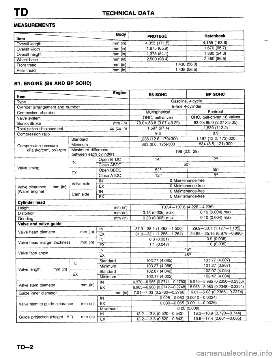
TD TECHNICAL DATA
MEASUREMENTS
I ._.____2_ nem
Overall length
Overall width
Overall height
Wheel base
Front tread
Rear tread Body ) mm (in)
mm (in)
mm (in)
mm (in)
mm (in)
mm (in) PRfWFr.f! . . ..s .-VW Hatchback 4,355 (171.5) 4,155 (163.6)
1,675 (65.9) 1,670 (65.7)
1,375 (54.1) 1,380 (54.3)
2,500 (98.4) 2,450 (96.5)
1,430 (56.3)
1,435 (56.5)
Bl. ENGINE (B6 AND BP SOHC)
1 Type
1 Cylinder arrangement and number Engine
86 SOHC BP SOHC
^ . . _
,?
I
uasollne, 4-cyw
. . *. 4
in-line 4-cyrinaer
Pentroof
1
I Combustion chamber I Multispherical
J Valve system OHC, belt-driven OHC, belt-driven 16 valves
. , I (3.07 x 3.29) 83.0 x 85.0 (3.27 x 3.35)
Total piston displacement cc (cu in) 1,597 (97.4) 1,839 (112.2)
Compression ratio 9.3 8.9
) Standard 1,236 (12.6, 179)-300 1,197 (12.2, 173)300
I
863 (8.8, 125)-300 834 (8.5, 121)300 1 Bore x Stroke
mm (in) I 78.0 x 83.6
Compression pressure
kPa (kg/cm’, psi)-rpm
E cvlinders 1 Maximum difference
196 (2.0, 28)
I
, ------- ---- -J - IN Open BTDC 14O 2O
Close ABDC 50°
Valve timing
Open BBDC 52O 55O
EX
Close ATDC 12O 8O
IN 0 Maintenance-free I \/AIo &-in --
Valve clearance EX 0 Maintenance-free
(Warm engine) mm (in) / ,,syi: 1
IN 0 Maintenance-free
I , EX 0 Maintenance-free
I Cylinder head
Height
Distortion
Grinding Valve and T _
Valve head diameter
Valve head margin thickness
Valve face angle IN mm (in) EX
IN
mm b-4 Fx mm (in) 107.4-107.6 (4.228-4.236)
mm (in) 0.15 (0.006) max. 0.10 (0.004) max.
mm (in) 0.20 (0.008) max. 0.10 (0.004) max.
37.9-38.1 (1.492-l ,500) 29.9-30.1 (1.177-1.185)
31 .Q-32.1 (1.256-l ,264) 24.85-25.15 (0.978-0.990)
0.8 (0.031) 0.9 (0.035)
1.1 10.043) 1 .o (0.039)
-, ,
\- I
IN 45O
EX 45O
I I Standard
IN
Minimum
Valve length mm (in)
EX Standard
Minimum I”L. I, \*.“cL
Valve stem diameter IN
mm On) EX 6.970-6.985 (0.2744-
6.965-6.980 (0.2742-
Guide inner diameter
I Valve stem-to-guide clearance mm (in) lTj7---- ,
Maximum 103.77 (4,085) 101.77 (4.007)
103.27 (4.066) 101.27 (3.987)
102.67 (4.042) 102.97 (4.054)
,n+ 47 IA noo
1 102.47 (4.034)
-0.2750) 5.970-5.985 (0.2350-0.2356)
-0.2748) 5.965-5.980 (0.2348-0.2354)
3.2760-0.2768) 6.01-6.03 (0.2366-0.2374)
0.025-0.060 (0.001 O-0.0024)
0.030-0.065 (0.001 l-0.0026)
-.
I
mm (in) 1 7.01-7.03 (r ‘
1 IN
Guide projection (Height “A”) IN
mm (in) Ex 13.2-l 3.8 (0.520-
13.2-13.8 (0.520-
TD-2
Page 1017 of 1164
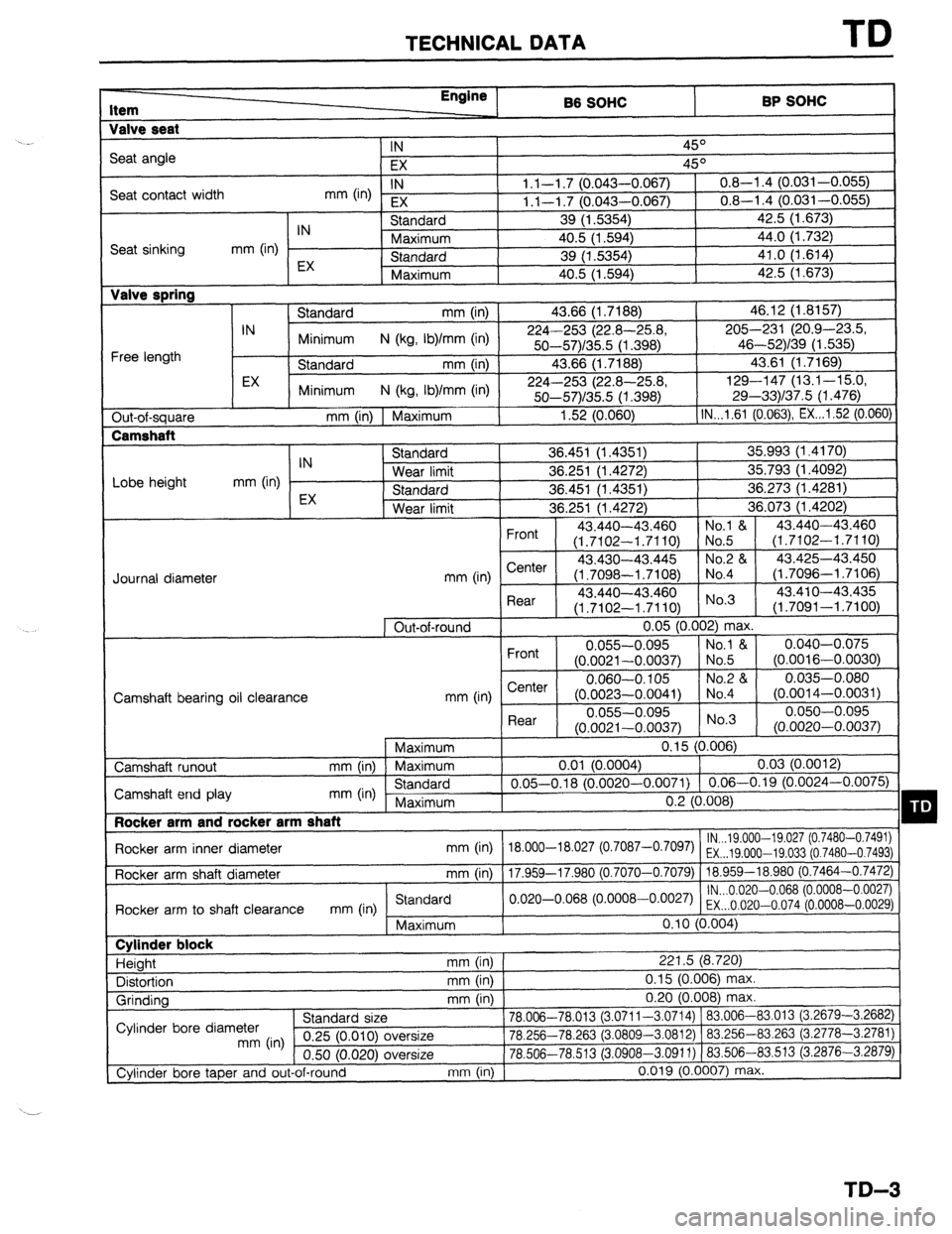
TECHNICAL DATA TD
Item Engine
B6 SOHC BP SOHC
Valve seat
IN
45O
Seat angle
EX 45O
Seat contact width IN
mm 04 EX 1.1-l .7 (0.043-0.067) 0.8-l .4 (0.031-0.055)
1.1-l .7 (0.043-0.067) 0.8-l .4 (0.031-0.055)
IN Standard 39 (1.5354) 42.5 (1.673)
Seat sinking mm (in) Maximum 40.5 (1.594) 44.0 (1.732)
EX Standard 39 (1.5354) 41.0 (1.614)
Maximum 40.5 (1.594) 42.5 (1.673) Valve spring
Standard mm (in) 43.66 (1.7188) 46.12 (1.8157)
IN
Minimum N (kg, Ib)/mm (in) 224-253 (22.8-25.8, 205-231 (20.9-4X3.5,
Free length 50--57)/35.5 (1.398) 46-52)/39 (1.535)
Standard mm (in) 43.66 (1.7188) 43.61 (1.7169)
EX
Minimum N (kg, Ib)/mm (in) 224-253 (22.8-25.8, 129-147 (13.1-15.0,
50-57)/35.5 (1.398) 29-33)/37.5 (1.476)
Out-of-square mm (in) 1 Maximum 1.52 (0.060) IN...l.61 (0.063) EX...1.52 (0.060)
Lobe height mm (in) IN
EX Standard 36.451 (1.4351) 35.993 (1.4170)
Wear limit 36.251 (1.4272) 35.793 (1.4092)
Standard 36.451 (1.4351) 36.273 (1.4281)
Wear limit 36.251 (1.4272) 36.073 (1.4202)
Front 43.440-43 ,460 No.1 & 43.440-43.460
(1.7102-l .7 ‘110) No.5 (1.7102-1.7110)
43.430-43 ,445 No.2 & 43.425-43.450
mm (in) Center
(1.7098-l .7 ‘108) No.4 (1.7096-l .7106)
. , L
Rear 43.440-43.460 No’3 43.41 o-43.435
(1.7102-l .7110) (1.7091-1.7100)
1 Out-of-round 0.05 (0.002) max.
Front 0.055-0.095 No.1 & 0.040-0.075
(0.0021-0.0037) No.5 (0.0016-0.0030)
e--I-.. 0.060-O. 105 No.2 84 0.035-0.080
1041) No.4
“.“-.-..“” (O.OOi 4-0.0031)
Rear 0.055-0.095 0.050-0.095
(0.0021-0.0037) No.3
(0.0020-0.0037)
1 Maximum
0.15 (0.006)
0.01 (0.0004)
0.03 (0.0012)
0.05-0.18 (0.0020-0.0071) 0.06-0.19 (0.0024-0.0075)
n ‘1 m *no Journal diameter
Camshaft hearinn nil cIewanr.F? mm tin I b,er’Ler I (0.0023--0.c
Camshaft runout mm (in) Maximum
Camshaft end play mm (in) Standard
Maximum
I Rocker arm and rocker arm shaft
Rocker arm inner diameter mm (in) 18.000-18.027 (
Rocker arm shaft diameter mm (in)
17 9.59-17 981) I “.L ~“.““O,
lN...19.000--19.027 (0.7480-0.7491)
o.7087-o’70g7) EX...19.000-19.033 (0.7480-0.7493)
I .““” -- -
0 7070-0.7079) 18.959-18.980 (0.7464-0.7472)
lN...0.020-0.068 (0.0008-0.0027)
Rnrkx arm tn shaft clearance
mm (in Standard
I .Y”,.VG 11.,, .” -,,-.. “,“-.“, .I”
““” ,“‘I o.020-o.068 (“~ooo8-o~oo27) EX...O.020-0.074 (0.0008-0.0029)
Maximum 0.10 (0.004) Cylinder block
Height mm (in) 221.5 (8.720)
Distortion mm (in) 0.15 (0.006) max.
Grinding mm (in) 0.20 (0.008) max.
^. , ,
78.006-78.013 (3.0711-3.0714) 183.006-83.013 (3.2679-3.2682)
-.n nr,. -,n fin,% ,n nnnr
” nn’n’ ’ “- T)cc 83.263 (3.2778-3.2781) Cylinder bore diameter stanaara size
mm (in) 0.25 (0.010) oversize IU.L3cl-/U.dDJ (J.uouu-J.uo IL) 1 OJ.LJU--
0.50 (0.020) oversize 78.506-78.513 (3.0908-3.0911) ) 83.506-
Cylinder bore taper and out-of-round mm (in) 0.019 (0.0007) ma: 83.513 i3.2876-3.2879)
I(.
TD-3
Page 1019 of 1164
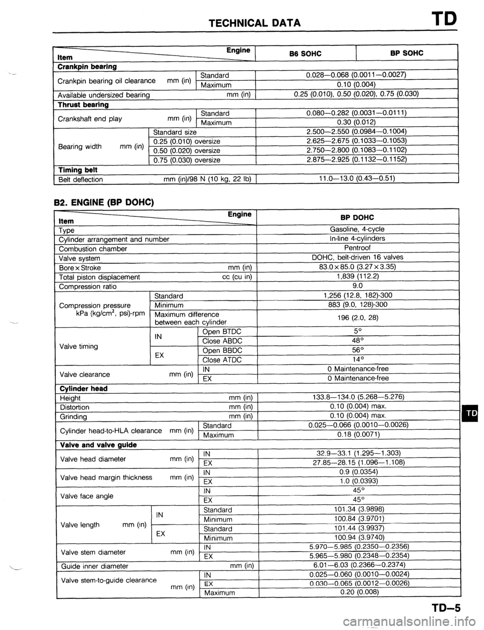
TECHNICAL DATA TD
r-
RP sm.lc: I Item
Crankpin bearing Engine
86 SOHC
I -. VW.._
Crankpin bearing oil clearance mm (in) Standard 0.028-0.068 (0.001 l-0.0027)
Maximum 0.10 (0.004)
Available undersized bearing mm (in)
0.25 (O.OlO), 0.50 (0.020) 0.75 (0.030) Thrust bearing
Crankshaft end play mm (in) Standard 0.080-0.282 (0.0031-0.0111)
Maximum 0.30 (0.012)
Standard size 2.500-2.550 (0.0984-0.1004)
Bearing width mm (in) 0.25 (0.010) oversize 2.625-2.675 (0.1033-0.1053)
0.50 (0.020) oversize 2.750-2.800 (0.1083-0.1102)
0.75 (0.030) oversize 2.875-2.925 (0.1132-0.1152)
1 Timing belt
Belt deflection mm (in)/98 N (10 kg, 22 lb) 1 11 .o-13.0 (0.43-0.51) 82.
ENGINE (BP DOHC) Item
Type
Cylinder arrangement and number BP DOHC
Gasoline, 4-cycle
In-line 4-cylinders
-. I
Combustion chamber
Valve svstem DOHC, belt-d
Bore x Stroke
Total piston displacement ventroot
riven
(3.2:
mm (in) 1 83.0 x 85.0
cc (cu in) ]
7x3.35)1 1,839 (112.2)
I 16 valves I 9.0
-300
mn Compression ratio
Standard 1,256 (12.8, 182)
Compression pressure Minimum 883 (9.0, 128)-Z kPa (kglcm2,
Psi)-rPm
Maximum dif
‘ference
between eat -, h cvlinder 196 (2.0, 28)
IN Open BTDC 5O
Valve timing Close ABDC 48’
EX Open BBDC 56O
Close ATDC .4 In
IY-
IN
mm (in) EX 0 Maintenance-l
Valve clearance
0 Maintenance-i ‘ree
‘me Cylinder head
Height mm (in)
Distortion mm (in)
Grinding mm (in)
Standard
Cylinder head-to-HLA clearance mm (in) Maximum Valve and valve guide 133.8-134.0 (5.268-5.276)
0.10 (0.004) max.
0.10 (0.004) max.
0.025-0.066 (0.0010-0.0026)
0.18 (0.0071)
Valve head diameter IN
mm (in) EX 32.9-33,l (1.295-l ,303)
27.85-28.15 (1.096-1.108)
Valve head margin thickness IN
mm On) Fx 0.9 (0.0354)
1 .o fO.0393)
1 Valve face angle . .
I
FX I I
Valve length IN
Standard 101.34 (3.9898)
mm (in) Minimum 100.84 (3.9701)
Standard 101.44 (3.9937) I -, .
I
Valve stem diameter EX
Minimum loo.94 i3.974oj
IN
mm (in) - EX 5.970-5.985 (0.2350-0.2356)
5.965-5.980 (0.2348-0.2354)
mm (in) I
. , , 6.01-6.03 (0.23 166-0.2374)
1 IN
I 0.025-0.060 (0.0010-0.0024)
3.0012-0.0026)
( Maximum 0.20 (0.008)
I
TD-5
Page 1020 of 1164
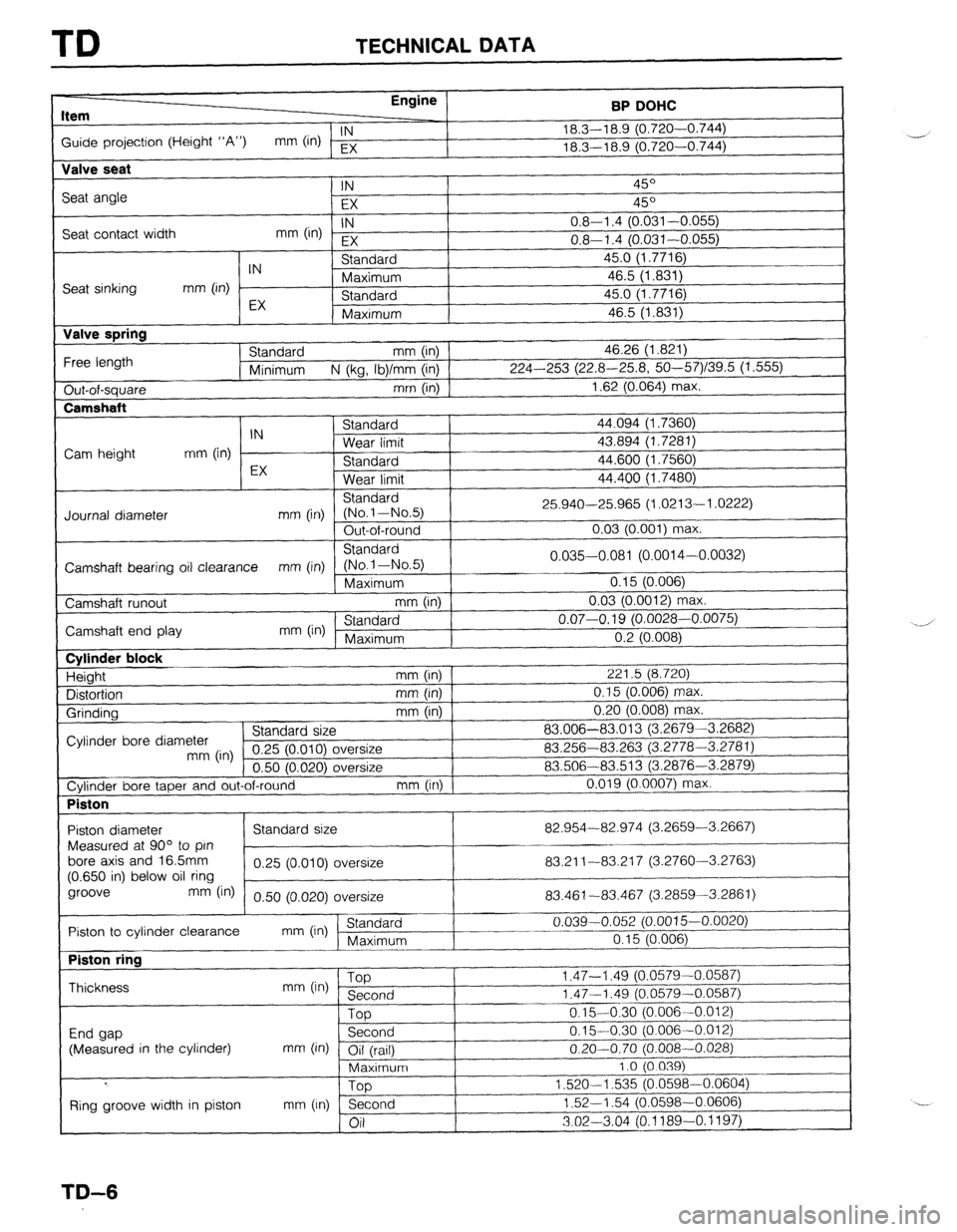
TD TECHNICAL DATA
Item Engine
BP DOHC
Guide projection (Height “A”) IN
mm (in) EX 18.3-l 8.9 (0.720-0.744)
_-j
18.3-l 8.9 (0.720-0.744)
Valve seat
Seat angle
Seat contact width IN 45O
EX 45O
IN
mm (in) EX 0.8-l .4 (0.031-0.055)
0.8-l .4 (0.031-0.055)
Seat sinking
Valve spring
Free length
Out-of-square
Camshaft IN Standard 45.0 (1.7716)
mm (in) Maximum 46.5 (1.831)
EX Standard 45.0 (1.7716)
Maximum 46.5 (1.831)
Standard mm (in) 46.26 (1.821)
Minimum N (kg, Ib)/mm (in) 224-253 (22.8-25.8, 50--57)/39.5 (1.555)
mm (in) 1.62 (0.064) max.
I C+^~rl^.A
44.094 (1.7360)
43.894 (1.7281)
44.600 (1.7560)
44.400 (1.7480) IN 3Ldl l”dl u
Cam height mm (in) Wear limit
EX Standard
Wear limit
Standard
Journal diameter mm (in) (No.l-No.5) 25.940-25.965 (1.0213-l .0222)
Out-of-round 0.03 (0.001) max.
Standard
Camshaft bearing oil clearance mm (in) (No-1-No.5) 0.035-0.081 (0.0014-0.0032)
Maximum 0.15 (0.006)
Camshaft runout mm (in) 0.03 (0.0012) ma
IX.
Camshaft end play mm (in) ’ Standard 0.07-O. 19 (0.0028-0.0075)
Maximum I
I n 9 m mm “.L \“.“““,
Cylinder block
Height
Distortion
Grinding mm (in) 221.5 (8.720)
mm (in) 0.15 (0.006) max.
mm (in) 0.20 (0.008) max.
Cylinder bore diameter Standard size 83.006-83.013 (3.2679-3.2682)
mm (in) 0.25 (0.010) c oversize 83.256-83.263 (3.2778-3.2781)
n.vl IO0701 I -.--
\-----I Jversize 83.506-83.513 (3.2876-3.2879)
Cylinder bore taper and out-of-round mm (in) 0.019 (0.0007) max.
Piston
I
I I
Piston diameter 82.954-82.974 (3.2659-3.2667)
Measured at 90” to pin
bore axis and 16.5mm
83.21 l-83.21 7 (3.2760-3.2763)
(0.650 in) below oil ring
groove
mm fin) 0.50 (0.020) oversize 83.461-83.467 (3.2859-3.2861)
r~ Piston to cylinder clearance
mm On) (Standaid 0.039-0.052 (0.0015-0.0020)
Piston ring
Thickness
End gap
(Measured in the cylinder) mm (in) ‘W
Second
Top
Second
mm (in) Oil (rail)
Maximum
Too I .‘t, - I .ct3 (“.“a, 3-u
1.47-l .49 (0.0579-C
0.1%0:30 (0.006--C
0.15-0.30 (0.006-C
I I.01 2)
0.20-0.70 (0.008-0.028)
1.0 (0.039)
1,520-l
,535 (0.0598-0.0604)
1.52-l .54 (0.0598-0.0606)
3.02-3.04 (0.1189-O. 1197)
I Ring groove width in piston mm (In) n
;_A
TD-6
Page 1025 of 1164
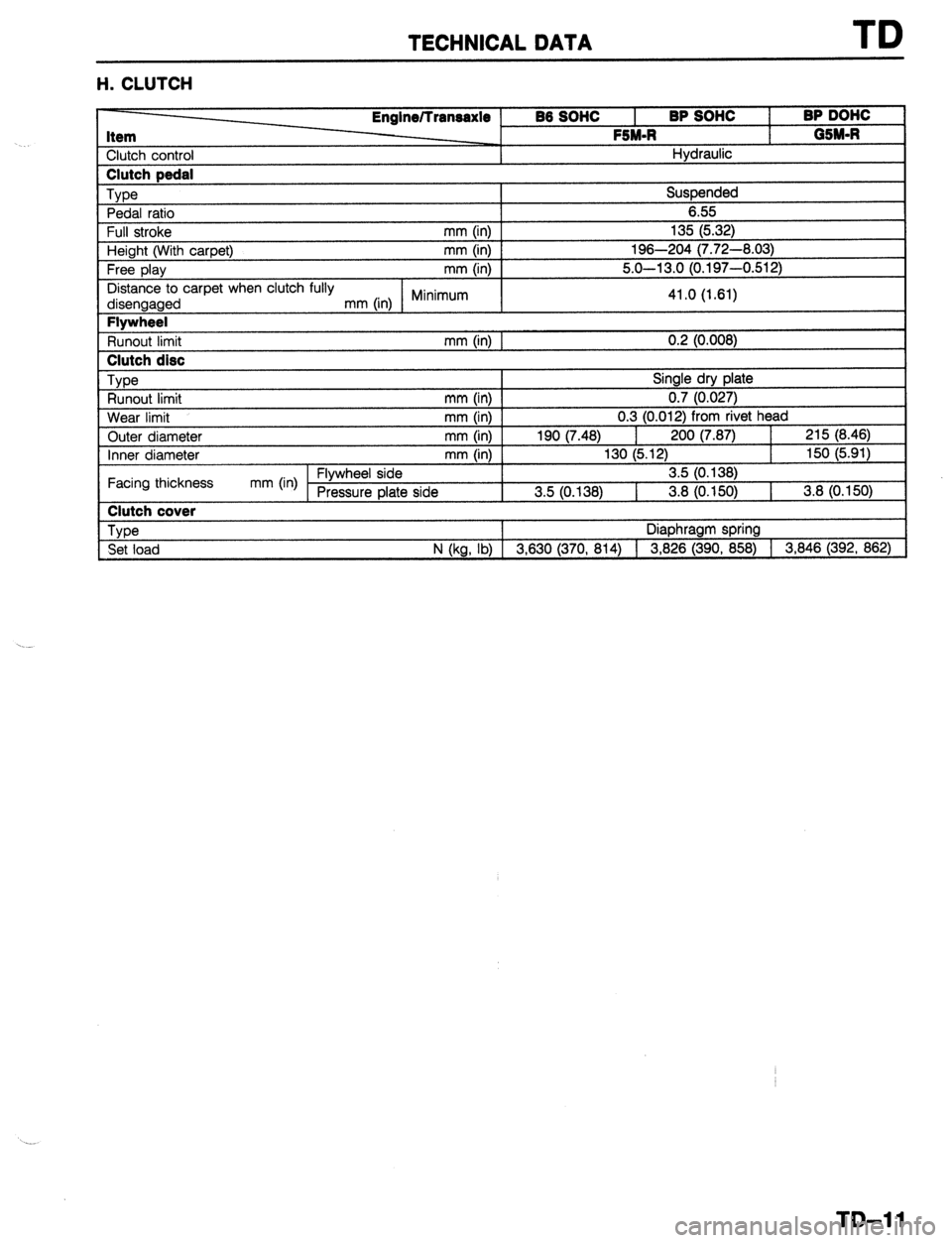
TECHNICAL DATA
H. CLUTCH
1 Full stroke Englne/lransaxle
86 SOW
I BP SOHC
I BP DOW
Item 1 05M-R FSM-R
Clutch control Hydraulic Clutch pedal
Type
Suspended
Pedal ratio 6.55
mm (in) I 135 (5.3 2)
Height (With carpet) mm (in) 1 1E t6-204 (7.72-8.03)
Free olav
L .-- 7 --a mm (in) I
t I , 5.0-l 3.0 (0.197-0.512)
Distance to carpet when clutch fully
disengaged mm (in) Minimum 41.0 (1.61) Flywheel
Runout limit mm (in) I 0.2 (0.008) Clutch disc
, Type
Single dry plate
Runout limit mm (in) 1 LO.027)
Wear limit mm (in) I 0.3 1 (0.012) from rivet head
Outer diameter mm (in)
1s , I )O (7.48) 200 (7.87)
I 215 (8.46)
Inner diameter mm (in) 130 (5 150 (5.91)
-.
Facing thcknes! 3 mm (in) Flywheel side [O. 138)
Pressure elate side 3.5 10.1:
, 38) 3.8 (0.150)
1 3.8 (0.150) Clutch cover
Type
Diaphragm spring
Set load N (kg, lb) [ 3,630 (370, 814) 1 3,826 (390, 858) 1 3,846 (392. 862)
TD-11