Page 1072 of 1164

II-GM6 Troubleshooting
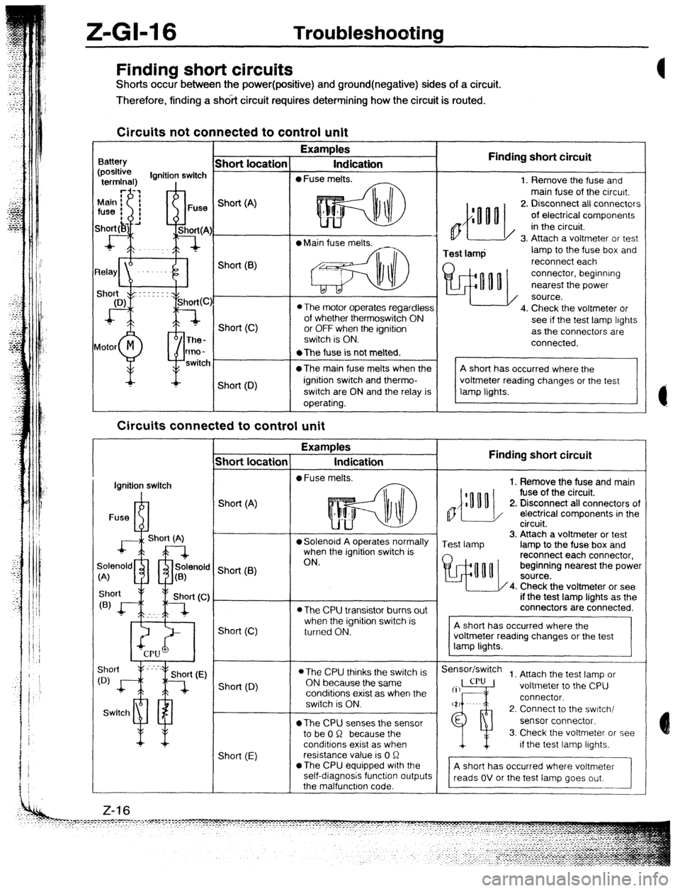
Finding short circuits
Shorts occur between the power(positive) and ground(negative) sides of a circuit.
Therefore, finding a shdit circuit requires determining how the circuit is routed.
Circuits not connected to control unit
Examples
Indication
0 Fuse melts. Finding short circuit
0
Test lamp 1. Remove the fuse and
main fuse of the circurt.
2. Disconnect all connectors
of electrical components
in the circuit.
3. Attach a voltmeter or test
lamp to the fuse box and
reconnect each
connector, beginning
nearest the power
source.
4. Check the voltmeter or
see if the test lamp lights
as the connectors are
connected. Finding short circuit
,,{:““o
1. Remove the fuse and main
fuse of the circuit.
2. Disconnect all connectors of
/ electrical components in the
circuit.
Test lamp 3. Attach a voltmeter or test
lamp to the fuse box and
reconnect each connector,
beginning nearest the power
4. Check the voltmeter or see
if the test lamp lights as the
connectors are connected.
Sensor/switch
1. Attach the test lamp or
voltmeter to the CPU
connector.
2. Connect to the swrtch/
sensor connector.
3. Check the voltmeter or see
if the test lamp lights.
A short has occurred where voltmeter
reads OV or the test lamp goes out,
- Short location
Battery Short (A)
l Main fuse melts.
L* Short(B)
0 The motor operates regardless
of whether thermoswitch ON
or OFF when the ignition
switch is ON. Short (C)
lotor
M
P The-
tmo-
switc *The fuse is not melted.
@The main fuse melts when the
ignition switch and thermo-
switch are ON and the relay is
operating. Short (D)
Circuits connected to control unit
-T Examples
Indication
l Fuse melts.
- Short locatior
I
ignition switch
I
Fuse R-l Short (A)
J+L--l
Short (A) l Solenoid A operates normally
when the ignition switch is
ON.
9enold m rfr solenok
;<
A) u a(B) ’ Short (6)
l The CPU transistor burns out
when the ignition switch is
turned ON. Short (C)
l The CPU thinks the switch is
ON because the same
conditions exist as when the
switch is ON.
*The CPU senses the sensor
to be 0 R because the
conditions exist as when
resistance value is 0 R
*The CPU equipped with the
self-diagnosis function output
the malfunctron code. Short (0)
Swltcl1 ml
Short (E) Z-16
Page 1079 of 1164
HARNESS COLOR : FRUN I - Cm-*m= -
I
FUSE BOX
I
Z-23
STARTER
INTERLOCK
SWITCH
Page 1081 of 1164
HMmESS COLOR : FRONT- ENGINE m WIRING
A-2 !
ALTERNATOR A-04
(GRAY)
ALTERNATOR
FUSE BOX
m MAIN FUSE
Page 1083 of 1164
“.w- MIM . FRONT- ENGINE - REAR - - __._ -._.- -.~ -~ ~.. .-_.--_* . . . . . -...-- --
- WIRING DIAGRAM
IGNITION COIL
IA-VI/ FUSE BOX FUSE BOX
Bl-02
MAIN RELAY
(FUEL INJ)
JOINT BOX
I h
(_an&=y “t Ix-16j
I- 323 HATCHBACH
h-s* A,- (WW
JB-06 DI-U3 . dl, u=nE)
I
IGNITER (GRAY) 4b
s/JB-04 B&M
FUEL TANK “NIT
JOINT
CONNECTOR
A - Bl-01
\W\“ A Bl -03 /
JO& BOX
(F)-o /x-o! (BucI() (F)-(EM) w PROTEGii
Z-27
Page 1099 of 1164
HARNESS COLOR : FRONT m ENGINE m WIRING DIAGRAM z
FUSE BOX
WATER
THERMOSWITCH
F-EM)
,:
z-43
__....._.. _ . . . . .._........ -. .._ _” .._. . . :..--..-.--, .__.
_.__.__.__.-
Page 1101 of 1164
HARNESS COLOR : FRONT- ENGINE m WIRING UlACjl-iAM L
I
B
l-4 -I
FUSE BOX
!it% FAN
RELAY NO.1
FUSE BOX
JOINT BOX
Page 1107 of 1164
HARNESS COLOR : FRONT- ENGINE- WIRING DIAGRAM 2
I
t
l-2J
FUSE BOX
JOINT BOX
JB-Oq
JB-04
JOINT BOX
Page 1109 of 1164
HARNESS COLOR : FRONT m ENGINE- REAR m
I I WIRING DIAGC
JB-03 -
m CRUISE CONTROL) REAR WIPER 8
WASHER SWITCH
D-01
j-zi%y ”
g’b?K, JOINT BOX
CONTROL)
FUSE: BOX
MAIN FUSE
JOINT BOX
REAR WASHER MOTOR
(BLACK)
D-05 REAR WIPER tiOTOR