1992 MAZDA PROTEGE audio
[x] Cancel search: audioPage 955 of 1164

AUDIO T
97UOTX-If
13UOTX-06
/-cl/ /
03UOTX-18:
03UOTX-16 OWOTX-189
6
Inspection
1. Check for resistance with an ohmmeter.
Note
l Set the ohmmeter to xl0 range.
l Redstance: approximately 4h2
2. Confirm that clicking comes from the speaker when touch-
ing the connectors. If not, replace speaker.
REAR SPEAKER
Removal / Installation
(PROTEGe)
1. Remove the fasteners and the rear package trim.
2. Remove the screws and the rear speaker.
(Hatchback)
1. Remove the cover.
2. Remove the screw and the rear speaker.
Inspection
1. Check for resistance with an ohmmeter.
Note
l Set the ohmmeter to xl0 range.
l Resistance: approximately 43
2. Confirm that a clicking comes from the speaker when touch-
ing the connectors. If not, replace the speaker.
ANTENNA FEEDER
Removal
1. Remove the instrument panel. (Refer to Section S.)
2. Remove the front side trim.
T-99
Page 956 of 1164

T AUDIO
OWOTX-167
// 03UOTX-161
OBUOTX-
ANTENNA FEEDER
PLUG
OHMMETER
03UOTX-
3. Remove the antenna feeder from the clip.
4. Remove the screws and antenna assembly.
Installation
1. Extend the antenna.
2. Insert the antenna feeder and the drain pipe in the hole of
the roof.
3. Install in the order shown in the figure.
Inspection
1. Check the antenna with an ohmmeter.
2. If the needle does not indicate infinite, replace the antenna.
T-l 00
Page 1024 of 1164
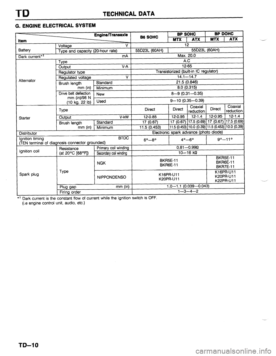
TD TECHNICAL DATA
G. ENGINE ELECTRICAL SYSTEM
3attery Dark
current*’
Alternator 86 SOHC BP SOHC
I BP DOHC
MTX 1 ATX 1 MTX 1 ATX
Voltage V 12
Type and capacity (20-hour rate) 55D23L (60AH) 1 55D23L (60AH)
mA Max. 20.0
Type A.C
output V-A 12-65
Regulator type Transistorized (built-in IC regulator)
Regulated voltage V 14.1-14.7
Brush length Standard 21.5 (0.846)
mm (in) Minimum 8.0 (0.315)
Drive belt deflection
New 8-Q (0.31-0.35)
;riL’F,i Used Q-10 (0.35-0.39)
Coaxial
Type Direct Direct Coaxial
reduction Direct
reductior
Starter output V-kW 12-0.85 12-0.95 12-1.4 12-0.95 12-1.4
Brush length Standard 17 (0.67) 17 (0.67) 17.5 (0.69) 17 (0.67) 17.5 (0.69
mm (in) Minimum 11.5 (0.453) 11.5 (0.453) 10.0 (0.39) 11.5 (0.453) 10.0 (0.39
Distributor Electronic spark advance (photo diode)
Ignition timing BTDC
(TEN terminal of diagnosis connector grounded) 6O-8O 4O-6O 9”-11 O
Ignition coil Resistance Primary coil winding 0.81 -O.QQg
(at 20% [68OF]) Secondary coil winding lo-16 kg
SK&E-1 1 BKR5E-11
NGK
BKRGE-11 BKRGE-11
BKR7E-11
Spark plug Type
NIPPONDENSO KlGPR-Ull
K20PRUll KlGPR-Ull
K20PRUll
K22PRUll *:
. Plug gap
Firing order mm (in) 1.0-l .l (0.039-0.043)
l-3-4-2
---
’ Dark current is the constant flow of current while the ignition switch IS UFF.
(i.e engine control unit, audio, etc.) ..-
._*
T&l 0
Page 1049 of 1164
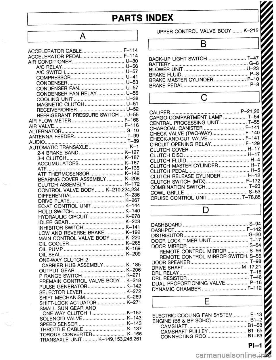
PARTS INDEX
‘I
A
ACCELERATOR CABLE ............................. F-l 14
ACCELERATOR PEDAL ............................. F-l 14
AIR CONDITIONER ...................................... u-30
A/C RELAY.. ........................................... U-56
A/C SWITCH ...........................................
U-57
COMPRESSOR.. ..................................... U-41
CONDENSER.. ....................................... U-53
CONDENSER FAN ................................. u-57
CONDENSER FAN RELAY .................... U-56
COOLING UNIT ..................................... U-38
MAGNETIC CLUTCH ............................. u-51
RECEIVER/DRIER .................................. U-52
REFRIGERANT PRESSURE SWITCH.. .. U-55
AIR FLOW METER ..................................... F-l 68
AIR VALVE.. ................................................ F-l 16
ALTERNATOR .............................................. G-10
ANTENNA FEEDER
AUDIO
....... .......................................................................................... T-i;
AUTOMATIC TRANSAXLE ............................. K-l
2-4 BRAKE BAND ................................ K-l 97
3-4 CLUTCH.. ....................................... K-l 87
ACCUMULATORS ................................ K-l 67
ATF ....................................................... K-135
ATF THERMOSENSOR ........................ K-142
BEARING COVER ASSEMBLY ............ K-208
CLUTCH ASSEMBLY ........................... K-l 72
CONTROL VALVE BODY.. .....
K-21 0,224,234
DIFFERENTIAL ..................................... K-236
DRIVE PLATE.. ..................................... K-267
EC-AT CONTROL UNIT ....................... K-144
HOLD SWITCH ..................................... K-140
HYDRAULIC CIRCUIT .......................... K-278
IDLER GEAR ........................................ K-203
INHIBITOR SWITCH ............................. K-l 41
LOW AND REVERSE BRAKE .............. K-192
MAIN CONTROL VALVE BODY .......... K-220
OIL COOLER.. ...................................... K-265
OIL PUMP ............................................
K-169
OIL SEAL ..............................................
K-209
ONE-WAY CLUTCH 2
CARRIER HUB ASSEMBLY ............... K-185
OUTPUT GEAR .................................... K-206
P RANGE SWITCH.. ............................. K-271
PREMAIN CONTROL VALVE BODY .a. K-218
PULSE GENERATOR ........................... K-142
SELECTOR LEVER ............................... K-272
SHIFT MECHANISM ............................. K-269
SHIFT-LOCK ACTUATOR
..................... K-271
SMALL SUN GEAR AND
ONE-WAY CLUTCH 1 ........................ K-l 82
SOLENOID VALVE.. ............................. K-l 43
SPEEDSENSOR .................................. K-l 43
THROTTLE CABLE .............................. K-l 37
TORQlJE CONVERTER.. ...................... K-l 66
TRANSAXLE UNIT. ......... K-149,153,246,261 UPPER CONTROL VALVE BODY.. ..... K-215
BACK-UP LIGHT SWITCH..
..........................
BATTERY T;4;
- .......................................................
BLOWER UNIT ............................................
U-23
BRAKE FLUID.. .............................................. P-8
BRAKE MASTER CYLINDER. ...................... P-10
BRAKE PEDAL ...............................................
P-8
C
CALIPER .................................................. P-21,26
CARGO COMPARTMENT LAMP ................. T-54
CENTRAL PROCESSING UNIT..
.................. T-55
CHARCOAL CANISTER ............................. F-l 41
CHECK VALVE (TWO-WAY) .......................
CHECK-AND-CUT VALVE - .......................... ;-;b$
CIRCUIT OPENING RELAY.. ...................... F-129
CLUTCH COVER ......................................... H-l 7
CLUTCH DISC ............................................. H-l 7
CLUTCH FLUID ............................................. H-4
CLUTCH MASTER CYLINDER.. .................... H-7
CLUTCH PEDAL ............................................ H-5
CLUTCH RELEASE CYLINDER..
................. H-12
CLUTCH SWITCH (MTX) ............................ F-l 72
COMBINATION SWITCH .............................. T-23
COWL GRILLE ............................................. S-53
CRUISE CONTROL UNIT.. ...................... T-78,85
D
DASHBOARD ............................................... S-94
DASHPOT ................................................... F-l 42
DISTRIBUTOR .............................................. G-20
DOOR LOCK TIMER UNIT ........................... T-17
DOOR MIRROR ............................................ S-54
REMOTE CONTROL MIRROR ............... S-56
REMOTE CONTROL MIRROR SWITCH. S-55
DOOR SPEAKER .......................................... T-98
DRIVE SHAFT.. ....................................... M-l 7,21
DRL RELAY.. ................................................ T-18
DRL RESISTOR ............................................ T-46
DUAL PROPORTIONING VALVE..
............... P-l 6
DYNAMIC CHAMBER ................................ F-l 12
E
ELECTRIC COOLING FAN SYSTEM ........... E-13
ENGINE (B6 & BP SOHC) ........................... Bl-2
CAMSHAFT ..........................................
Bl-58
CAMSHAFT PULLEY ...........................
Bl-65
CONNECTING ROD ............................. 81-63
PI-I
Page 1055 of 1164
Z
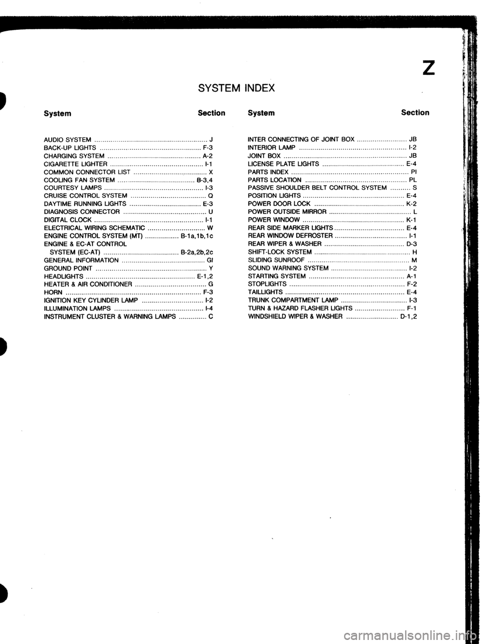
SYSTEM INDEX
System Section System Section
AUDIO SYSTEM ......................................................... J
BACK-UP LIGHTS ...................................................
F-3
CHARGING SYSTEM ............................................... A-2
CIGARETTE LIGHTER ............................................... I-1
COMMON CONNECTOR LIST ..................................... X
COOLING FAN SYSTEM ....................................... B-3.4
COURTESY LAMPS .................................................. l-3
CRUISE CONTROL SYSTEM ...................................... Q
DAYTIME RUNNING UGHTS .................................... E-3
DIAGNOSIS CONNECTOR .......................................... U
DIGITAL CLOCK ....................................................... l-l
ELECTRICAL WIRING SCHEMATIC ............................. W
ENGINE CONTROL SYSTEM (MT) ................. B-l a, 1 b, 1 c
ENGINE 8 EC-AT CONTROL
SYSTEM (EC-AT) ...................................... B-2a,2b,2c
GENERAL INFORMATION .......................................... GI
GROUND POINT ........................................................ Y
HEADLIGHTS ....................................................... E-l ,2
HEATER 8 AIR CONDITIONER .................................... G
HORN .................................................................... F-3
IGNITION KEY CYLINDER LAMP ............................... l-2
ILLUMINATION LAMPS .............................................
l-4
INSTRUMENT CLUSTER . WARNING LAMPS .............. C INTER CONNECTING OF JOINT BOX ......................... JB
INTERIOR LAMP ...................................................... l-2
JOINT BOX .............................................................. JB
LICENSE PLATE UGHTS ......................................... E-4
PARTS INDEX ........................................................... PI
PARTS LOCATION ................................................... PL
PASSIVE SHOULDER BELT CONTROL SYSTEM .......... S
POSITION LIGHTS ................................................... E-4
POWER DOOR LOCK ............................................. K-2
POWER OUTSIDE MIRROR ......................................... L
POWER WINDOW ................................................... K-l
REAR SIDE MARKER LIGHTS.. ................................. E-4
REAR WINDOW DEFROSTER .................................... I-1
REAR WIPER 8 WASHER ........................................ D-3
SHIFT-LOCK SYSTEM ................................................ H
SLIDING SUNROOF ................................................... M
SOUND WARNING SYSTEM ...................................... l-2
STARTING SYSTEM ................................................ A-l
STOPLIGHTS .......................................................... F-2
TAILLIGHTS ............................................................ E-4
TRUNK COMPARTMENT LAMP ................................. l-3
TURN 8 HAZARD FLASHER UGHTS ......................... F-l
WINDSHIELD WIPER 8 WASHER .......................... D-l ,2
Page 1060 of 1164
Z-Gl-4 Reading Wiring Diagrams
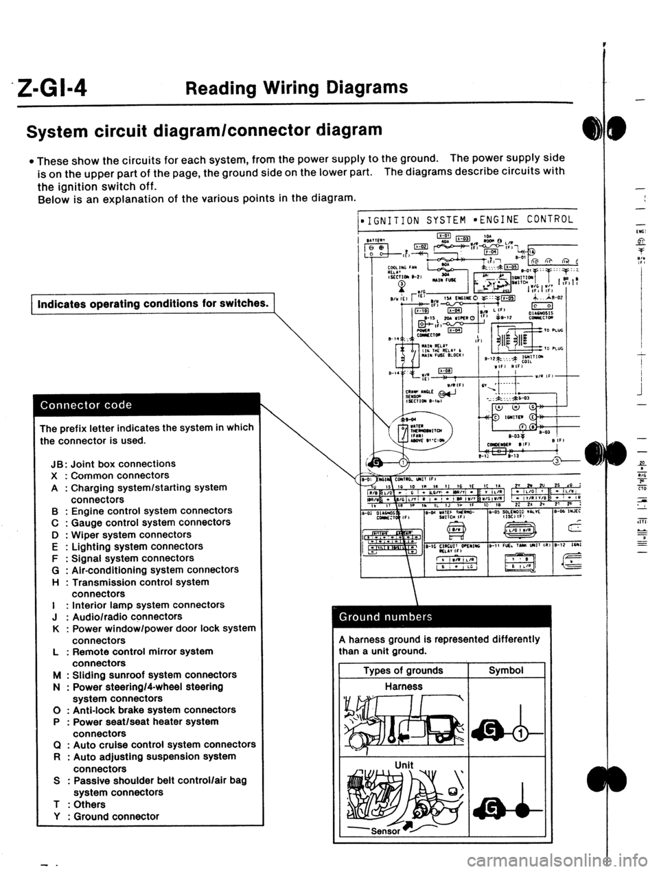
System circuit diagram/connector diagram
l These show the circuits for each system, from the power supply to the ground. The power supply side
is on the upper part of the page, the ground side on the lower part. The diagrams describe circuits with
the ignition switch off.
Below is an explanation of the various points in the diagram.
) Indicates operating conditions for switches.
The prefix letter indicates the system in which
:he connector is used.
JB: Joint box connections
X : Common connectors
A : Charging system/starting system
connectors
B : Engine control system connectors
C : Gauge control system connectors
D : Wiper system connectors
E : Lighting system connectors
F : Signal system connectors
G : Air-conditioning system connectors
H : Transmission control system
connectors
I : Interior lamp system connectors
J : Audio/radio connectors
K : Power window/power door lock system
connectors
L : Remote control mirror system
connectors
M : Sliding sunroof system connectors
N : Power steering/4-wheel steering
system connectors
0 : Anti-lock brake system connectors
P : Power seat/seat heater system
connectors
Cl : Auto cruise control system connectors
R : Auto adjusting suspension system
connectors
S : Passive shoulder belt control/air bag
system connectors
T : Others
Y : Ground connector
- .
1
\\‘
IGNITION SYSTEM l ENGINE CONTROL 9 harness ground is represented differently
:han a unit ground.
Types of grounds Symbol
Harness
I
-
-
-
-
‘“G:
si-
P
7:’
.I
I
I
.i
-
-
-
f
9
Tiii
zs
LL
a
EE
-
Page 1136 of 1164

: WIRINQ DIAQRAM
m AUDIO SYSTEM
O...WITH POWER WINDOW
1 J
B (F)
RADIO
15A
,I
\ I
JB-02
AUDIO ILLUMINATION LAMP:
REFER TO SECTION I-4
:J-01
AUDIO SYSTEM
J-01 AUDIO SYSTEM (I)
0 v R/B L/R L/B
w L/O * * ++ * *
J-03 DOOR SPEAK:$$ J-04 DOOR SPEAKER RH
< J-02 AUDIO SYSTEM (I)
* * W/L
x.
L L/W
* B/L
J-05 REAR;SPEAKER(k; J-06 REAR SPEAKER I+
(R)
Z-80
Page 1137 of 1164
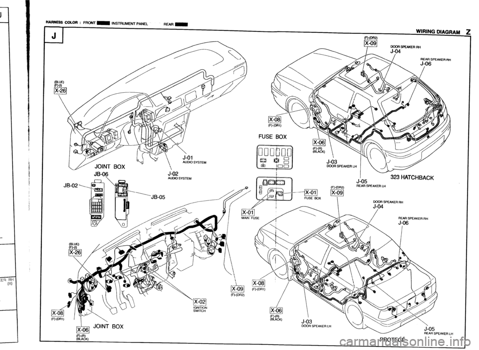
-
-
iU&i SYSTEM
JB-06
JB-02 >q J-02 AUDIO SYSTEM HARllESS COLOR : FRONT m INSTRUMENT PANEL
RMmm
J 1 WIRING DIAGRAM FbmFw~
J-US
,!=U~c1B REAR SPEAKER LH
.--kKA / REAR SPEAKER RH OOOR SPEAKER RH
ww
(-CK) PROTEGC
ARSPEAKERLH