1992 MAZDA PROTEGE alternator belt
[x] Cancel search: alternator beltPage 450 of 1164

G
ALTERNATOR
Removal / Installation
CHARGING SYSTEM
Caution
l Be sure the battery connections are not reversed, because this will damage the rectifier.
l Do not use high-voltage testers such as a megger, because they will damage the rectifier.
l Remember that battery voltage is always applied to the alternator B terminal.
l Do not ground the L terminal while the engine is running.
l Do not start the engine while the connector is disconnected from the L and S terminals.
1. Remove in the order shown in the figure.
2. Inspect all parts and repair or replace as necessary
3. Install in the reverse order of removal.
N.m (m-kg, R-lb)
OSlJOGX b20
1. Negative battery cable
2. Vacuum hose
3. Solenoid bracket (If equipped)
4. Connector
5. B terminal wire
Inspect for damage and corroston 6. Drive belt
Inspection. . . . ., ~.. ,. ,.... . , page G-l 4
Adjustment ,~, ,.,., ,. ,. ,, ,.. page G-l 4
Replacement . . . . . . . . page
G-l 4
7. Alternator
Disassembly / Assembly ,........,... page G-l 1
Inspection... ,, . . . . . . . . . . . . . . . . . . . . . . . . . . . page G-l 2
G-10
Page 454 of 1164

G CHARGING SYSTEM
WATER PUMP 13UOGX-00,
03UOGX-03:
I /I I III
I f 03UOGX-03:
03UOGX-034
DRIVE BELT
Inspection
1. Check the drive belt and pulley for wear, cracks, and fray-
ing. Replace if necessary.
2. Measure the drive belt tension with a tension gauge. .-A
Tension N (kg, lb)
Drive belt
Alternator
A/C and P/S New Used
383-461
304-303
(39-47, 85.8-103.4) (31-39, 68.2-85.8)
491-589 422-491
(50-60, 11 O-l 32) (43-50, 95-110)
3. Measure the deflection by applying moderate pressure (98
N, 10
kg, 22 lb) midway between the pulleys. Adjust if
necessary.
Deflection mm (in)
Drive belt
Alternator
AIC and P/S New Used
8-9 9-10
(0.31-0.35) (0.35-0.39)
8-9 9-10
(0.31-0.35) (0.35-0.39)
Adjustment
1. Loosen the alternator mounting bolt and adjusting bolt.
2. Move the alternator to set the specified deflection.
3. Tighten all bolts and recheck the tension.
Replacement
1. Remove the A/C and P/S drive belt, if equipped.
Note
l Refer to pages 61-5 and 82-5.
2. Loosen the alternator mounting bolt and adjusting bolt.
3. Remove the alternator belt.
4. Install the new alternator belt and adjust it to specification.
5. Tighten all bolts to the specified torque.
Tightening torque
Alternator bolt:
37-52 N#rn (3.8-5.3 m-kg, 27-38 ft-lb)
Adjusting bolt:
19-25 N-m (1.9-2.6 m-kg, 14-19 ft-lb)
6. Install the A/C and P/S drive belt if equipped, and adjust
to specification.
Note
l Refer to pages 61-5 and 82-5.
G-14
Page 869 of 1164

FUSE AND JOINT BOX
FUSES
Specifications
Main fuse block
Fuse Color
FUEL INJ 30A Pink
HEAD 30A Pink
MAIN 80A Black
BTN 60A Green
AD FAN 30A Pink
ST SIG 10A Red
ELEC FAN 30A Pink Protected circuit
EGI system
Headlight
Cooling fan, Power window, Sunroof, Wiper and washer, Air conditioner
Door lock, Charging system
Additional cooling fan
Fuel pump
Cooling fan
Fuse box
23UOTX-001
Specifications
Fuse
REAR WIPER 10A
HAZARD 15A
ROOM IOA
ENGINE 15A
RADIO 15A
DOOR LOCK 30A
BELT 30A
POWER WINDOW 30A Color
Red
Blue
Red
Blue
Blue
Green
Green
Green Protected circuit
Rear wiper and washer
Hazard warning
Clock, interior lamp, Cargo compartment lamp, Trunk compartment lamp
Alternator
Audio
Power door lock
Passive shoulder belt
Power window
1
T-13
Page 920 of 1164

2L BUZZER 2A 28 2C 2D 1A 3K l--r nnmn
I I‘ I
1C 3L 2E 2G IL iG 1F 1D tB
3F 38 3G 1E 3D
l-l rt
II l-l
l-l It II l-l 1J 11 1H
1G IF 1E 1D 1C 1B 1A 2L 2K 2J 21 2H 2G 2F 2E 2D 2C 28 2A
r-l It ,I 3L 3K 3J 31 3H 3G 3F 3E 3D 3C 3B 3A
Ter- I I minal Connected to 1 1A Combination switch
1B Ground
IC Fuel tank unit
1 ID 1 EGI control unit
I
II L 1J 1
L Ter-
minal Connected to
2A Speed sensor output
28 Light switch (high beam)
2C Turn switch (L)
20 Turn switch (R)
2E Ground
2F Ground
2L 1 IGI battery Ter-
minal Connected to
3A
38 Alternator
3c
30 Oil pressure switch
3E
3F Parking brake switch, Brake fluid switch
3G Passive shoulder belt control unit
3H h
I 31
3J
3K
IG2 battery
3L Water temperature gauge unit
Page 1024 of 1164

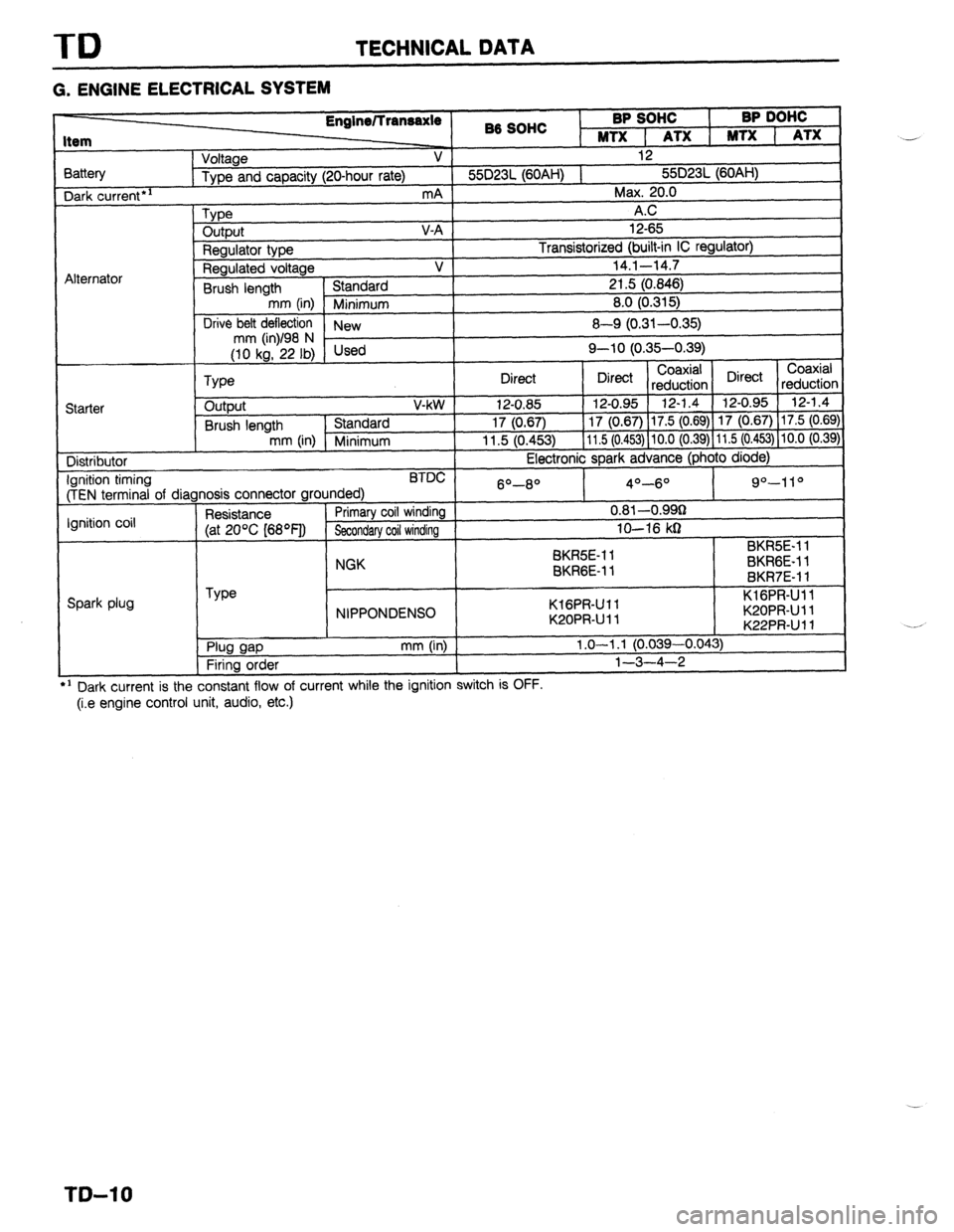
TD TECHNICAL DATA
G. ENGINE ELECTRICAL SYSTEM
3attery Dark
current*’
Alternator 86 SOHC BP SOHC
I BP DOHC
MTX 1 ATX 1 MTX 1 ATX
Voltage V 12
Type and capacity (20-hour rate) 55D23L (60AH) 1 55D23L (60AH)
mA Max. 20.0
Type A.C
output V-A 12-65
Regulator type Transistorized (built-in IC regulator)
Regulated voltage V 14.1-14.7
Brush length Standard 21.5 (0.846)
mm (in) Minimum 8.0 (0.315)
Drive belt deflection
New 8-Q (0.31-0.35)
;riL’F,i Used Q-10 (0.35-0.39)
Coaxial
Type Direct Direct Coaxial
reduction Direct
reductior
Starter output V-kW 12-0.85 12-0.95 12-1.4 12-0.95 12-1.4
Brush length Standard 17 (0.67) 17 (0.67) 17.5 (0.69) 17 (0.67) 17.5 (0.69
mm (in) Minimum 11.5 (0.453) 11.5 (0.453) 10.0 (0.39) 11.5 (0.453) 10.0 (0.39
Distributor Electronic spark advance (photo diode)
Ignition timing BTDC
(TEN terminal of diagnosis connector grounded) 6O-8O 4O-6O 9”-11 O
Ignition coil Resistance Primary coil winding 0.81 -O.QQg
(at 20% [68OF]) Secondary coil winding lo-16 kg
SK&E-1 1 BKR5E-11
NGK
BKRGE-11 BKRGE-11
BKR7E-11
Spark plug Type
NIPPONDENSO KlGPR-Ull
K20PRUll KlGPR-Ull
K20PRUll
K22PRUll *:
. Plug gap
Firing order mm (in) 1.0-l .l (0.039-0.043)
l-3-4-2
---
’ Dark current is the constant flow of current while the ignition switch IS UFF.
(i.e engine control unit, audio, etc.) ..-
._*
T&l 0
Page 1162 of 1164

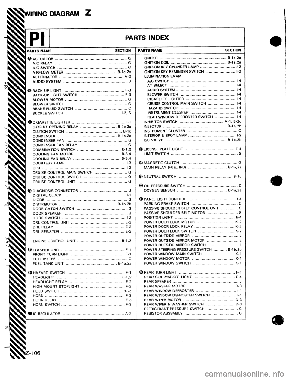
DIAGRAM Z
rl PARTS NAME
-
PA ,K
SECTION T
CIGARETTE LIGHTER ............................................
I-1
CIRCUIT OPENING RELAY ..............................
B-l&Pa
I CLUTCH
SWITCH .............................................. B-lc
CONDENSER ................................................. B-la.2a
CONDENSER FAN ..................................................
G
CONDENSER
FAN RELAY ....................................... G
COMBINATION
SWITCH .................................... E-l.2
COOLING FAN MOTOR .....................................
B-3,4
COOLING
FAN RELAY ........................................ B-3,4
COURTESY LAMP ................................................
l-3
CPU .................................................................... l-2
CRUISE CONTROL
MAIN SWITCH ........................... Q
CRUISE
CONTROL SWITCH .................................... Q
CRUISE CONTROL UNIT ......................................... Q 0 ACTUATOR ........................................................... Q
A/C RELAY ........................................................... G
t A/C SWITCH .........................................................
G
t AIRFLOW METER .......................................... B-lc,Pc
t ALTERNATOR .....................................................
A-2
I AUDIO SYSTEM .....................................................
J
@BACK-UP LIGHT .................................................. F-3
BACK-UP LIGHT SWITCH
..................................... F-3
I
BLOWER MOTOR ...................................................
G
h BLOWER SWITCH ..................................................
G
I BRAKE FLUID SWITCH ...........................................
C
BUCKLE SWITCH .............................................
l-2, S
@I DIAGNOSIS CONNECTOR .......................................
U
DIGITAL CLOCK
................................................... l-l
DIODE ..................................................................
G
DISTRIBUTOR ...............................................
B-l b,2b
DOOR CATCH SWITCH .......................................... S
DOOR
SPEAKER ..................................................... J
DOOR SWITCH ....................................................
l-2
DRL CONTROL UNIT ............................................
E-3
DRL RELAY .........................................................
E-3
ORL RESISTOR ....................................................
E-3
ENGINE CONTROL UNIT
.................................... B-1.2
ii@ FLASHER UNIT ....................................................
F-l
FRONT TURN LIGHT ............................................
F-l
FUEL METER
......................................................... C
FUEL
TANK UNIT .......................................... B-la,2a
HAZARD SWITCH ...............................................
F-l _
HEADLIGHT .....................................................
E-l.2
HEADLIGHT RELAY .............................................
E-2
h HIGH
MOUNT STOPLIGHT ....................................
F-2
h HOLD SWITCH .................................................. B-2c
4 HORN .................................................................
F-3
! HORN RELAY
...................................................... F-3
HORN SWITCH ....................................................
F-3
0 IC REGULATOR ..................................................
A-2
-L
T-S INDEX
PARTS NAME SECTION
IGNITER ........................................................ B-la,2a
IGNITION COIL ..............................................
B-la.2a
IGNITION KEY CYLINDER LAMP .............................
l-2
IGNITION KEY REMINDER SWITCH ........................ l-2
ILLUMINATION LAMP
A/C SWITCH ..................................................... l-4
AT SELECT
....................................................... l-4
AUDIO SYSTEM
................................................. l-4
BLOWER SWITCH .............................................
l-4
CIGARETTE LIGHTER
......................................... l-4
CRUISE CONTROL
MAIN SWITCH ....................... l-4
HAZARD SWITCH .............................................
l-4
INSTRUMENT CLUSTER
..................................... l-4
REAR WINDOW DEFROSTER SWITCH
................. l-4
INHIBITOR SWITCH .................................... A-l, B-2c
INJECTOR ....................................................
B-1 b,2b
INSTRUMENT CLUSTER ..........................................
C
INTERIOR & SPOT LAMP .......................................
l-2
ISC VALVE ...................................................
B-1 b,26
@ LICENSE PLATE LIGHT .........................................
E-4
LIMIT SWITCH .......................................................
S
481 MAGNETIC
CLUTCH .............................................. G
MAIN RELAY (FUEL INJ) ................................
B-la,Pa
@ NEUTRAL SWITCH ............................................
B-lc
@ OIL PRESSURE SWITCH ..........................................
C
OXYGEN SENSOR ......................................... B-la.2a
@ PANEL LIGHT CONTROL .......................................
l-4
PARKING BRAKE SWITCH ......................................
C
PASSIVE SHOULDER BELT CONTROL UNIT
.............. S
PASSIVE SHOULDER BELT
MOTOR .......................... S
POSITION LIGHT .................................................
E-4
POWER DOOR LOCK MOTOR
............................... K-2
POWER DOOR LOCK RELAY
................................. K-2
POWER DOOR LOCK SWITCH
.............................. K-2
POWER
OUTSIDE MIRROR ...................................... L
POWER OUTSIDE MIRROR MOTOR
.......................... L
POWER OUTSIDE MIRROR SWITCH .........................
L
POWER STEERING PRESSURE SWITCH ........... B-l b.2b
POWER WINDOW MAIN SWITCH .........................
K-l
POWER WINDOW MOTOR ...................................
K-l
POWER WINDOW SWITCH
.................................. K-l
@ REAR TURN LIGHT ..............................................
F-l
REAR SiDE MARKER LIGHT ..................................
E-4
REAR
SPEAKER ......................................................
J
REAR WASHER MOTOR ......................................
D-3
REAR WINDOW DEFROSTER
................................. I-1
REAR WINDOW DEFROSTER SWITCH ....................
I-1
REAR WIPER MOTOR
.......................................... D-3
REAR WIPER & WASHER SWITCH
........................ D-3
REFRIGERANT PRESSURE SWITCH
.......................... G
RESISTOR ASSEMBLY ............................................
G