1992 MAZDA PROTEGE width
[x] Cancel search: widthPage 927 of 1164

INSTRUMENT CLUSTER T
(For Canada)
(For USA)
11
OSUOTX-114
Standard Indication
(rpm)
1,000
2,000
3,000
4,000
5,000
6,000
7,000
8,000 Allowable range
@pm)
880-l ,060
1,970-2,150
3,000-3,180
4,000-4,240
5,000-5,300
6,000-6,360
7.000-7.420
8:600-8:480
03UOTX-11 5
I 23UOTX-044 WI TACHO WIO MACHO
32.50
ssn
9MUOTX-087
Inspection
Speedometer
1. Using a speedometer tester, check the speedometer for ai-
lowable indication error, and check the operation of the
odometer. Replace if necessary.
2. Check the speedometer for fluctuation and/or abnormal
noise.
Caution
l If significant fluctuation occurs or the speedome-
ter does not move at all, remove the speedometer
cable. If it is normal, replace the speedometer as-
sembly.
l Tire wear and improper inflation will Increase
speedometer error.
Tachometer
1. Connect a test tachometer to the engine, and start the
engine.
2. Check the tachometer for allowable indication error. Replace
if necessary.
Caution
l When removing or installing the tachometer, do not
drop it or subject it to sharp shocks.
Fuel gauge
1. Remove the instrument cluster. (Refer to page T-69.)
2. Apply battery voltage to terminal 2L and ground terminal 2E.
3. Connect the red lead of the
SST to terminal 1C and the
black lead to a negative battery terminal.
4. Set the
SST to the resistance values shown in the figure.
5. Verify that the needle indicates the correct values.
Caution
l Continue the above checks for at least two minutes
each to correctly judge the condition.
l The allowable indication error is twice the width of
the needle.
T-71
Page 928 of 1164

T INSTRUMENT CLUSTER
I
23UOTX-045
W/ TACHO WI0 TACHO
QMUOTX-08!
03UOTX- 11,
03UOTX.11
OBUOTX-
T-72
Water temperature gauge
1. Remove the instrument cluster. (Refer to page T-69.)
2. Apply battery voltage to terminal 2L and ground terminal 2E.
3. Connect the red lead of the SST to terminal 3L and the black
lead to a negative battery terminal.
____,
4. Set the SST to the resistance values shown in the figure.
5. Turn the ignition switch ON, and verify that the needle indi-
cates the correct values.
Cautlon
l Continue the above checks for at least two minutes
each to correctly judge the condition.
l The allowable indication error is twice the width of
the needle.
Speed sensor
1. Remove the instrument cluster.
2. Check continuity between terminals 2A and 2F while rotat-
ing the speedometer cable shaft.
3. If there are not four pulses per shaft rotation, replace the
speed sensor.
WATER THERMOSENSOR
Removal / Installation
1. Remove the connector.
2. Remove the thermosensor.
3. Install in the reverse order of removal.
Inspection 1.
Remove the sensor.
2. Place the sensor in water.
3. Heat the water gradually, and check the resistance of the
sensor with an ohmmeter. 4.
If the resistance is not as specified, replace the sensor.
Resistance: 190-2603 at 5O*C (122OF)
Page 1016 of 1164
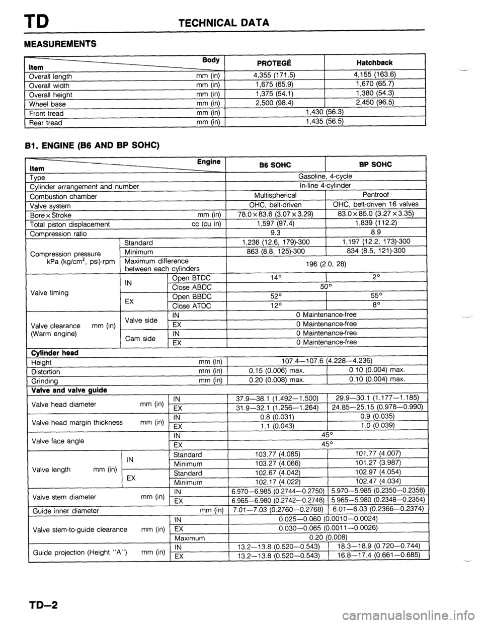
TD TECHNICAL DATA
MEASUREMENTS
I ._.____2_ nem
Overall length
Overall width
Overall height
Wheel base
Front tread
Rear tread Body ) mm (in)
mm (in)
mm (in)
mm (in)
mm (in)
mm (in) PRfWFr.f! . . ..s .-VW Hatchback 4,355 (171.5) 4,155 (163.6)
1,675 (65.9) 1,670 (65.7)
1,375 (54.1) 1,380 (54.3)
2,500 (98.4) 2,450 (96.5)
1,430 (56.3)
1,435 (56.5)
Bl. ENGINE (B6 AND BP SOHC)
1 Type
1 Cylinder arrangement and number Engine
86 SOHC BP SOHC
^ . . _
,?
I
uasollne, 4-cyw
. . *. 4
in-line 4-cyrinaer
Pentroof
1
I Combustion chamber I Multispherical
J Valve system OHC, belt-driven OHC, belt-driven 16 valves
. , I (3.07 x 3.29) 83.0 x 85.0 (3.27 x 3.35)
Total piston displacement cc (cu in) 1,597 (97.4) 1,839 (112.2)
Compression ratio 9.3 8.9
) Standard 1,236 (12.6, 179)-300 1,197 (12.2, 173)300
I
863 (8.8, 125)-300 834 (8.5, 121)300 1 Bore x Stroke
mm (in) I 78.0 x 83.6
Compression pressure
kPa (kg/cm’, psi)-rpm
E cvlinders 1 Maximum difference
196 (2.0, 28)
I
, ------- ---- -J - IN Open BTDC 14O 2O
Close ABDC 50°
Valve timing
Open BBDC 52O 55O
EX
Close ATDC 12O 8O
IN 0 Maintenance-free I \/AIo &-in --
Valve clearance EX 0 Maintenance-free
(Warm engine) mm (in) / ,,syi: 1
IN 0 Maintenance-free
I , EX 0 Maintenance-free
I Cylinder head
Height
Distortion
Grinding Valve and T _
Valve head diameter
Valve head margin thickness
Valve face angle IN mm (in) EX
IN
mm b-4 Fx mm (in) 107.4-107.6 (4.228-4.236)
mm (in) 0.15 (0.006) max. 0.10 (0.004) max.
mm (in) 0.20 (0.008) max. 0.10 (0.004) max.
37.9-38.1 (1.492-l ,500) 29.9-30.1 (1.177-1.185)
31 .Q-32.1 (1.256-l ,264) 24.85-25.15 (0.978-0.990)
0.8 (0.031) 0.9 (0.035)
1.1 10.043) 1 .o (0.039)
-, ,
\- I
IN 45O
EX 45O
I I Standard
IN
Minimum
Valve length mm (in)
EX Standard
Minimum I”L. I, \*.“cL
Valve stem diameter IN
mm On) EX 6.970-6.985 (0.2744-
6.965-6.980 (0.2742-
Guide inner diameter
I Valve stem-to-guide clearance mm (in) lTj7---- ,
Maximum 103.77 (4,085) 101.77 (4.007)
103.27 (4.066) 101.27 (3.987)
102.67 (4.042) 102.97 (4.054)
,n+ 47 IA noo
1 102.47 (4.034)
-0.2750) 5.970-5.985 (0.2350-0.2356)
-0.2748) 5.965-5.980 (0.2348-0.2354)
3.2760-0.2768) 6.01-6.03 (0.2366-0.2374)
0.025-0.060 (0.001 O-0.0024)
0.030-0.065 (0.001 l-0.0026)
-.
I
mm (in) 1 7.01-7.03 (r ‘
1 IN
Guide projection (Height “A”) IN
mm (in) Ex 13.2-l 3.8 (0.520-
13.2-13.8 (0.520-
TD-2
Page 1017 of 1164
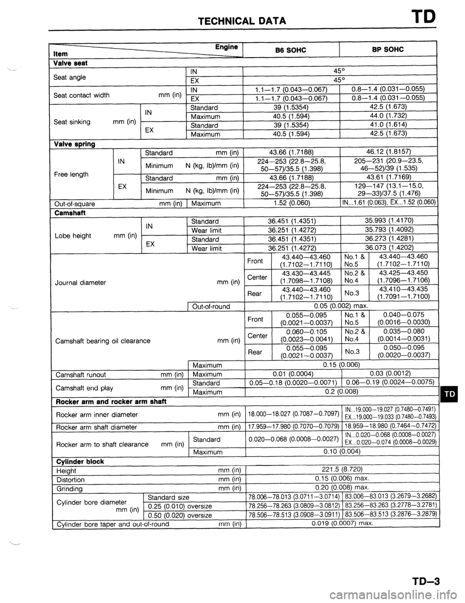
TECHNICAL DATA TD
Item Engine
B6 SOHC BP SOHC
Valve seat
IN
45O
Seat angle
EX 45O
Seat contact width IN
mm 04 EX 1.1-l .7 (0.043-0.067) 0.8-l .4 (0.031-0.055)
1.1-l .7 (0.043-0.067) 0.8-l .4 (0.031-0.055)
IN Standard 39 (1.5354) 42.5 (1.673)
Seat sinking mm (in) Maximum 40.5 (1.594) 44.0 (1.732)
EX Standard 39 (1.5354) 41.0 (1.614)
Maximum 40.5 (1.594) 42.5 (1.673) Valve spring
Standard mm (in) 43.66 (1.7188) 46.12 (1.8157)
IN
Minimum N (kg, Ib)/mm (in) 224-253 (22.8-25.8, 205-231 (20.9-4X3.5,
Free length 50--57)/35.5 (1.398) 46-52)/39 (1.535)
Standard mm (in) 43.66 (1.7188) 43.61 (1.7169)
EX
Minimum N (kg, Ib)/mm (in) 224-253 (22.8-25.8, 129-147 (13.1-15.0,
50-57)/35.5 (1.398) 29-33)/37.5 (1.476)
Out-of-square mm (in) 1 Maximum 1.52 (0.060) IN...l.61 (0.063) EX...1.52 (0.060)
Lobe height mm (in) IN
EX Standard 36.451 (1.4351) 35.993 (1.4170)
Wear limit 36.251 (1.4272) 35.793 (1.4092)
Standard 36.451 (1.4351) 36.273 (1.4281)
Wear limit 36.251 (1.4272) 36.073 (1.4202)
Front 43.440-43 ,460 No.1 & 43.440-43.460
(1.7102-l .7 ‘110) No.5 (1.7102-1.7110)
43.430-43 ,445 No.2 & 43.425-43.450
mm (in) Center
(1.7098-l .7 ‘108) No.4 (1.7096-l .7106)
. , L
Rear 43.440-43.460 No’3 43.41 o-43.435
(1.7102-l .7110) (1.7091-1.7100)
1 Out-of-round 0.05 (0.002) max.
Front 0.055-0.095 No.1 & 0.040-0.075
(0.0021-0.0037) No.5 (0.0016-0.0030)
e--I-.. 0.060-O. 105 No.2 84 0.035-0.080
1041) No.4
“.“-.-..“” (O.OOi 4-0.0031)
Rear 0.055-0.095 0.050-0.095
(0.0021-0.0037) No.3
(0.0020-0.0037)
1 Maximum
0.15 (0.006)
0.01 (0.0004)
0.03 (0.0012)
0.05-0.18 (0.0020-0.0071) 0.06-0.19 (0.0024-0.0075)
n ‘1 m *no Journal diameter
Camshaft hearinn nil cIewanr.F? mm tin I b,er’Ler I (0.0023--0.c
Camshaft runout mm (in) Maximum
Camshaft end play mm (in) Standard
Maximum
I Rocker arm and rocker arm shaft
Rocker arm inner diameter mm (in) 18.000-18.027 (
Rocker arm shaft diameter mm (in)
17 9.59-17 981) I “.L ~“.““O,
lN...19.000--19.027 (0.7480-0.7491)
o.7087-o’70g7) EX...19.000-19.033 (0.7480-0.7493)
I .““” -- -
0 7070-0.7079) 18.959-18.980 (0.7464-0.7472)
lN...0.020-0.068 (0.0008-0.0027)
Rnrkx arm tn shaft clearance
mm (in Standard
I .Y”,.VG 11.,, .” -,,-.. “,“-.“, .I”
““” ,“‘I o.020-o.068 (“~ooo8-o~oo27) EX...O.020-0.074 (0.0008-0.0029)
Maximum 0.10 (0.004) Cylinder block
Height mm (in) 221.5 (8.720)
Distortion mm (in) 0.15 (0.006) max.
Grinding mm (in) 0.20 (0.008) max.
^. , ,
78.006-78.013 (3.0711-3.0714) 183.006-83.013 (3.2679-3.2682)
-.n nr,. -,n fin,% ,n nnnr
” nn’n’ ’ “- T)cc 83.263 (3.2778-3.2781) Cylinder bore diameter stanaara size
mm (in) 0.25 (0.010) oversize IU.L3cl-/U.dDJ (J.uouu-J.uo IL) 1 OJ.LJU--
0.50 (0.020) oversize 78.506-78.513 (3.0908-3.0911) ) 83.506-
Cylinder bore taper and out-of-round mm (in) 0.019 (0.0007) ma: 83.513 i3.2876-3.2879)
I(.
TD-3
Page 1018 of 1164
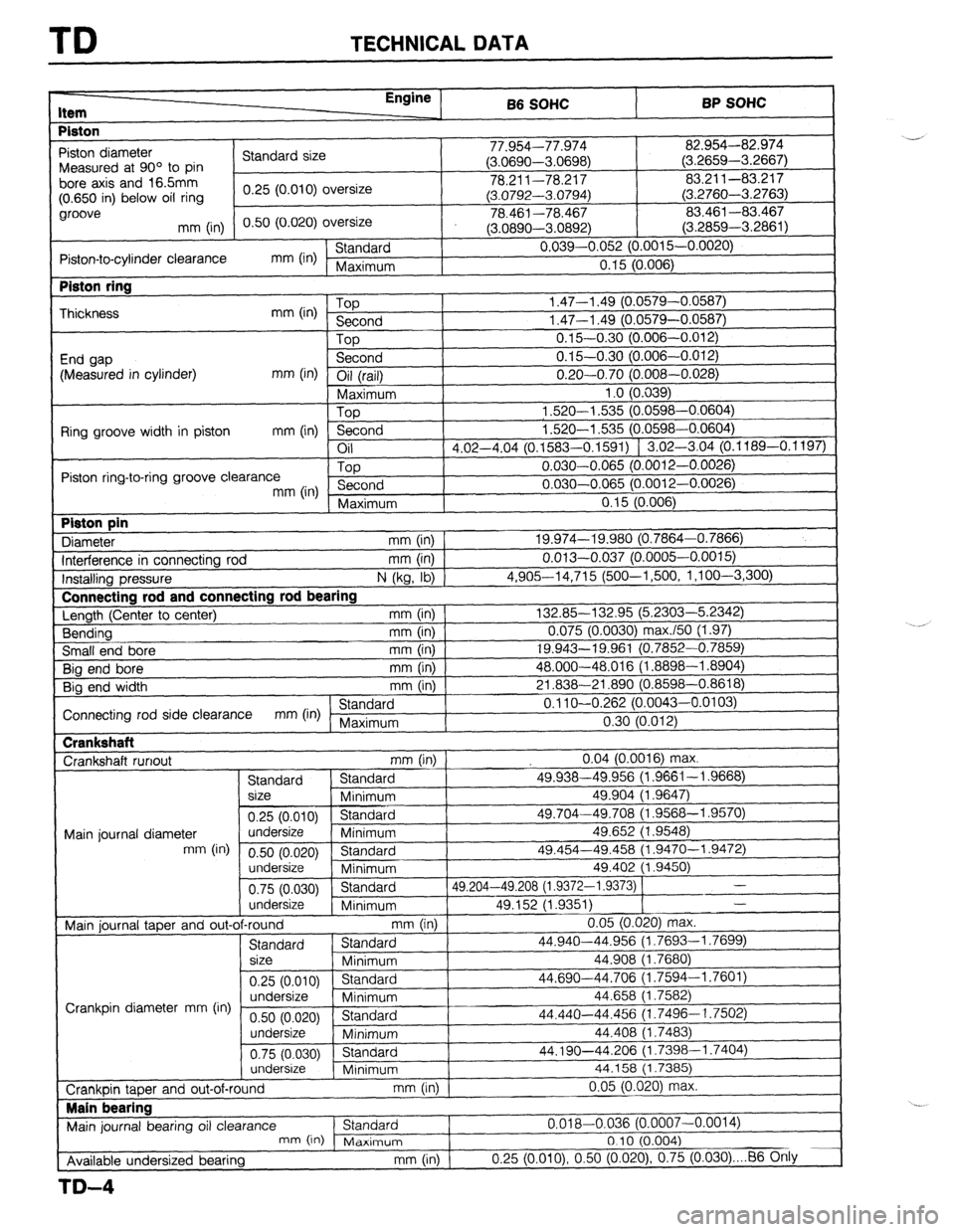
TD TECHNICAL DATA
I-
Item Enainc , 66 SOHC BP SOHC
Piston
, 1
-97 n-1 7-7 /t-r”
82.954-82.974
I -’
Piston diameter
Standard size I I I.Y34--1 l.YlG + I,-. nnnn
n r,Prx< > Measured at 90’ to pin (J.uoYY-mJoYo) (3.2659-3.2667)
bore axis and 165mm
I 78.211-78.217 83.211-83.217
(0.650 in) below oil ring 0.25 (0.010) oversize
(3.0792-3.0794) (3.2760-3.2763)
groove
0.50 (0.020) oversize 78.461-78.467 83.461-83.467
mm (in)
(3.0890-3.0892) (3.2859-3.2861)
Piston-to-cylinder clearance mm (in) Standard 0.039-0.052 (0.0015-0.0020)
Maximum 0.15 (0.006) Piston ring
Thickness
End gap
(Measured in cylinder) mm (in) Top
Second
Top
Second
mm (in) Oil (rail) I 1.47-l .49 (0.0579-0.05E
1.47-l .49 (0.0579-0.05E
0.15-0.30 (0.006-0.01~
0.15-0.30 (0.006-0.01; I Connectina rod and connectin
‘I ‘I 0.20-0.70 (0.008-0.028) 0.20-0.70 (0.008-0.028)
Maximum 1 .o (0.039) 1 .o (0.039)
Top 1,520-l ,535 (0.0598-0.0604) 1,520-l ,535 (0.0598-0.0604)
Ring groove width in piston
mm (in) Second 1.520-l ,535 (0.0598-0.0604) 1.520-l ,535 (0.0598-0.0604)
Oil
d d 117-4 04 (0 1583-O 1591) f ‘.02-3.04 (0.1189-0.1197) 117-4 04 ..“_ ..“. (0 1583-O 1591) f 1.02-3.04 (0.1189-0.1197)
\-“--- -’ - I
Piston ring-to-ring groove clearance Top 0.030-0.065 (O.O( 312-0.0026)
mm (in) Second 0.030-0.065 (O.O( 312-0.0026)
I
( Maximum
0 15 [email protected]) Piston pin
Diameter u,a, I KaEil mm (in) 1 111111 ,888, 19.974-19.980 (0.7864-0.7866) .“.“. _.__ J (0.7864-0.7866)
Interference in connecting rod ‘(0.0005-0.0015)
mm (In) 1 0.013-0.037 (0.0005-0.0015)
lnstallina pressure
N (kg, lb) 1 4,90614,715 (500-l ,500, 1 ,l oo-3,300) 4,90614,715 (500-l ,500, 1 ,l oo-3,300)
Length (Ceiter to center) Length (Ceiter to center) lg rod bearing lg rod bearing
mm (in) 1 mm (in) 1 132.85-132.95 (5.2303-5.2342) 132.85-132.95 (5.2303-5.2342)
Bending Bending mm (in) 1 mm (in) 1 0.075 (0.0030) max./50 (1.97) 0.075 (0.0030) max./50 (1.97)
Small end bore mm (in) 19.943-19.961 (0.; ‘852-0.7859) ‘852-0.7859)
Big end bore
mm (in) 48.000-48.016 (1 .f 3898-l .8904) 3898-l .8904)
Big end width mm (in) 21.838-21.890 f0.f 3598-0.8618)
I Connecting rod side clearance mm (in) Standard
! 0.11 O-O.262 (0.0043-0.0103)
Maximum 0.30 (0.012) Crankshaft
Crankshaft runout
mm (in) 0.04 (0.0016) max.
Standard Standard 49.938-49.956 (1.9661-I .9668)
size
Minimum 49.904 (1.9647)
0.25 (0.010) Standard 49.704-49.708 (1.9568-l .9570)
Main journal diameter undersize
Minimum 49.652 (1.9548)
mm (in)
0.50 (0.020) Standard 49.454-49.458 (1.9470-l .9472)
undersize
Minimum 49.402 (1.9450)
0.75 (0.030) Standard 49.204-49.208 (1.9372-I .9373) 1 -
undersize
Minimum 49.152 (1.9351) -
~.. Crankshaft
3598-0.8618j 1
I 0.11 O-O.262 (0.0043-0.0103)
0.30 (0.012)
1 Main iournal taoer and out-of-round
mm (in) I 0.05 (0.020) max.
Standard Standard 44.940-44.956 (i.7693-1.7699)
size
Minimum 44.908 (1.7680)
0.25 (0.010) Standard 44.690-44.706 (1.7594-l .7601)
undersize
Crankpin diameter mm (in) Minimum 44.658 (1.7582)
0.50 (0.020) Standard 44.440-44.456 (1.7496-I .7502)
undersize
Minimum 44.408 (1.7483)
0.75 (0.030) Standard 44.190-44.206 (1.7398-l .7404)
undersize
Minimum 44.158 (1.7385)
0.05 (0.020) max.
b
I I , I - \“‘---I 0.05 (0.020) max.
b
I I Crankuin taper and out-of-round
mm (In) I Main bearing
I
Main journal bearing oil clearance Standard
I 0.018-0.036 (0.0
mn-, ,i” .A- :-- -
c-l*,- ‘^’
Available undersized bearing
TD-4
007-0.0014)
I& II I I \” ‘,
, I”ld*llT,UIr1
I “. I J (U.004)
mm (in) 0.25 (O.OlO), 0.50 (0.020) 0.75 (0.030) . . . 86 Otily
Page 1019 of 1164
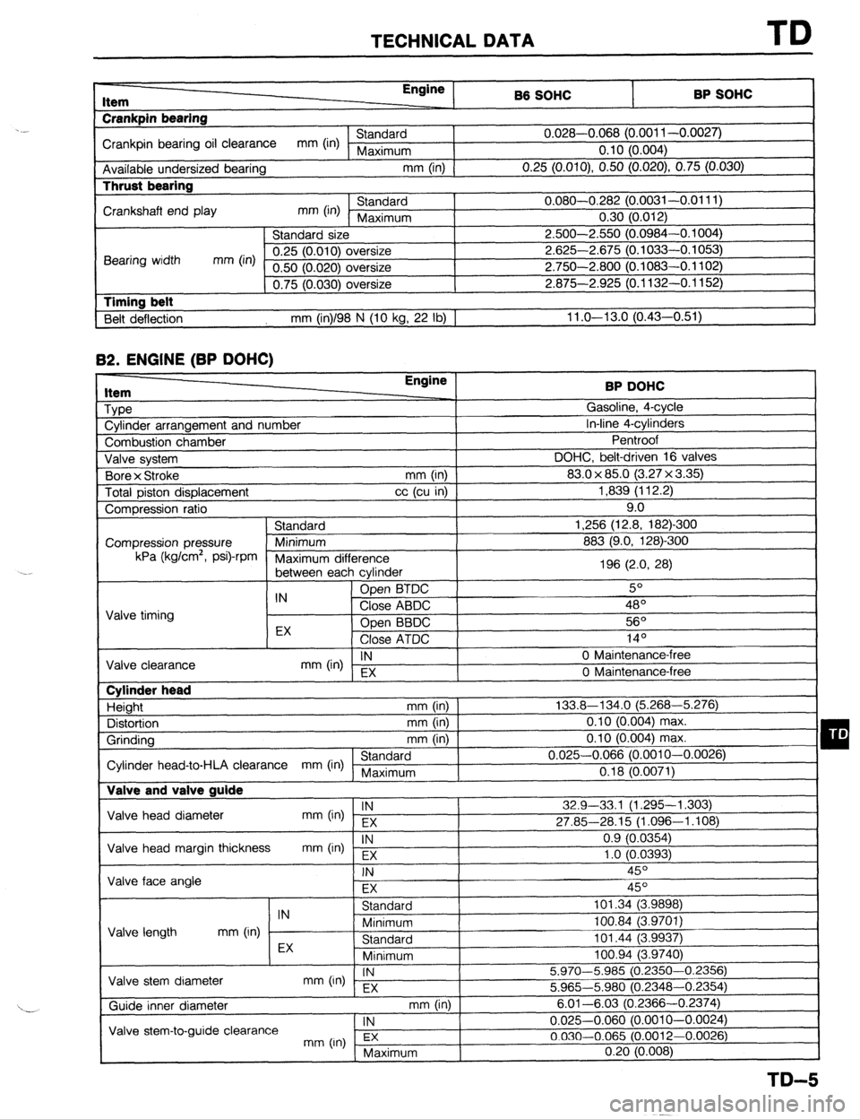
TECHNICAL DATA TD
r-
RP sm.lc: I Item
Crankpin bearing Engine
86 SOHC
I -. VW.._
Crankpin bearing oil clearance mm (in) Standard 0.028-0.068 (0.001 l-0.0027)
Maximum 0.10 (0.004)
Available undersized bearing mm (in)
0.25 (O.OlO), 0.50 (0.020) 0.75 (0.030) Thrust bearing
Crankshaft end play mm (in) Standard 0.080-0.282 (0.0031-0.0111)
Maximum 0.30 (0.012)
Standard size 2.500-2.550 (0.0984-0.1004)
Bearing width mm (in) 0.25 (0.010) oversize 2.625-2.675 (0.1033-0.1053)
0.50 (0.020) oversize 2.750-2.800 (0.1083-0.1102)
0.75 (0.030) oversize 2.875-2.925 (0.1132-0.1152)
1 Timing belt
Belt deflection mm (in)/98 N (10 kg, 22 lb) 1 11 .o-13.0 (0.43-0.51) 82.
ENGINE (BP DOHC) Item
Type
Cylinder arrangement and number BP DOHC
Gasoline, 4-cycle
In-line 4-cylinders
-. I
Combustion chamber
Valve svstem DOHC, belt-d
Bore x Stroke
Total piston displacement ventroot
riven
(3.2:
mm (in) 1 83.0 x 85.0
cc (cu in) ]
7x3.35)1 1,839 (112.2)
I 16 valves I 9.0
-300
mn Compression ratio
Standard 1,256 (12.8, 182)
Compression pressure Minimum 883 (9.0, 128)-Z kPa (kglcm2,
Psi)-rPm
Maximum dif
‘ference
between eat -, h cvlinder 196 (2.0, 28)
IN Open BTDC 5O
Valve timing Close ABDC 48’
EX Open BBDC 56O
Close ATDC .4 In
IY-
IN
mm (in) EX 0 Maintenance-l
Valve clearance
0 Maintenance-i ‘ree
‘me Cylinder head
Height mm (in)
Distortion mm (in)
Grinding mm (in)
Standard
Cylinder head-to-HLA clearance mm (in) Maximum Valve and valve guide 133.8-134.0 (5.268-5.276)
0.10 (0.004) max.
0.10 (0.004) max.
0.025-0.066 (0.0010-0.0026)
0.18 (0.0071)
Valve head diameter IN
mm (in) EX 32.9-33,l (1.295-l ,303)
27.85-28.15 (1.096-1.108)
Valve head margin thickness IN
mm On) Fx 0.9 (0.0354)
1 .o fO.0393)
1 Valve face angle . .
I
FX I I
Valve length IN
Standard 101.34 (3.9898)
mm (in) Minimum 100.84 (3.9701)
Standard 101.44 (3.9937) I -, .
I
Valve stem diameter EX
Minimum loo.94 i3.974oj
IN
mm (in) - EX 5.970-5.985 (0.2350-0.2356)
5.965-5.980 (0.2348-0.2354)
mm (in) I
. , , 6.01-6.03 (0.23 166-0.2374)
1 IN
I 0.025-0.060 (0.0010-0.0024)
3.0012-0.0026)
( Maximum 0.20 (0.008)
I
TD-5
Page 1020 of 1164
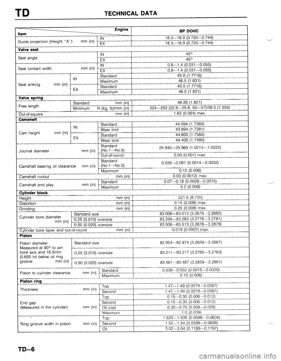
TD TECHNICAL DATA
Item Engine
BP DOHC
Guide projection (Height “A”) IN
mm (in) EX 18.3-l 8.9 (0.720-0.744)
_-j
18.3-l 8.9 (0.720-0.744)
Valve seat
Seat angle
Seat contact width IN 45O
EX 45O
IN
mm (in) EX 0.8-l .4 (0.031-0.055)
0.8-l .4 (0.031-0.055)
Seat sinking
Valve spring
Free length
Out-of-square
Camshaft IN Standard 45.0 (1.7716)
mm (in) Maximum 46.5 (1.831)
EX Standard 45.0 (1.7716)
Maximum 46.5 (1.831)
Standard mm (in) 46.26 (1.821)
Minimum N (kg, Ib)/mm (in) 224-253 (22.8-25.8, 50--57)/39.5 (1.555)
mm (in) 1.62 (0.064) max.
I C+^~rl^.A
44.094 (1.7360)
43.894 (1.7281)
44.600 (1.7560)
44.400 (1.7480) IN 3Ldl l”dl u
Cam height mm (in) Wear limit
EX Standard
Wear limit
Standard
Journal diameter mm (in) (No.l-No.5) 25.940-25.965 (1.0213-l .0222)
Out-of-round 0.03 (0.001) max.
Standard
Camshaft bearing oil clearance mm (in) (No-1-No.5) 0.035-0.081 (0.0014-0.0032)
Maximum 0.15 (0.006)
Camshaft runout mm (in) 0.03 (0.0012) ma
IX.
Camshaft end play mm (in) ’ Standard 0.07-O. 19 (0.0028-0.0075)
Maximum I
I n 9 m mm “.L \“.“““,
Cylinder block
Height
Distortion
Grinding mm (in) 221.5 (8.720)
mm (in) 0.15 (0.006) max.
mm (in) 0.20 (0.008) max.
Cylinder bore diameter Standard size 83.006-83.013 (3.2679-3.2682)
mm (in) 0.25 (0.010) c oversize 83.256-83.263 (3.2778-3.2781)
n.vl IO0701 I -.--
\-----I Jversize 83.506-83.513 (3.2876-3.2879)
Cylinder bore taper and out-of-round mm (in) 0.019 (0.0007) max.
Piston
I
I I
Piston diameter 82.954-82.974 (3.2659-3.2667)
Measured at 90” to pin
bore axis and 16.5mm
83.21 l-83.21 7 (3.2760-3.2763)
(0.650 in) below oil ring
groove
mm fin) 0.50 (0.020) oversize 83.461-83.467 (3.2859-3.2861)
r~ Piston to cylinder clearance
mm On) (Standaid 0.039-0.052 (0.0015-0.0020)
Piston ring
Thickness
End gap
(Measured in the cylinder) mm (in) ‘W
Second
Top
Second
mm (in) Oil (rail)
Maximum
Too I .‘t, - I .ct3 (“.“a, 3-u
1.47-l .49 (0.0579-C
0.1%0:30 (0.006--C
0.15-0.30 (0.006-C
I I.01 2)
0.20-0.70 (0.008-0.028)
1.0 (0.039)
1,520-l
,535 (0.0598-0.0604)
1.52-l .54 (0.0598-0.0606)
3.02-3.04 (0.1189-O. 1197)
I Ring groove width in piston mm (In) n
;_A
TD-6
Page 1021 of 1164
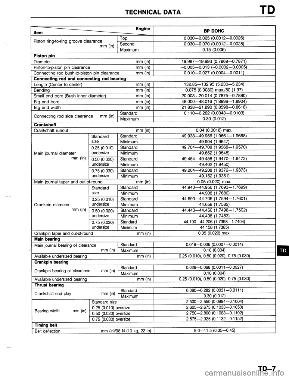
TECHNICAL DATA TD
Item Engine
BP DOHC
?ston ring-to-ring groove clearance Piston pin
3iameter -fop
C----A 0.030-0.065 (0.0012-0.0026)
n n-an n fi7t-i m n
mm (in) imL;UI IU
I “.“a”-“.“, ” \“.~012-0.0026)
Maximum 0.15 (0.006)
mm (in) 19.987-19.993 (0.7869-0.7871)
.0002-0.0005)
~004-0.0011) ‘iston-to-piston pin clearance
Connecting rod bush-to-piston pin clearance Connecting rod and connecting rod bearing
-ength (Center to center)
3ending
Small end bore (Bush inner diameter) mm (in) 1 -0.005-0.013 (-0
mm (in) 1 0.010-0.027 (0.0
I I mm (in) 132.85-132.95 (! 5.230-5.234)
mm (in) 0.075 (0.0030) m lax.150 (1.97)
mm (in) 20.003-20.014 (0.
I , 7875-0.7880)
3ig end bore mm (in) 48.000-48.016 (1.8898-l .8904)
Big end width mm (in) 21.838-21.890 (0.8598-0.8618)
I Cl0nAa.A
Connecting rod side clearance mm (in) I YI’:“‘Yal” 0.11 O-O.262 (0.0043-0.0103)
1 rvraxrmum +
I 0.30 (0.012) Crankshaft
Crankshaft runout mm (in) 0.04 (0.0016) max.
Standard Standard 49.938-49.956 (1.9661-l .9668)
size
Minimum 49.904 (1.9647)
0.25 (0.010) Standard 49.704-49.708 (1.9568-l .9570)
49.652 (1.9548)
Main journal diameter undersize
Minimum
mm (in) 0.50 (0.020) Standard
undersize
Minimum 49.402 (1.9450)
0.75 (0.030) 1 Standard 49.204-49.208 (1.9372-l .9373)
I undersize
I j Minimum
I I
I 49.152 (1.9351)
Main journal taper and out-of-round mm (in) 0.05 (O.OiO) max.
I .7699)
44.908 il.76801
I .7601) Standard Standard
size
Minimum
0.25 (0.010) Standard I 44.940-44.956 (1.7693-l
I
44.690-44.706 il.7594’-1
Crankpin diameter undersize
Minimum 44.658 (1.7582) ’
mm (in) 0.50 (0.020) Standard 44.440-44.456 (1.7496-1.7502) I
undersize I MinimrIm . -. 7 44.408 (1.7483)
0.75 (0.030) Standard 44.190-44.206 (1.7398-l .7404)
undersize
Minimum 44.158 (1.7385)
Crankpin taper and out-of-round mm (in) j 0.05 (0.020) max. Main bearing
Main journal bearing oil clearance Standard 0.018-0.036 (0.0007-0.0014)
mm (in) Maximum 0.10 (0.004)
-m I)
Available undersized bearing mm (in) 0.25 (0.010) 0.50 (0.020) 0.75 (0.030) Crankpin bearing
Crankpin bearing oil clearance
bearing 3Lalluaru
mm (in) .,-..:--..-
Available undersized Thrust bearing I mL^^A^--I
I rvraxrmurTr
mm (in)
Crankshaft end play 0.028-0.068 (0.001 I-0.0027)
0.10 (0.004)
0.25 (O.OlO), 0.50 (0.020) 0.75 (0.030)
Ct-Y.TdQ*A 0.080-0.282 (0.0031-0.0111) ..- -.
0.30 (0.012) I
Standard si7e _._.._
-. - _.-- 2.500-2.550 (0.0984-o. 1004)
Cl c)C In n+A\ nthysize
2.625-2.675 (0.1033-O. 1053)
?rsize 2.750-2.800 ,
(0.1083-0.1102)
0.75 (0.030) oversize 2.875-2.925 (0.1132-0.1152) mm (in) I- Bearing width Timing belt
Belt deflection mm (in)/98 N (10 kg, 22 lb) 1 9.0-l 1.5 (0.35-0.45)
TD-7