1992 MAZDA PROTEGE warning light
[x] Cancel search: warning lightPage 870 of 1164

T FUSE AND JOINT BOX
Specifications (Cont’d)
Fuse Color
METER 15A Blue
WIPER 20A Yellow
STOP 20A Yellow
TAIL 15A
Blue
SUNROOF 15A Blue
DEFOG 20A Yellow
HEATER 30A Light green Protected circuit Instrument panel (gauges and warning lamps), Back-up light, Turn signal,
Cruise control system
Windshield wiper and washer
Stoplight, Horn
Taillight, Side marker light, Parking light, Illumination light, License plate light
Sunroof
Rear window defroster
Blower motor
13UOTX-067
L
r 03UOTX-01
1 BL
PULLER
t
L 03UOTX-01
CIRCUIT
BREAKER
RESET BUTTON
03UOTX.01
Removal / Installation
Main fuse
1. Remove the main fuse box mounting bolts.
2. Open the main fuse box lid and remove the bolt.
3. Remove MAIN 80A fuse.
4. Install in the reverse order of removal.
Fuse
When replacing a fuse, use the fuse puller supplied in the fuse
box cover.
CIRCUIT BREAKER
Note
l Push button to reset circuit breaker after operating
dlagnosls of malfunction.
5
T-14
Page 885 of 1164

EXTERIOR LIGHTING SYSTEM T
EXTERIOR LIGHTING SYSTEM
STRUCTURAL VIEW
13UOTX-02
1. Headlight 5. License plate light
Troubleshooting .......................... page T-30 Troubleshooting .......................... page T-37
Removal / Installation .................. page T-41 Removal / Inspection I
Aiming ......................................... page T-30 Installation ................................. page T-47
2. Front combination light 6. Back-up light switch
Removal / Installation .................. page T-41 Inspection ................................... page T-47
(1) Turn and hazard warning light 7. Flasher unit
Troubleshooting .................... page T-34 Inspection ................................... page T-42
(2) Small light control system 8. High-mount stoplight
Troubleshooting .................... page T-37 Removal / Inspection /
3. Rear combination light Installation ................................. page T-45
Removal / Installation .................. page T-43 9. Rear side marker light
Disassembly I Assembly ............. page T-44 Removal / Installation .................. page T-48
(1) Turn and hazard warning light 10. Daytime running light (DRL) system
Troubleshooting .................... page T-34 Troubleshooting .......................... page T-33
(2) Parking light control system Inspection ................................... page T-42
Troubleshooting .................... page T-37 11. DRL resistor
(3) Stoplight Removal I Installation .................. page T-46
Troubleshooting .................... page T-39 Inspection ................................... page T-46
4. Stoplight switch
Inspection ................................... page T-47
T-29
Page 890 of 1164

EXTERIOR LIGHTING SYSTEM
Turn and Hazard Warning Light
Circuit diagram
BTURN 6; HAZARD FLASHER LIGHTS F-l
BLUE3 TRADE NUMBER
FRONT TURN: 1157 (27W)
REAR TURN : 1156 (27W)
HAZARD SWITCH
ILLUMINATION LAMP:
REFER TO SECTION I-4
-01 TURN SWITCH (F) F-02 FLASHER UNIT (F)
I=] (++&I+YI [ml
WITH CHlJISE CONTROL
WITHOUT CRUISE
CONTROL
-05 HAZARD SWITCH (I) E-12 REAR TURN L$“1’ E-13 REAR TURN ‘R$-$
B R/B
G
03UOTX-052
T-34
Page 892 of 1164

I
EXTERIOR LIGHTING SYSTEM
Only hazard function does not operate
Check the hazard warning Replace the hazard switch
1 I
1 OK
Confirm continuity on B wire of the hazard switch to
ground Repair harness (Hazard switch - Body ground)
OK
I I
Push the hazard switch to activate
OK -2
Confirm continuity on B wire of the flasher unit to body
ground NG
Repair harness (Flasher unit - Hazard switch)
OK
NG
Check the flasher unit (Refer
Replace the flasher unit
Normal
I
Only one side of signal operates
13UOTX-026 .,
Check the turn signal switch
(Refer to page T-27 or T-28)
I Replace the turn switch
1 OK
Turn ignition switch to ON. Turn the signal switch to
defective side
Repair harness (Turn switch - Flasher unit)
Replace the flasher unit
Confirm battery voltage on G/W (G/B) wire of the turn
signal light NG-
- Repair harness (Flasher unit - Turn signal light)
I OK
Confirm continuity on B wire of the turn signal light to
ground NG
Repair harness (Turn signal light - Body ground)
Replace the bulb
T-36
I OK
23UOTX-021
Page 913 of 1164

CENTRAL PROCESSING UNIT (CPU) T
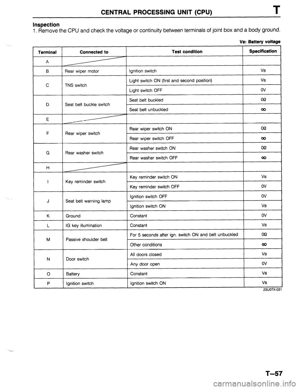
Inspection
1. Remove the CPU and check the voltage or continuity between terminals of joint box and a body ground.
Ve: Battery voltage
Terminal
A Connected to Test condition Specification
B Rear wiper motor Ignition switch
Va
Light switch ON (first and second position) V0
C TNS switch
Light switch OFF ov
Seat belt buckled Ofi
D Seat belt buckle switch
Seat belt unbuckled
co
E
Rear wiper switch ON
OCI
F
Rear wiper switch
Rear wiper switch OFF
co
Rear washer switch ON 00
G Rear washer switch
Rear washer switch OFF
00
H
Key reminder switch ON
Va
I Key reminder switch
Key reminder switch OFF
ov
Ignition switch OFF ov
J Seat belt warning lamp
Ignition switch ON
VB
K Ground Constant
ov
L IG key illumination Constant
VB
For 5 seconds after ign. switch ON and belt unbuckled
00
M Passive shoulder belt
Other conditions
00
All doors closed
Va
N Door switch
Any door open
ov
0 Battery Constant VB
P Ignition switch
ignition switch ON V0
23UOTX-031
T-57
Page 915 of 1164

WARNING SYSTEM
Light-off reminder alarm does not sound.
VB: Battery voltage
Terminal Connected to Test condition Specification To correct
C Headlight switch Headlight switch ON VB Check headlight switch and
wiring harness
(Refer to pages T-27, 28)
P Ignition switch Ignition switch ON VB Check ignition switch and
wiring harness
(Refer to page T-21)
N Door switch Any door open ov Check door switches and
All doors closed V0 wiring harness
(Refer to page T-51)
23UOTX-033
Seat belt alarm does not sound.
VB: Battery voltage
Terminal Connected to Test condition Specification To correct
P ignition switch Ignition switch ON
Vs Check ignition switch and
wiring harness
(Refer to page T-21)
D Seat belt buckle switch Seat belt buckled
00 Check seat belt buckle switch
Seat belt unbuckled
00 and wiring harness
(Refer to page S-102)
23UOTX-034
Seat belt timer does not operate.
VB: Battery voltage
Terminal Connected to Test condition Specification To correct
P Ignition switch Ignition switch ON VE Check ignition switch and
wiring harness
(Refer to page T-21)
23UOTX-035
Passive shoulder belt alarm does not sound.
VB: Battery voltage
Connected to Test condition
Ignition switch Ignition switch Specification
VB
Passive shoulder belt
control unit For 5 seconds after
ignition switch and belt
unbuckled
Other conditions 00
co
IG key illumination timer does not operate.
To correct
I
Check ignition switch and
wiring harness
(Refer to page T-21)
Check passive shoulder belt
control unit and wiring harness
(Refer to page S-104)
23UOTX-036
Ve: Battery voltage
Terminal Connected to Test condition Specification To correct
L IG key illumination Either door open
VB Check bulbs and wiring
harness
N Door switch Any door open ov Check door switches and
All doors closed
VB wiring harness
(Refer to page T-51)
23UOTX-037
T-59
Page 1034 of 1164

TD TECHNICAL DATA
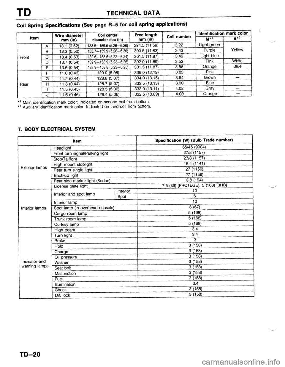
Coil Spring Specifications (See page R-5 for coil spring applications)
*’ Main identification mark color: Indicated on second coil from bottom. l * Auxiliary identification mark color: Indicated on third coil from bottom.
T. BODY ELECTRICAL SYSTEM
Item
Headlight
Frnnt tl wn sinnnl/Pnrkinn linht
Specification (W) (Bulb Trade number)
65145 (9004)
2718 II I 571
I
“‘VW, I u”“y’ 1. I” \’ ‘V’,
uinh mount stoplight 18.4 (1141)
turn single light 27 (1156)
Y-,-~p light 27 (1156)
Rear side marker light (Sedan) 3.8 (194)
License plate light 7.5 (89) [PROTEGE], 5 (168) [3HBl
Interior 10
Interior and spot lamp
spot 6
Interior lamp 10
‘i--” Spot lamp (in overhead console)
8 (67)
Cargo room lamp 5 (168)
Trunk room lamp 5 (168)
I I
ntminr Iamnc
I
Curtesy lamp
High beam
Turn light
Brake
Hold
) Charge 5 (168)
3.4
3.4
3
3 (158)
i
Oil pressure
Washer
Seat belt
Malfunction
Fuel
illumination 3 (158)
3 (158)
3 (158)
3 (158)
3 (158)
3 (158)
3.4 Indicator and
warning lamps
Check 3 (158)
Dif. lock
I 3 (158) .-
,
-.-’
I
I
TD-20
Page 1051 of 1164

PARTS
DIFFERENTIAL ..................................... Jl-52
SHIFT MECHANISM ............................. Jl-56
TRANSAXLE ............................................ Jl-8
TRANSAXLE OIL .................................... Jl-7
MANUAL TRANSAXLE (G5M-R) .................. J2-2
DIFFERENTIAL ..................................... J2-43
SHIFT MECHANISM ............................. J2-46
TRANSAXLE.. .......................................... J2-8
TRANSAXLE OIL .................................... J2-7
MOLDING, PROTECTOR, GARNISH ...........
S-42
BELTLINE MOLDING ............................. S-48
REAR WINDOW MOLDING.. ............. S-43,44
ROOF MOLDING.. .................................. S-46
SIDE PROTECTOR ................................. S-49
UPPER WINDSHIELD MOLDING,
A-PILLAR GARNISH ............................ S-42
NEUTRAL SWITCH (MTX) . . . . . . . . . . . . . . . . . . . . . . . . . . F-l 73
0
1
\_ OIL COOLER (ENGINE). ................................ D-8
OIL PAN (ENGINE) ........................................ D-9
OIL PUMP (ENGINE) ................................... D-l 3
..................................... F-l 71
OXYGEN SENSOR
P
PARKING BRAKE ......................................... P-31
PARKING BRAKE CABLE ............................ P-32
PARKING BRAKE LEVER ............................ P-33
PARKING BRAKE SHOE ............................. P-31
PASSIVE SHOULDER BELT SYSTEM.. ..... S-103
DOOR CATCH SWITCH ....................... S-l 07
LIMIT SWITCH ...................................... S-l 07
PASSIVE SHOULDER BELT MOTOR.. S-106
SPEED SENSOR ................................... S-l 07
WARNING SWITCH .............................. S-l 07
PCV VALVE ................................................
POWER BRAKE UNIT ‘;--=I;;
..................................
POWER DOOR LOCK SYSTEM ................... S-23
DOOR LOCK CONTROL.. ...................... S-26
DOOR LOCK SWITCH.. .......................... S-26
DOOR LOCK TIMER AND RELAY.. ....... S-26
POWER STEERING.. .................................... N-23
POWER STEERING FLUID .......................... N-27
POWER STEERING OIL PUMP.. ................. N-37
POWER STEERING PRESSURE SWITCH . . F-l 73
POWER WINDOW SYSTEM.. .......................
S-27
MAIN POWER WINDOW SWITCH.. .......
S-31
POWER WINDOW MOTOR.. ..................
S-32
POWER WINDOW SUB-SWITCH ........... S-32
PRESSURE REGULATOR (FUEL). ............. F-l 29 . . . . . . . . , . . . . . , . RADIATOR CAP .............................................
E-7
RADIATOR GRILLE,
I
LOWER GRILLE MOLDING ....................... S-51 fl
RADIATOR THERMOSWITCH ...................... E-17 t
REAR AXLE ................................................. M-10
REAR BRAKE (DISC) ................................... P-23
REAR BRAKE (DRUM) ................................. P-28
REAR BUMPER ............................................ s-40
REAR COMBINATION LIGHT.. ....
REAR CROSSMEMBER ............................... R-29
REAR DOOR ................................................ S-l 5
REAR DOOR LOCK AND OPENER.. .
REAR FINISHER ........................................... s-52
REAR HATCH ............................................... s-20
REAR HATCH LOCK AND OPENER.. ......... S-22
REAR SHOCK ABSORBER AND SPRING.. R-21
REAR SIDE MARKER LIGHT ....................... T-48
REAR SIDE WINDOW REGULATOR AND . . . . . . . . .
AI .,.n
INDEX
Q
QUARTER WINDOW GLASS . . . . . . . . . . . . ..a........ S-62
R
RADIATOR . . . . . . . . . . . . . . . . . . . . . . . . . . . . . . . . . . . . . . . . . . . . . . . . . . . . . .
kiLA33 ........................................................ a-- I I
REAR SPEAKER ........................................... T-99
REAR SPOILER ............................................ s-41
REAR STABILIZER.. ..................................... R-27
REAR SUSPENSION .................................... R-20
REAR WINDOW GLASS ............................... S-63
REAR WINDOW DEFROSTER.. .................... T-74
REAR WINDOW DEFROSTER SWITCH ....... T-77
REAR WIPER AND WASHER ...................... S-74
REAR WASHER MOTOF
REAR WIPER AND WASHER SWITCH . . S-77
REAR WIPER MOTOR ............................ s-77
RELEASE BEARING (CLUTCH). . . . . . . . . . ..s..... H-17 I . . . . . . . . ...*. .*......*..
SEAT BELT.. ........................................ S-100,102
BUCKLE SWITCH.. ............................... S-l 02
SEAT ........................................................... s-110
SEPARATOR (FUEL) .................................. F-l 40
SHUTTER VALVE ACTUATOR (VICS) ........ F-l 18
SLIDING SUNROOF ..................................... S-80
MOTOR ASSEMBLY ............................... S-81
SUNROOF RELAY.. ................................ S-82
SUNROOF SWITCH.. .............................. S-82
SOLENOID VALVE
(PRESSURE REGULATOR CONTROL) .... F-135
SOLENOID VALVE (PURGE CONTROL). .. F-140
SOLENOID VALVE (VICS) .......................... F-l 18
SPARK PLUGS ............................................ G-18
-II__