Page 704 of 1164
WHEELS AND TIRES
WEAR INDICATOR WEAR IbiDICATOR
13UOQX-00s
13UOQX-011 0
23UOQX-004
Tire Wear
1. Check the remaining tread.
Remaining tread
Standard tires: 1.6mm (0.063 in) min.
Snow tires: 50% of tread ’ _,I’
2. The tire should be replaced if the wear indicators are
exposed.
Inspection (Tire and Wheel)
The wheel or tire should be replaced if any crack, damage,
deformation or other problem is found.
Wheel and Tire Runout
1. Jack up the vehicle and place it on safety stands.
2. Set the probe of a dial indicator against the wheel, and meas-
ure the runout through one full revolution.
Runout:
_..’
Horizontal Aluminum wheel: 2.0 (0.079), Steel wheel: 2.5 (0.098)
Vertical 1.5 (0.059)
3. Replace the wheel if necessary.
Caution
l Adjust wheel balance after replacement of a wheel
or tire.
Lug Nut
1. Verify that the lug nuts are tightened to the specified torque.
Tightening torque:
66-l 16 N*m (9-12 m-kg, 65-67 ft-lb)
Q-4
Page 705 of 1164
WHEELS AND TIRES
Irregular Tire Wear
Abnormal tire wear patterns, such as shown in the illustration, may occur. Refer to the chart for the possible
causes and remedies.
Wear condition
SHOULDER WEAR Possible cause l Underinflation (both sides worn) l Hard cornering l Lack of rotation Remedy
l Measure and adjust pressure l Reduce speed l Rotate tires
CENTER WEAR
l Overinflation l Lack of rotation *Measure and adjust pressure l Rotate tires
FEATHERED EDGE
l Incorrect toe adjustment l Adjust toe-in
UNEVEN WEAR
l Incorrect camber or caster l Malfunctioning suspension l Unbalanced wheel
*Out-of-round brake drum or disc
l Lack of rotation *Repair or replace axle or suspension parts
l Repair or replace suspension l Balance or replace
*Correct or replace
l Rotate tires
03UOQX-01
Q-5
Page 706 of 1164

WHEELS AND TIRES
L 13UOQX-005
FRONT
13UOQX-006
G=a I) OUTSIDE
BALANC
WEIGHT
REMOVAL / INSTALLATION
1. The wheel-to-hub contact surfaces must be clean.
2. Tighten the lug nuts to the specified torque.
Tightening torque:
88-l 18 N-m (9-12 m-kg, 85-87 ft-lb)
Caution
l When reinstalling a wheel, retighten the lug nuts to
the specified torque after about 1,000 km (820 miles)
driving.
TIRE ROTATION
To prolong tire life and assure uniform tire wear, rotate the tires
from every 3,000 km (1,860 miles) to every 6,000 km (3,720
miles).
Caution
l Do not include “TEMPORARY USE ONLY” spare tire
in rotation.
l Use the best tires on the front axle.
l After rotating the tires, adjust each tire to the speci-
fied air pressure. (Refer to page Q-3.)
WHEEL BALANCE ADJUSTMENT
If a wheel becomes unbalanced or if a tire is replaced or
repaired, the wheel must be rebalanced to within specification.
Maximum unbalance (at rim edge)
13 inch wheel: 11 g (0.39 oz)
14 inch wheel: 10 g (0.35 or)
Caution
l Do not use more than two balance weights on the
inner or outer side of the wheel.
l If the total weight exceeds 1OOg (3.5 oz) perslde,
rebalance after moving the tire around on the rim.
l Attach the balance weights tightly on the wheel.
l Select suitable balance weights for steel or alumi-
num alloy wheels.
l Do not use an on-car balancer on automatic trans-
axle models; it may cause transaxle damage.
.__’
Q-6
Page 735 of 1164

REAR CROSSMEMBER
Removal / Installation
REAR SUSPENSION (STRUT) R
1. Jack up the vehicle and support it with safety stands.
2. Remove the wheels and tires.
3. Remove the brake pipe holder.
4. Remove in the order shown in the figure.
5. Inspect all parts and repair or replace as necessary.
6. Install in the reverse order of removal, referring to
Installation Note.
7. After installation, check the rear wheel alignment and adjust it if necessary.
Caution
l Loosely tighten the lateral link and trailing link bolts and nuts when installing. Lower the vehi-
cle and tighten all nuts and bolts to the specified torques with the vehicle unladen.
46-63 (4.7-6.4, 34-46)
66-117 (6.7-11.9, 63-66)
I
66-95 (W-9.7,
43-59 (4.4-6.0, 32-43)
63-93 (6.4-9.5, 46-69)
N.m (m-kg, ft-lb)
‘)‘)I ano” n,
1. Nut (Stabilizer)
Installation Note . . . . . . . . . . . . . . . . . . . . . . . . . .
2. Bushing and retainer
3. Bolt, retainer and bushing
4. Retainer, bushing and spacer
5. Bolt (Lateral link)
6. Bolt (Trailing link)
7. Bolt (Trailing link) 8. Trailing link
page R-28 9. Bolt (Lateral link)
10. Lateral link (front and rear)
Il. Bolt
12. Rear stabilizer
13. Bolt and washer
14. Rear crossmember
R-29
Page 1015 of 1164

TD
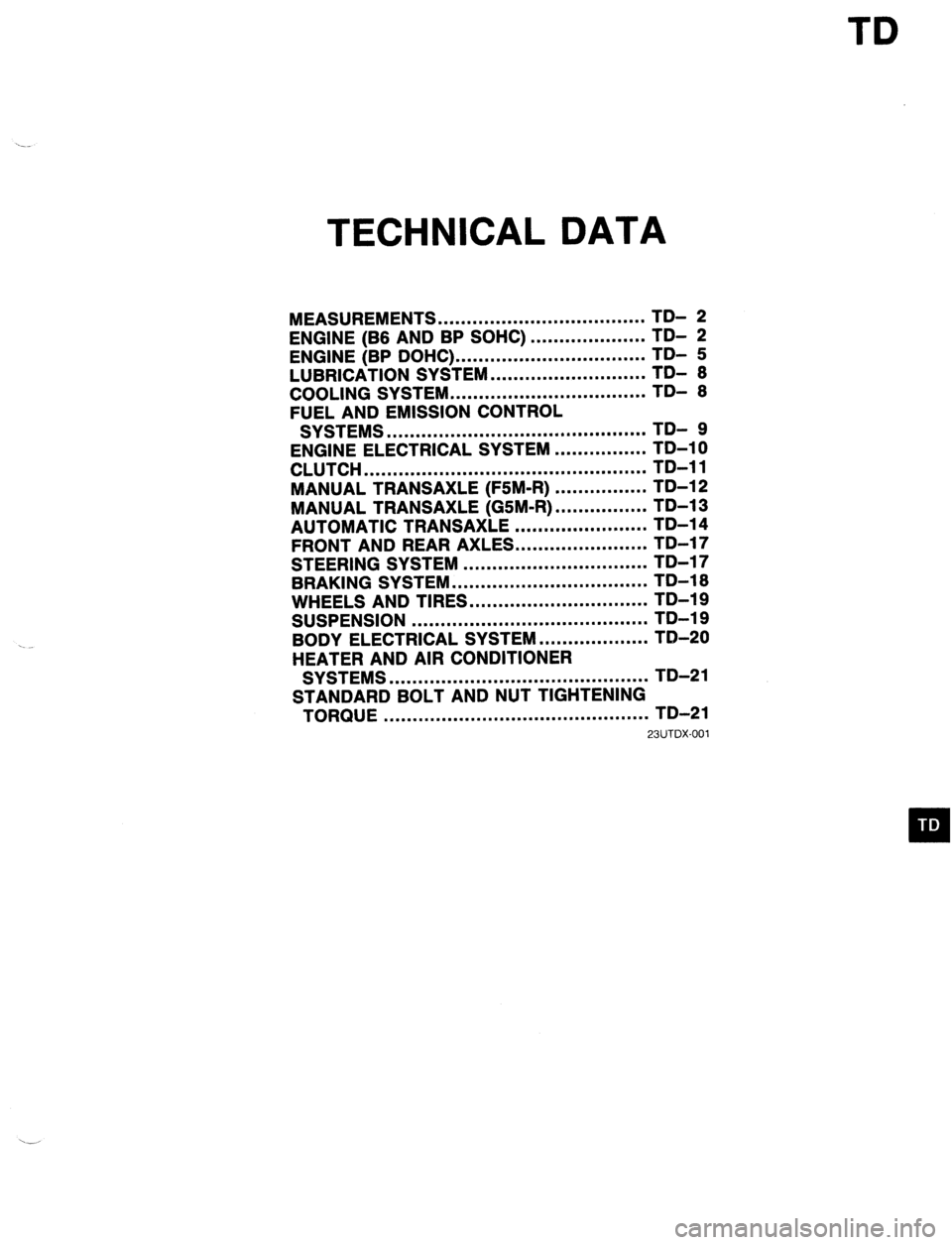
TECHNICAL DATA
MEASUREMENTS .................................... TD- 2
ENGINE (B6 AND BP SOHC)
ENGINE (BP DOHC) ... .................................................. ;;- f
LUBRICATION SYSTEM ........................... TDI 6
COOLING SYSTEM .................................. TD- 6
FUEL AND EMISSION CONTROL
SYSTEMS ............................................. TD- 9
ENGINE ELECTRICAL SYSTEM ................ TD-10
CLUTCH ................................................. TD-11
MANUAL TRANSAXLE (F5M-R) ................ TD-12
MANUAL TRANSAXLE (GSM-R) ................ TD-13
AUTOMATIC TRANSAXLE ....................... TD-14
FRONT AND REAR AXLES.. .....................
STEERING SYSTEM ................................ ;;-;;
-
BRAKING SYSTEM .................................. TD-16
WHEELS AND TIRES ............................... TD-19
SUSPENSION ......................................... TD-19
BODY ELECTRICAL SYSTEM ................... TD-20
HEATER AND AIR CONDITIONER
SYSTEMS ............................................. TD-21
STANDARD BOLT AND NUT TIGHTENING
TORQUE .............................................. TD-21
23UTDX-001
Page 1033 of 1164

TECHNICAL DATA
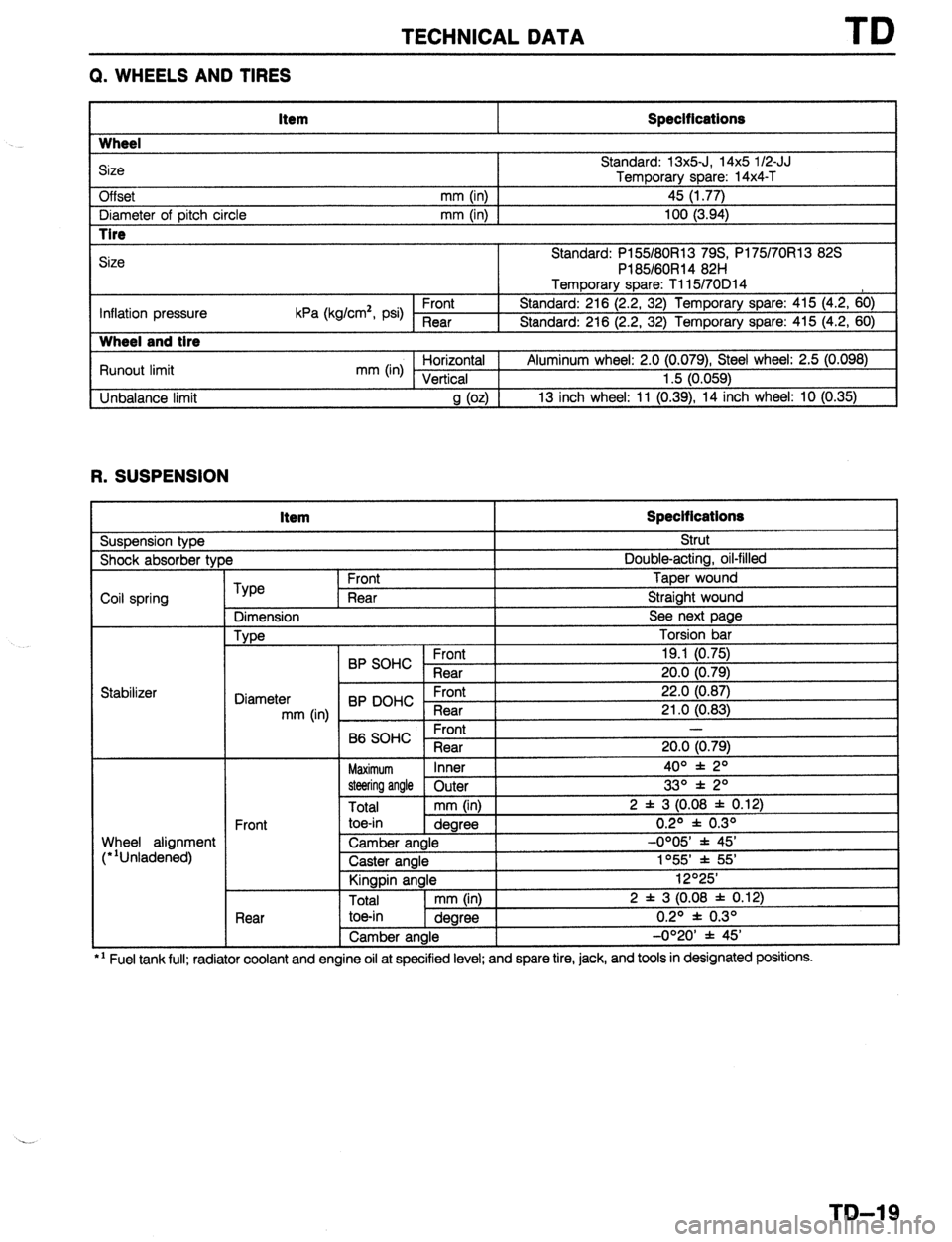
Q. WHEELS AND TIRES
Item Specifications
Wheel
Size
Off set Standard: 13x5-J, 14x5 l/2-JJ
Temporary
mm (in) 1 _ spare: 14x4-T
45 (1.77)
I Diameter of oitch circle
mm (in) I 100 (3.94)
r I Pl
-
Inflation pressure kPa (kg/cm*, psi) Front 1 8
I 9
Runout limit
Unbalance limit mm (in) ;lii.raltLa’
a (02) ’
13 inch wheel: 11 (0.
R. SUSPENSION Item Specifications
Suspension type Strut
)e Double-acting, oil-filled
I Shock absorber tyf
Coil spring
Type
Dimension
Type Front Taper wound
Rear Straight wound
See next page
Torsion bar
I
I C.rrn,
19.1 (0.75)
20.0 (0.79)
22.0 (0.87)
21 .O f0.83)
Wheel alignment
(“‘Unladened) BP SOHC ;;a;
Diameter
mm (in) BP DOHC - ;la;t
Front -
B6 SOHC
Rear 20.0 (0.79)
Maximum Inner 4o” f 2O
steering angle Outer
Total mm (in) 2 f 3 (0.08 j
Front toe-in
dearee
.-.._
Rear
.--. I --- ~~
Camber angle
Caster angle
Kingpin angle
I Total
I mm OnI I I toe-in
1 dearee I , --U’-- 1
Camber angle
I 33O * 2O
: 0.12)
0.2O f 0.3O
-0OO5’ * 45’
1055’ * 55’
12O25’
2 f 3 (0.08 f 0.12)
0.2O f 0.3O
-0°20’ f 45’
l ’ Fuel tank full; radiator coolant and engine ail at specified level; and spare tire, jack, and tools in designated posmons.
TD-19
Page 1052 of 1164

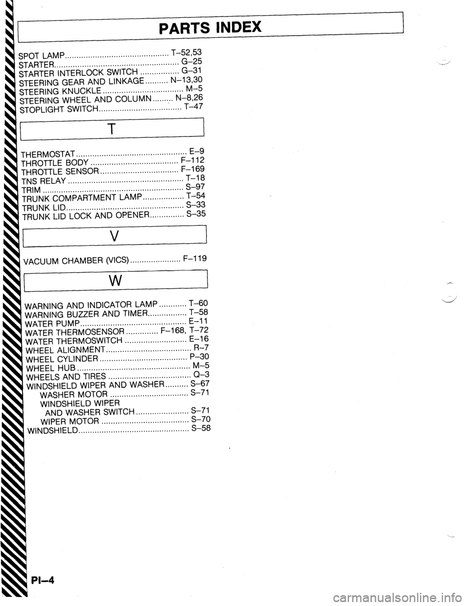
01 LAMP.., ., ,..... . . . . . . 9.. a.. . . . 9.e.. . . . . . . . . . . . . . . T-5233
ARTER .,,.,..,..,..,,....,..,......,........................ G-25
RTER INTERLOCK SWITCH .,............... G-31
ERING GEAR AND LINKAGE . . . . . . . . . . N-13,30
ERING KNUCKLE . . . . . . . . . . . . . . . . . . . . . . . . . . . . . . . . . . . M-5
TEERING WHEEL AND COLUMN . . . . . . . ,.. N-8,26
WITCH . . . . . . . . . . . . ..I..................... T-47
THERMOSTAT . . . . . ,.,..,......,.. . . . . . . . . . . . . . . . . . . . ..a..... . E-9
THROTTLE BODY . . . . . . . . . . . . . . . . . ..s............. . . . . . F-l 12
THROTTLE SENSOR .., . . . . . . . . . s............. . . . . . . . . F-l 69
TNS RELAY . . . . . . . . . . . . . . . . . . . . . . . . . . . . . . . . . . . . . . . . . . . . . . . . . . T-18
TRIM . . . . . . . . . . . . . . . . . . . . . . . . . . . . . . . . . . . . . . . . . . . . . . . . . . . . . . . . . . . . . S-97
TRUNK COMPARTMENT LAMP . . . . . . . . . . ..a..... T-54
TRUNK LID ,,.,...........,................................... S-33
TRUNK LID LOCK AND OPENER a.............. S-35
VACUUM CHAMBER (VICS) . . . . . . . . . . . . . . ..s..... F-l 19
AND INDICATOR LAMP . ..a........ T-60
BUZZER
AND TIMER . . . . . . . . . . . . . . . . . T-58
MP . . . . . . . . . . . . . . . . . . . . . . . . . . . . . . . . . . . . . . . . . . . . . . E-l 1
THERMOSENSOR s..........,.. F-l 68, T-72
THERMOSWITCH ..,,....................... E-l 6
ALIGNMENT . . . . . . . . . . . . . . . . . . . . . . . . . . . . . . . . . . . . . R-7
HEEL CYLINDER ,.............,..,.................... P-30
HEEL HUB .r,....,......................................... M-5
HEELS AND TIRES . . . . . . . . . . . . . . . . . . . . . . . . . . . . . . . . . . . . Q-3
INDSHIELD WIPER AND WASHER . . . . . . . . . . S-67
WASHER MOTOR ,.......,..,...................... S-71
WINDSHIELD WIPER
AND WASHER SWITCH s............,......... S-71
WIPER MOTOR ,....,,............................... S-70
INDSHIELD .,.......,.....,..,....,,....................... S-58