1992 MAZDA PROTEGE check engine
[x] Cancel search: check enginePage 993 of 1164

AIR CONDITIONER U / ,
9MUOUX-13
SIGHT GLASS
Checking refrigerant charge
1. Run the engine at a fast idle.
2. Operate the air conditioner at maximum cooling for a few
minutes.
3. Determine the amount of refrigerant as shown below by ob-
serving the sight glass.
Item Symptom Amount of refrigerant Action
I Bubbles present in sight glass Insufficient refrigerant Check refrigerant pressure
2 No bubbles present in sight glass Too much or proper amount of Turn air conditioner OFF, and
refrigerant watch bubbles (Refer to Items 3
and 4)
3 Immediately after air conditioner turned Too much refrigerant Check refrigerant pressure
OFF, refrigerant in sight glass stays clear
4 When air conditioner turned OFF, refrigerant Proper amount of refrigerant Refrigerant amount normal
foams, and then sight glass becomes clear
QMUOUX-140
Checking refrigerant pressure
1. Connect the manifold gauge set. (Refer to page U--32.)
2. Operate the engine at 2,000 rpm and set the air condition-
er to maximum cooling.
3. Measure the low- and high-pressure sides.
Normal pressure
Low-pressure side: 147-294 kPa
(1.5-3.0 kg/cm2, 21-43 psi)
High-pressure side: 1 ,I 77-l ,619 kPa
(12.0-l 6.5 kg/cm2, 171-235 psi)
u-37
Page 996 of 1164

U AIR CONDITIONER
OFF
03UOUX-06
03UOUX-06,
03UOUX-06
On-vehicle Inspection
Thermoswitch
1. Remove the glove box.
2. Run the engine at idle.
3. Turn OFF the A/C switch and set the blower switch to the
highest position to operate the blower fan for a few minutes.
4. After a few minutes, turn OFF the blower switch and stop
the engine.
5. Disconnect the thermoswitch connector and check for con-
tinuity between terminals of the switch.
Terminals Continuity
a-b Yes
6. If not as specified, replace the thermoswitch.
Note
l The thermoswitch contacts will be open if the
evaporator temperature is below 0.4 f 0.7OC (32.7
z!z 1.3OF).
Inspection
Thermoswitch
1. Immerse the sensing bulb in a container of ice water.
2. Check continuity between terminals of the switch as
specified.
Terminals
a-b Temperature Continuity
Above 5°C Yes
Below 0% No
3. If not as specified, replace the thermoswitch
Evaporator
1. Check the evaporator fins for blockage. If the fins are
clogged, clean them with compressed air.
Caution
l Never use water to clean the evaporator.
2. Check the fittings for cracks and other damage.
Replace the evaporator if necessary.
u-40
Page 1011 of 1164
AIR CONDITIONER U
REFRIGERANT PRESSURE
2.0 f 0.2 kg/cm* 27 f 2 kg/cm’
4.1 f 0.5 kg/cm* 21 * 4 kg/cm*
03uoux-09
9
23UOUX-050
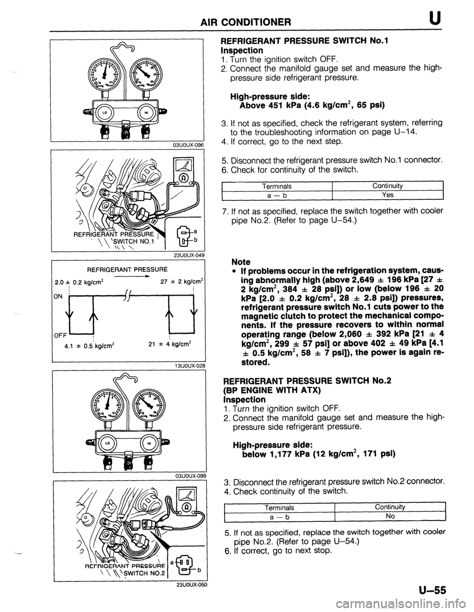
REFRIGERANT PRESSURE SWITCH No.1
Inspection
1. Turn the ignition switch OFF.
2. Connect the manifold gauge set and measure the high-
pressure side refrigerant pressure.
High-pressure side:
Above 451 kPa (4.6 kg/cm2, 65 psi)
3. If not as specified, check the refrigerant system, referring
to the troubleshooting information on page U-14.
4. If correct, go to the next step.
5. Disconnect the refrigerant pressure switch No.1 connector.
6. Check for continuity of the switch.
Terminals
1 Continuity
a-b
Yes I
7. If not as specified, replace the switch together with cooler
pipe No.2. (Refer to page U-54.)
Note
l If problems occur in the refrigeration system, caus-
ing abnormally high (above 2,649 SL: 196 kPa [27 f
2 kg/cm2, 384 f 28 PSI]) or low (below 196 f 20
kPa [2.0 f 0.2 kg/cm2, 28 & 2.8 psi]) pressures,
refrigerant pressure switch No.1 cuts power to the
magnetic clutch to protect the mechanical compo-
nents. If the pressure recovers to within normal
operating range (below 2,080 f 392 kPa [21 f 4
kg/cm2, 299 f 57 psi] or above 402 f. 49 kPa t4.1
f 0.5 kg/cm2, 58 f 7 psi]), the power is again re-
stored.
REFRIGERANT PRESSURE SWITCH No.2
(BP ENGINE WITH ATX)
Inspection
1. Turn the ignition switch OFF.
2. Connect the manifold gauge set and measure the high-
pressure side refrigerant pressure.
High-pressure side:
below 1,177 kPa (12 kg/cm2, 171 psi)
3. Disconnect the refrigerant pressure switch No.2 connector.
4. Check continuity of the switch.
Terminals
a-b I Continuity
No
5. If not as specified, replace the switch together with cooler
pipe No.2. (Refer to page U-54.)
6. If correct, go to next stop.
u-55
Page 1012 of 1164
AIR CONDITIONER
23UOUX-051
23UOUX-05
23UOUX-05
U-56
Caution
l While testing refrigerant pressure switch No.2, care-
fully note the high-pressure side refrigerant pres-
sure. If the pressure increases above 1,766 kPa (18
kg/cm2, 256 psi), stop the testing. _,
7. Disconnect the condenser fan connector.
8. Run the engine at 2,000 rpm, and operate the air condi-
tioner at maximum cooling position.
9. Check that the refrigerant pressure switch turns on when
the high-pressure side refrigerant pressure increases above
1,570 f 98 kPa (16 f 1 kg/cm2, 228 f 14 psi).
IO. If not as specified, replace the switch together with cooler
pipe No.2. (Refer to page U-54.)
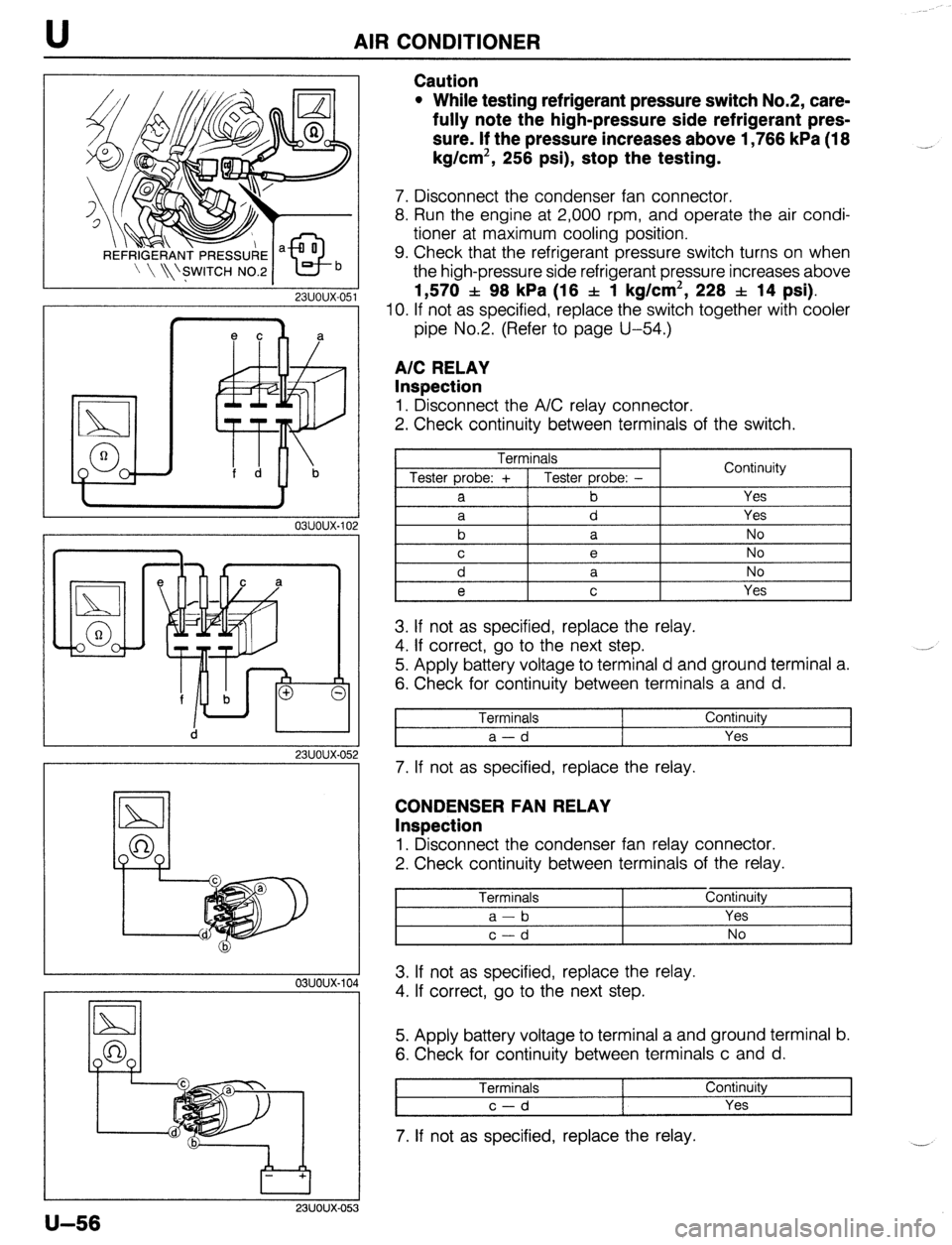
A/C RELAY
Inspection
1. Disconnect the A/C relay connector.
2. Check continuity between terminals of the switch.
Terminals
Tester probe: + 1 Tester probe: -
a b Continuity
Yes
3. If not as specified, replace the relay.
4. If correct, go to the next step.
5. Apply battery voltage to terminal d and ground terminal a.
6. Check for continuity between terminals a and d.
Terminals
a-d Continuity
Yes
7. If not as specified, replace the relay.
CONDENSER FAN RELAY
Inspection
1. Disconnect the condenser fan relay connector.
2. Check continuity between terminals of the relay.
Terminals Continuity
I a-b Yes I
2
I c-d I No I
A 3. If not as specified, replace the relay.
4. If correct, go to the next step.
5. Apply battery voltage to terminal a and ground terminal b.
6. Check for continuity between terminals c and d.
Terminals Continuity
c-d Yes
7. If not as specified, replace the relay.
Page 1022 of 1164
TECHNICAL DATA
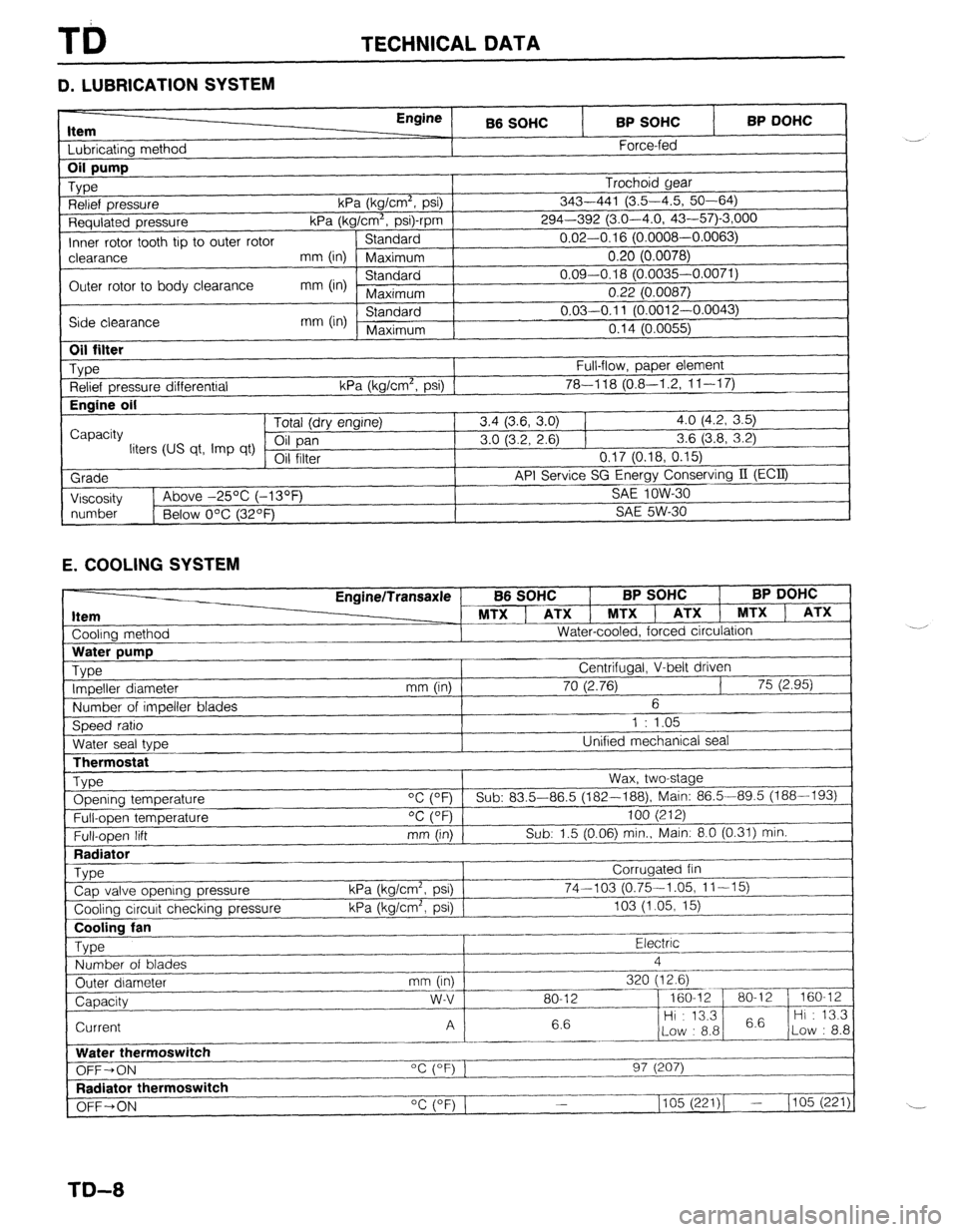
D. LUBRICATION SYSTEM
Item I I bhricatinn mothnd
Engine
B6 SOHC BP SOHC
Force-fed BP DOHC 1
Requlated pressure kPa (kg/Cm”, p
Inner rotor tooth tip to outer rotor Standard
I-‘---- -.----,
clearance mm (in) Maximum 0.20 (0.0078)
Outer rotor to body clearance mm (in) Standard 0.09-0.18 (0.0035-0.0071)
Maximum 0.22 (0.0087)
Side clearance mm (in) Standard 0.03-0.11 (O.pniq n nnn=’
Maximum n4rl ‘-
“” I r-“.““+..I,
I “. I ‘t (U.0055)
I
1
Oil filter
_ Type
Relief pressure differential
Engine oil
I
Capacity
liters (US qt, Imp qt)
Grade
I Viscosity Full-flow, paper element
kPa (kg/cm’, psi) 1 78-l 18 (0.8-I .2, 1 l-l 7) Tntal /An, nnr*inol 3.4 (3.6, 3.0) 1 4.0 (4.2, 3.5)
3.0 (3.2, 2.6) 1 3.6 (3.8, 3.2)
VII 111Lb1 0.17 (0.18, 0.15)
API Service SG Energy Conserving II (ECQ
1
SA!f InW-Xl 1~ Above -25% (-13OF _ .-.. --
I
I
number
1 Below O’C (32OF) SAE 5W-30
1
E. COOLING SYSTEM
Cooling method EnginelTransaxle
MTX ] ATX 1 MTXl
Water-cooled, forced circulation
J B6 SOHC BP SOHC BP DOHC
, ATX 1 MTX ) ATX
LThermostat
Type Opening temperature
Full-open temperature
Full-open lift
Radiator
_ Type
Cap valve opening pressure
Cooling circuit checking pressure Wax, two-stage
“C (OF) Sub: 83.5-86.5 (182--188), Main: 86.5-89.5 (188-193)
OC (OF) 100 (212)
mm (in) Sub: 1.5 (0.06) min., Main: 8.0 (0.31) min.
Corrugated fin
kPa (kg/cm2, psi) 74-103 (0.75-1.05, 11-15)
kPa (kg/cm’, psi) 103 (1.05, 15)
~..
Cooling fan
Type Electric .-
Number of blades 4
_.---- _I___-
Outer diameter mm (in) 320 (12.6)
--_ ~~-
Capacity w-v 80-12 - 160-12 80-l 2 160-12
6.6 Hi : 13.3
6.6 Hi : 13.3
Current A
Low : 8.8 Low : 8.8
_------ ._____
Water thermoswitch
“c (OF) 1
OFF-ON 97 (207)
I--.
Radiator thermoswitch
__-I____-
OFF+ON “C (OF) 1 1105 (221)( - (105 (221)
TD-8
Page 1037 of 1164
SPECIAL TOOLS
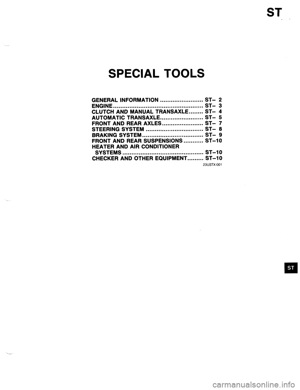
GENERAL INFORMATION ........................
ENGINE .................................................. i;-
- ‘3
CLUTCH AND MANUAL TRANSAXLE.. ...... ST- 4
AUTOMATIC TRANSAXLE.. ...................... ST- 5
FRONT AND REAR AXLES.. ..................... ST- 7
STEERING SYSTEM ................................ ST- 8
BRAKING SYSTEM .................................. ST- 9
FRONT AND REAR SUSPENSIONS.. ......... ST-10
HEATER AND AIR CONDITIONER
SYSTEMS ............................................. ST-l 0
CHECKER AND OTHER EQUIPMENT.. ....... ST-10
23USTX-001
Page 1047 of 1164
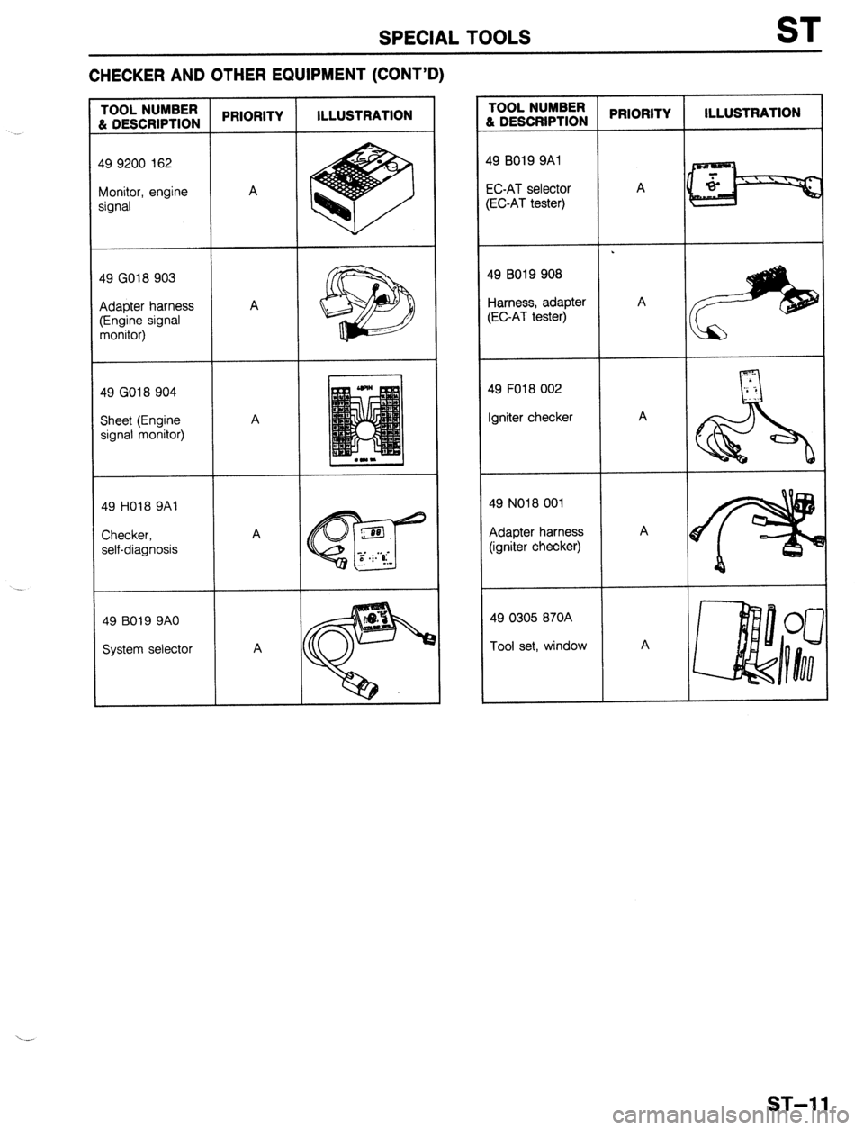
SPECIAL TOOLS ST
CHECKER AND OTHER EQUIPMENT (CONT’D)
49 9200 162
Monitor, engine
49 GO18 903
Adapter harness
49 GO18 904
Sheet (Engine
49 HO18 9Al
49 B019 9AO
System selector TOOL NUMBER
L DESCRIPTION PRIORITY ILLUSTRATION
19 BO19 9Al
X-AT selector
EC-AT tester) A .
19 B019 908
larness, adapter A
;EC-AT tester)
49 FO18 002
Igniter checker A
49 NO18 001
Adapter harness A
(igniter checker)
49 0305 870A
Tool set, window A
ST-l 1
Page 1049 of 1164
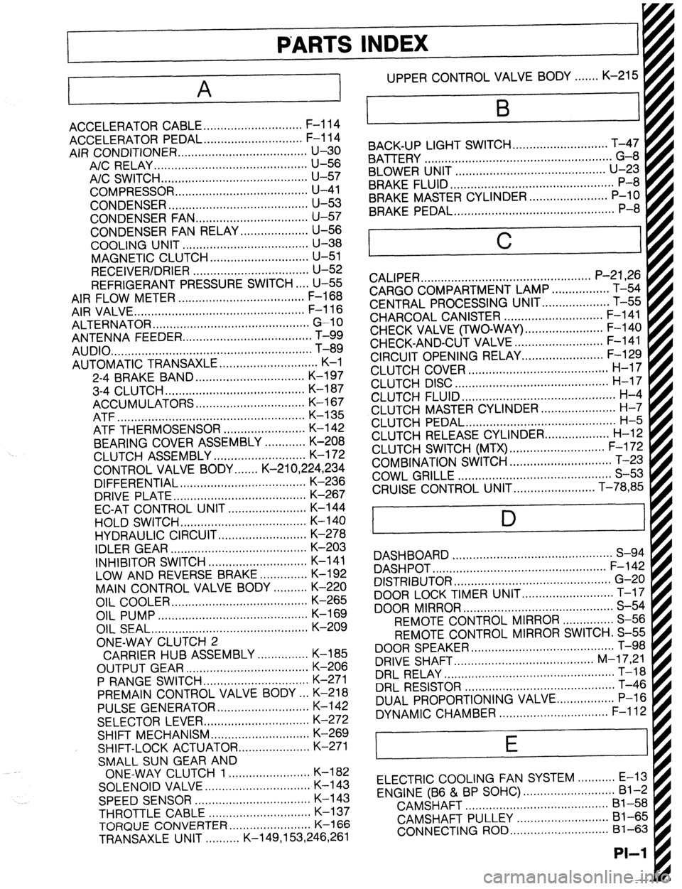
PARTS INDEX
‘I
A
ACCELERATOR CABLE ............................. F-l 14
ACCELERATOR PEDAL ............................. F-l 14
AIR CONDITIONER ...................................... u-30
A/C RELAY.. ........................................... U-56
A/C SWITCH ...........................................
U-57
COMPRESSOR.. ..................................... U-41
CONDENSER.. ....................................... U-53
CONDENSER FAN ................................. u-57
CONDENSER FAN RELAY .................... U-56
COOLING UNIT ..................................... U-38
MAGNETIC CLUTCH ............................. u-51
RECEIVER/DRIER .................................. U-52
REFRIGERANT PRESSURE SWITCH.. .. U-55
AIR FLOW METER ..................................... F-l 68
AIR VALVE.. ................................................ F-l 16
ALTERNATOR .............................................. G-10
ANTENNA FEEDER
AUDIO
....... .......................................................................................... T-i;
AUTOMATIC TRANSAXLE ............................. K-l
2-4 BRAKE BAND ................................ K-l 97
3-4 CLUTCH.. ....................................... K-l 87
ACCUMULATORS ................................ K-l 67
ATF ....................................................... K-135
ATF THERMOSENSOR ........................ K-142
BEARING COVER ASSEMBLY ............ K-208
CLUTCH ASSEMBLY ........................... K-l 72
CONTROL VALVE BODY.. .....
K-21 0,224,234
DIFFERENTIAL ..................................... K-236
DRIVE PLATE.. ..................................... K-267
EC-AT CONTROL UNIT ....................... K-144
HOLD SWITCH ..................................... K-140
HYDRAULIC CIRCUIT .......................... K-278
IDLER GEAR ........................................ K-203
INHIBITOR SWITCH ............................. K-l 41
LOW AND REVERSE BRAKE .............. K-192
MAIN CONTROL VALVE BODY .......... K-220
OIL COOLER.. ...................................... K-265
OIL PUMP ............................................
K-169
OIL SEAL ..............................................
K-209
ONE-WAY CLUTCH 2
CARRIER HUB ASSEMBLY ............... K-185
OUTPUT GEAR .................................... K-206
P RANGE SWITCH.. ............................. K-271
PREMAIN CONTROL VALVE BODY .a. K-218
PULSE GENERATOR ........................... K-142
SELECTOR LEVER ............................... K-272
SHIFT MECHANISM ............................. K-269
SHIFT-LOCK ACTUATOR
..................... K-271
SMALL SUN GEAR AND
ONE-WAY CLUTCH 1 ........................ K-l 82
SOLENOID VALVE.. ............................. K-l 43
SPEEDSENSOR .................................. K-l 43
THROTTLE CABLE .............................. K-l 37
TORQlJE CONVERTER.. ...................... K-l 66
TRANSAXLE UNIT. ......... K-149,153,246,261 UPPER CONTROL VALVE BODY.. ..... K-215
BACK-UP LIGHT SWITCH..
..........................
BATTERY T;4;
- .......................................................
BLOWER UNIT ............................................
U-23
BRAKE FLUID.. .............................................. P-8
BRAKE MASTER CYLINDER. ...................... P-10
BRAKE PEDAL ...............................................
P-8
C
CALIPER .................................................. P-21,26
CARGO COMPARTMENT LAMP ................. T-54
CENTRAL PROCESSING UNIT..
.................. T-55
CHARCOAL CANISTER ............................. F-l 41
CHECK VALVE (TWO-WAY) .......................
CHECK-AND-CUT VALVE - .......................... ;-;b$
CIRCUIT OPENING RELAY.. ...................... F-129
CLUTCH COVER ......................................... H-l 7
CLUTCH DISC ............................................. H-l 7
CLUTCH FLUID ............................................. H-4
CLUTCH MASTER CYLINDER.. .................... H-7
CLUTCH PEDAL ............................................ H-5
CLUTCH RELEASE CYLINDER..
................. H-12
CLUTCH SWITCH (MTX) ............................ F-l 72
COMBINATION SWITCH .............................. T-23
COWL GRILLE ............................................. S-53
CRUISE CONTROL UNIT.. ...................... T-78,85
D
DASHBOARD ............................................... S-94
DASHPOT ................................................... F-l 42
DISTRIBUTOR .............................................. G-20
DOOR LOCK TIMER UNIT ........................... T-17
DOOR MIRROR ............................................ S-54
REMOTE CONTROL MIRROR ............... S-56
REMOTE CONTROL MIRROR SWITCH. S-55
DOOR SPEAKER .......................................... T-98
DRIVE SHAFT.. ....................................... M-l 7,21
DRL RELAY.. ................................................ T-18
DRL RESISTOR ............................................ T-46
DUAL PROPORTIONING VALVE..
............... P-l 6
DYNAMIC CHAMBER ................................ F-l 12
E
ELECTRIC COOLING FAN SYSTEM ........... E-13
ENGINE (B6 & BP SOHC) ........................... Bl-2
CAMSHAFT ..........................................
Bl-58
CAMSHAFT PULLEY ...........................
Bl-65
CONNECTING ROD ............................. 81-63
PI-I