1992 MAZDA PROTEGE ECU
[x] Cancel search: ECUPage 797 of 1164

WINDSHIELD S
PROTECTOR
I SEALANT
mm (in)
.
03uosx-09
GLASS /
SPACER
mm (in
03uosx-1c
PROTEG6
MOLDING MOLDING
SEALANT SEALANT
CROSS-SECTION
mm (in)
03uosx-1c
7. Align the protector on the body, and attach it securely as
shown.
8. Prepare the nozzle of the sealant gun so that it has a flange
that can run along the edge of the glass and a V from which
the sealant can flow. Once the primer is dry, apply the seal-
ant around the entire circumference of the glass to fill the
gap between the dam and the edge of the glass with a ridge
of sealant
12mm (0.47 in) high.
Keep the bead of sealant smooth and even, reshaping it
where necessary with a spatula.
9. Lift the glass into place. Push it in lightly toward the vehicle
to compress the sealant.
Caution
l Open the windows to prevent the glass from being
pushed out by air pressure if a door is closed.
Hardening time of repair seal
I Temperature Surface hardening Time required until car
time can be put into service
I
5% (41 OF) Approx. 1.5 hrs 12 hrs
2ooc (68OF) Approx. 1 hr
4 hrs
35OC (95OF)
Approx. 10 min 2 hrs
10. Align the upper windshield molding on the body as shown,
and push the molding into place along the top.
Note
l Install the molding before the sealant has hardened.
11. Check for water leaks. If a leak is found, wipe the water off
well and add
sealant (BOO1 77 739) where needed.
S-61
Page 801 of 1164

REAR WINDOW GLASS S
9MUOSX-09
Note
l If the glass is not to be reused, a tool like that shown
in the figure may be used.
Insert the blade in the sealant, and pull on the bars.
Installation Note
Rear window glass
1. Cut away the old sealant with a razor knife so that 1 to 2mm
(0.04 to 0.08 in) of sealant remains around the circumfer-
ence of the frame. If all the sealant has come off in any one
place, apply primer after degreasing, and allow it
approx.
30 minutes
to dry. Then put on new sealant to create a
2mm (0.08 in) layer.
2. Carefully clean an area 5
cm (1.97 in) wide around the cir-
cumference of the glass and the bond on the body.
3. Bond a new dam along the circumference of the glass
7mm
(0.28 in) from the edge.
Caution
l Bond the dam securely and allow it to dry.
4. Apply primer with a brush to the bonding area of the glass
and the body, and allow it to dry for
approx. 30 minutes.
Caution
l Keep the area free of dirt and grease. Do not touch
the surface. If primer gets on the hands, remove it
immediately.
5. Install the spacers onto the body.
Caution
l Damaged spacers must be replaced.
S-65
Page 968 of 1164

TROUBLESHOOTING GUIDE
Symptom: Condenser fan and magnetic clutch do not operate.
03uoux-023
r
3EAR WIPER 10A OA
L
03uoux-02.
I
1 Step 1 Check fuses
1. Check the following fuses.
Fuse Amperage Location
AD FAN 20A In main fuse box
REAR WIPER 10A In fuse box
2. If the fuse is burned, check for a short-circuit in the wiring
harness before replacing it.
3. If the fuses are OK, go to Step 2.
I
23uoux-011
Step 2 Measure voltage at A/C relay connector
1. Run the engine at idle.
2. Turn the A/C and blower switches ON.
3. Measure the voltage at the following terminal wires of the
A/C relay connector. VEX Battery voltage
,
Wire
0-Q
W) Voltage Action
VB Next check wire (L/Y)
ov Repair wire (L/G)
V0 Next check wire (B/L)
ov
VB
ov
VB
ov Repair wire (L/Y)
Repair wire (B/L)
Next check wire (LIB)
Go to Step 3
Replace A/C relay
Step 3 Measure voltage at A/C switch
Measure the voltage at the following terminal wires of the A/C
switch connectors.
VB: Battery voltage
Step 4 Measure voltage at thermoswitch
Measure the voltage at the terminal wires of the thermoswitch
connector.
VB: Battery voltage
Wire
(G/R)
WB)
Voltage
VB
ov
VB
OV
Action
Repair wire (G/R)
Next check wire (G/B)
Go to Step 5
Check ECU ooeration
1 -. [ Refer to Secti6n F
u-12
Page 977 of 1164

HEATER U
HEATER UNIT
Removal / Installation
1. Drain the engine coolant.
2. Remove the dashboard. (Refer to Section S.)
3. Remove as shown in the figure.
4. Install in the reverse order of removal
Note
l When disconnecting the heater hose from the heater core, unlock the hose connector at the
heater core side.
l When installing the heater hose on the heater core, verify that the hose connector is securely
locked.
l Release the clamp, and remove the seal plate together with the heater unit.
1. Seal plate 3. Heater hose
2. Hose connector
4. Heater unit
u-21
Page 1000 of 1164

U AIR CONDITIONER
23UOUX-02
Thermal Protector Replacement
1. Removal of discharge valve body
Remove the bolts and carefully remove the discharge valve
body. .-
2. Removal of snap ring and thermal protector
Note
l When removing the thermal protector, do not pull
the harness wires but push the protector out from
its back side.
23UOUX-028 3. Installation of thermal protector
1) Check that the O-ring groove is free from foreign matter.
Apply compressor oil to the O-ring and properly fit it in
the groove.
2) Before installing the thermal protector, check it for con-
tinuity.
23uoux-029 _/”
THERMAL PROTECTOR
23UOUX-03
TH
PR
3) Install the snap ring so that its chamfered edge side faces
the thermal protector (the non-chamfered side faces out-
ward) as shown left.
Make sure the snap ring is seated securely in its groove.
Note
l Install the thermal protector so that its two lead wire
outlet sections are horizontal as shown left.
Page 1050 of 1164

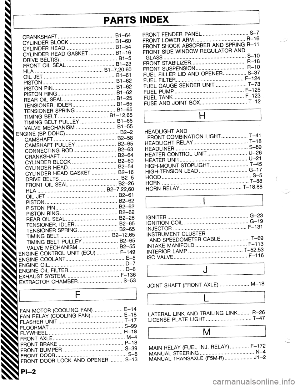
PARTS INDEX
I
CRANKSHAFT.. ....................................
I31 -64
CYLINDER BLOCK .............................. 61-60
CYLINDER HEAD..
............................... 81-54
CYLINDER HEAD GASKET .................
Bl-16
DRIVE BELT(S). ...................................... 81-5
FRONT OIL SEAL ................................ 81-23
HLA .............................................. Bl-7,20,60
OIL JET ................................................ 81-61
PISTON.. ...............................................
Bl-62
PISTON PIN..
........................................ 81-62
PISTON RING
....................................... 81-62
REAR
OIL SEAL..
................................. 81-25
TENSIONER, IDLER ............................. Bl-65
TENSIONER
SPRING ...........................
Bl-65
TIMING BELT ..................................
Bl-12,65
TIMING BELT PULLEY ........................
Bl-65
VALVE MECHANISM ........................... Bl-55
ENGINE
(BP DOHC) .................................... B2-2
CAMSHAFT ..........................................
82-58
CAMSHAFT PULLEY ...........................
B2-65
CONNECTING ROD..
........................... 82-63
CRANKSHAFT ......................................
B2-64
CYLINDER BLOCK ..............................
82-60
CYLINDER
HEAD.. ............................... B2-54
CYLINDER HEAD GASKET .................
82-16
DRIVE
BELTS.. .......................................
B2-5
FRONT
OIL SEAL ................................
82-26
H LA ..............................................
OIL JET .......................... B2-7iyL;;
......................
PISTON .................................................
B2-62
PISTON PIN ..........................................
82-62
PISTON RING..
..................................... 82-62
REAR OIL SEAL ................................... B2-28
TENSIONER, IDLER ............................. B2-65
TENSIONER SPRING ........................... B2-65
TIMING
BELT.. ................................
B2-12,65
TIMING BELT PULLEY ........................ 82-65
VALVE MECHANISM ........................... 82-55
ENGINE CONTROL UNIT (ECU) ............... F-149
ENGINE COOLANT
........................................ E-5
ENGINE OIL.. .................................................
D-7
ENGINE OIL FILTER.. .................................... D-8
’ EXHAUST SYSTEM. ...................................
F-136
EXTRACTOR CHAMBER .............................. S-53
F
FAN MOTOR (COOLING FAN). ................... E-14
FAN RELAY (COOLING FAN). ..................... E-18
FLASHER UNIT ............................................
T-17
FLOORMAT ..................................................
S-99
FLYWHEEL ..................................................
H-18
FRONT AXLE .................................................
M-4
FRONT BRAKE ............................................
P-l 8
FRONT BUMPER ......................................... S-39
FRONT DOOR ................................................
S-8
FRONT DOOR LOCK AND OPENER ..........
S-13
PI-2
FRONT FENDER PANEL ............................... S-7
FRONT LOWER ARM .................................. R-16
FRONT SHOCK ABSORBER AND SPRING R-11
FRONT SIDE WINDOW REGULATOR AND
GLASS ........................................................ S-10
FRONT STABILIZER..
................................... R-l 8
FRONT SUSPENSION .................................. R-l 0
FUEL FILLER LID AND OPENER..
.............. S-37
FUEL FILTER .............................................. F-l 24
FUEL GAUGE SENDER UNIT ..................... T-73
FUEL PUMP ............................................... F-125
FUEL TANK
................................................ F-123
FUSE AND JOINT BOX.. .............................. T-12
H
HEADLIGHT AND
FRONT COMBINATION LIGHT..
................ T-41
HEADLIGHT RELAY ..................................... T-l 8
HEADLINER ................................................. S-89
HEATER CONTROL UNIT.. ......................... U-26
HEATER UNIT
.............................................. U-21
HIGH-MOUNT STOPLIGHT
.......................... T-45
HIGH-TENSION LEAD ................................. G-l 7
HOOD ............................................................. S-5
HORN T-88
...........................................................
HORN RELAY
.......................................... T-18,88
.__. ’
I I
IGNITER .......................................................
G-23
IGNITION COIL.. .......................................... G-19
INJECTOR .................................................. F-l 31
INSTRUMENT CLUSTER
AND SPEEDOMETER CABLE
.................... T-69
INTAKE MANIFOLD ................................... F-113
INTERIOR LAMP ..................................... T-52,53
ISC VALVE.. ................................................ F-l 16
J
JOINT SHAFT (FRONT AXLE) .................... M-18
L
LATERAL LINK AND TRAILING LINK.. ....... R-26
LICENSE PLATE LIGHT.. ............................. T-47
i
M
I
---
MAIN RELAY (FUEL INJ. RELAY). ............ F-172
MANUAL STEERING ..................................... N-4
MANUAL TRANSAXLE (F5M-R). .................. Jl-2
Page 1067 of 1164

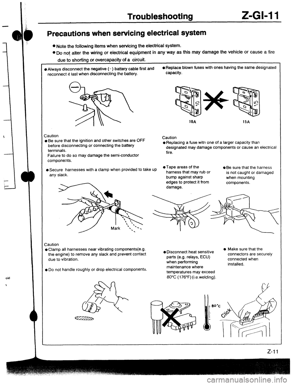
Troubleshootina Z-GM 1
Precautions when servicing electrical system
l Note the following items when servicing the electrical system.
l Do not alter the wiring or electrical equipment in any way as this may damage the vehicle or cause a fire
due to shorting or overcapacity of a circuit.
l Always disconnect the negative (- ) battery cable first and 0 Replace blown fuses with ones having the same designated
reconnect It last when disconnecting the battery. capacity.
1OA
15A
Zaution
l Be sure that the ignition and other switches are OFF
before disconnecting or connecting the battery
terminals.
Failure to do so may damage the semi-conductor
components. Caution l Replacing a fuse with one of a larger capacity than
designated may damage components or cause an electrical
fire.
l Secure harnesses with a clamp when provided to take Up l Tape areas of the
a Be sure that the harness
any slack. harness that may rub or
is not caught or damaged
bump against sharp
when mounting
edges to protect it from
components.
damage.
Caution
l Clamp all harnesses near vibrating components(e.g.
the engine) to remove any slack and prevent Contact
due to vibration.
l Do not handle roughly or drop electrical components.
l Disconnect heat sensitive
parts (e.g. relays, ECU)
when performing
maintenance where
temperatures may exceed l Make sure that the
connectors are securely
connected when
installed.
80°C (176°F) (i.e.welding).
oid
Page 1068 of 1164

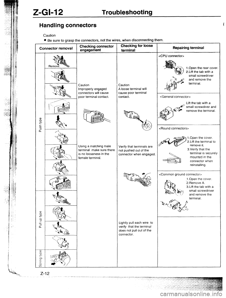
Z-GI-12 Troubleshooting
Handling connectors
Caution
l Be sure to grasp the connectors, not the wires, when disconnecting them.
1 .Open the rear cover.
2.Lift the tab with a
small screwdriver
and remove the
improperly engaged
connectors will cause
poor terminal contact. A loose terminal will
cause poor terminal
Lift the tab with a
remove the terminal.
1 .Open the cover.
2.Lift the terminal to
Using a matching male
is no looseness in the
female terminal. Verify that terminals are
connector when engaged. 3.Verify that the
terminal IS securely
mounted in the
connector when
3.Lift the tab with a
small screwdriver
and remove the
Lightly pull each wire to
verify that the terminal
does not pull out of the