Page 975 of 1164
TROUBLESHOOTING GUIDE U
Case 6 Expansion valve stuck open
Measured pressure
Low-pressure: Above 245 kPa (2.5 kg/cm2, 35.6 psi)
High-pressure: 1,864-l ,962 kPa (19-20 kg/cm2, 270-284 psi)
Condition
Insufficient cooling
QMUOUX-093
23UOUX-01’
1. Check whether there is frost or heavy dew on the suction
pipe (between cooling unit and compressor).
2. If neither is found, refer to “Excessive refrigerant or insuffi-
cient condenser cooling”; page U-17.
3. If either is found, replace the expansion valve.
(Refer to page U-39.)
Case 7 Faulty compressor
Measured pressure
Low-pressure: 392-589 kPa (4-6 kg/cm2, 57-85 psi)
High-pressure: 687-981 kPa (7-10 kg/cm2, loo-142 psi)
Condition
No cooling
MOISTURE EVACUATE
IN SYSTEM SYSTEM
I
9MUOUX-095
1. Run the engine at a fast idle.
2. Verify that the magnetic clutch is ON when the A/C switch
and blower switch are ON.
3. If the magnetic clutch remains OFF, refer to “Magnetic
clutch does not operate”; page U-10.
u-19
Page 986 of 1164

U AIR CONDITIONER
AIR CONDITIONER
STRUCTURAL VIEW
/
23UOUX-02
6. Refrigerant pressure switch No.2
Inspection.. ................................. page U-55
7. Condenser fan
Removal / Installation.. ................ page U-57
Inspection.. ................................. page U-57
8. Cooling unit
Removal / Installation .................. page U-38
Disassembly / Assembly.. ........... page U-39
Replacement.. ............................ page U-39
On-vehicle inspection ................. page U-40
Inspection ................................... page U-40
9. A/C relay
Inspection ................................... page U-56 --’
10. Condenser fan relay
Inspection ................................... page U-56 1. Compressor
Removal / Installation . . . . . . . . . . . . . . . . . . page U-41
Disassembly / Assembly... . . . . . . . . . . page U-43
Adjustment . . . . . . . . . . . . . . . . . . . . . . . . . . . . . . . . . page U-50
2. Magnetic clutch
Disassembly / Assembly . . . . . . . . . . . . . page U-51
Inspection . . . . . . . . . . . . . . . . . . . . . . . . . . . . . . . . . . . page U-51
Adjustment . . . . . . . . . . . . . . . . . . . . . . . . . . . . . . . . . page U-51
3. Condenser
Removal / Installation . . . . . . . . . . . . . . . . . . page U-53
Inspection . . . . . . . . . . . . . . . . . . . . . . . . . . . . . . . . . . . page U-53
4. Receiver/Drier
Removal / installation . . . . . . . . . . . . . . . . . . page U-52
5. Refrigerant pressure switch No.1
Inspection . . . . . . . . . . . . . . . . . . . . . . . . . . . . . . . . . . . page U-55
u-30
Page 1003 of 1164
AIR CONDITIONER U
r 23UOUX-036
L 23UOUX.03
I
L
23UOUX-03 7
Shaft Seal Replacement
1. Remove the armature plate.
Note
l Removal of the clutch pulley and coil is not
necessary.
2. Remove the felt seal and snap ring.
3. Remove the shim(s).
4. Insert the
SST into the compressor aligning the cutout of
the
SST with the groove of the seal plate.
5. Rotate the
SST counterclockwise to make sure that the
cutout is engaged with the seal plate.
6. Pull out the seal plate.
7. Insert the
SST into the compressor aligning the cutout of
the
SST with the metal pawl of the shaft seal.
8. Rotate the
SST counterclockwise to make sure that the cut-
off is engaged with the metal pawl.
9. Pull out the shaft seal.
u-47
Page 1007 of 1164
AIR CONDITIONER
MAGNETIC CLUTCH
Disassembly / Assembly
1. Disassemble the magnetic clutch as shown in the figure.
2. Assemble the magnetic clutch in the reverse order of removal.
I
1. Pressure plate
2. Rotor pulley 3. Stator
4. Shim
Inspection
Stator
1. Verify continuity between the stator terminals.
Note
l Set the ohmmeter to x 1,000 range.
2. If there is no continuity, replace the stator.
Adjustment
Magnetic clutch clearance
Adjust the clearance between the pressure plate and the ro-
tor pulley by selecting and installing the proper shim(s).
Clearance: 0.4-0.5mm (0.016-0.020 in)
Part number Thickness mm (in)
8455 61 L15
0.2 (0.008)
8456 61 L15
0.5 (0.020)
u-51
Page 1011 of 1164

AIR CONDITIONER U
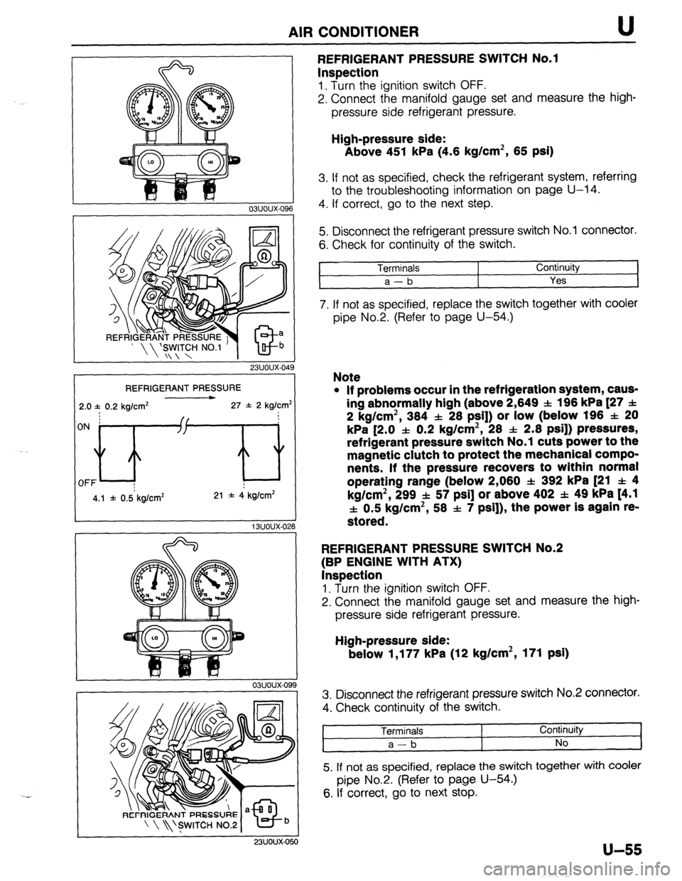
REFRIGERANT PRESSURE
2.0 f 0.2 kg/cm* 27 f 2 kg/cm’
4.1 f 0.5 kg/cm* 21 * 4 kg/cm*
03uoux-09
9
23UOUX-050
REFRIGERANT PRESSURE SWITCH No.1
Inspection
1. Turn the ignition switch OFF.
2. Connect the manifold gauge set and measure the high-
pressure side refrigerant pressure.
High-pressure side:
Above 451 kPa (4.6 kg/cm2, 65 psi)
3. If not as specified, check the refrigerant system, referring
to the troubleshooting information on page U-14.
4. If correct, go to the next step.
5. Disconnect the refrigerant pressure switch No.1 connector.
6. Check for continuity of the switch.
Terminals
1 Continuity
a-b
Yes I
7. If not as specified, replace the switch together with cooler
pipe No.2. (Refer to page U-54.)
Note
l If problems occur in the refrigeration system, caus-
ing abnormally high (above 2,649 SL: 196 kPa [27 f
2 kg/cm2, 384 f 28 PSI]) or low (below 196 f 20
kPa [2.0 f 0.2 kg/cm2, 28 & 2.8 psi]) pressures,
refrigerant pressure switch No.1 cuts power to the
magnetic clutch to protect the mechanical compo-
nents. If the pressure recovers to within normal
operating range (below 2,080 f 392 kPa [21 f 4
kg/cm2, 299 f 57 psi] or above 402 f. 49 kPa t4.1
f 0.5 kg/cm2, 58 f 7 psi]), the power is again re-
stored.
REFRIGERANT PRESSURE SWITCH No.2
(BP ENGINE WITH ATX)
Inspection
1. Turn the ignition switch OFF.
2. Connect the manifold gauge set and measure the high-
pressure side refrigerant pressure.
High-pressure side:
below 1,177 kPa (12 kg/cm2, 171 psi)
3. Disconnect the refrigerant pressure switch No.2 connector.
4. Check continuity of the switch.
Terminals
a-b I Continuity
No
5. If not as specified, replace the switch together with cooler
pipe No.2. (Refer to page U-54.)
6. If correct, go to next stop.
u-55
Page 1015 of 1164

TD
TECHNICAL DATA
MEASUREMENTS .................................... TD- 2
ENGINE (B6 AND BP SOHC)
ENGINE (BP DOHC) ... .................................................. ;;- f
LUBRICATION SYSTEM ........................... TDI 6
COOLING SYSTEM .................................. TD- 6
FUEL AND EMISSION CONTROL
SYSTEMS ............................................. TD- 9
ENGINE ELECTRICAL SYSTEM ................ TD-10
CLUTCH ................................................. TD-11
MANUAL TRANSAXLE (F5M-R) ................ TD-12
MANUAL TRANSAXLE (GSM-R) ................ TD-13
AUTOMATIC TRANSAXLE ....................... TD-14
FRONT AND REAR AXLES.. .....................
STEERING SYSTEM ................................ ;;-;;
-
BRAKING SYSTEM .................................. TD-16
WHEELS AND TIRES ............................... TD-19
SUSPENSION ......................................... TD-19
BODY ELECTRICAL SYSTEM ................... TD-20
HEATER AND AIR CONDITIONER
SYSTEMS ............................................. TD-21
STANDARD BOLT AND NUT TIGHTENING
TORQUE .............................................. TD-21
23UTDX-001
Page 1025 of 1164
TECHNICAL DATA
H. CLUTCH
1 Full stroke Englne/lransaxle
86 SOW
I BP SOHC
I BP DOW
Item 1 05M-R FSM-R
Clutch control Hydraulic Clutch pedal
Type
Suspended
Pedal ratio 6.55
mm (in) I 135 (5.3 2)
Height (With carpet) mm (in) 1 1E t6-204 (7.72-8.03)
Free olav
L .-- 7 --a mm (in) I
t I , 5.0-l 3.0 (0.197-0.512)
Distance to carpet when clutch fully
disengaged mm (in) Minimum 41.0 (1.61) Flywheel
Runout limit mm (in) I 0.2 (0.008) Clutch disc
, Type
Single dry plate
Runout limit mm (in) 1 LO.027)
Wear limit mm (in) I 0.3 1 (0.012) from rivet head
Outer diameter mm (in)
1s , I )O (7.48) 200 (7.87)
I 215 (8.46)
Inner diameter mm (in) 130 (5 150 (5.91)
-.
Facing thcknes! 3 mm (in) Flywheel side [O. 138)
Pressure elate side 3.5 10.1:
, 38) 3.8 (0.150)
1 3.8 (0.150) Clutch cover
Type
Diaphragm spring
Set load N (kg, lb) [ 3,630 (370, 814) 1 3,826 (390, 858) 1 3,846 (392. 862)
TD-11
Page 1026 of 1164

TD TECHNICAL DATA
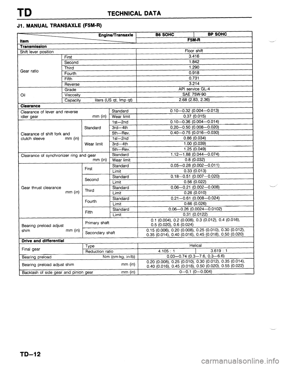
Jl l MANUAL TRANSAXLE (FSM-R)
BB SOHC
l- BP SOHC I
F %M.R
I
1
Floor shift Item
Transmission Shift lever oosition Engine/lransaxle
First
Second
-I?-:-.4
I 0.918
I
n ‘31
I Gear ratio lllll”
Fourth
Fifth
Reverse
Grade
Oil Viscosity
Capacity liters (US qt, Imp qt) Clearance
Clearance of lever and reverse Standard
idler gear
mm (in) Wear limit
1 st-2nd
Standard 3rd-4th
Clearance of shift fork and Sth-Rev.
clutch sleeve mm (in)
1 st-2nd
Wear limit 3rd-4th
I 5th~Rev. j
Clearance of synchronizer ring and gear Standard ) mm (in)
Wear limit 3.416
1.842
1.290
ce GL-4
SW-90
I
V.I.
3.214
API servil
SAE 7t
2.68 (2.83, 2.36)
0.1 O-O.32 (0.004-o.
0.37 (0.015)
0.1 O-O.36 (0.004-o.
0.20-0.50 (0.008-O.
0.40-0.75 (0.016-O.
0.86 (0.034)
1 .oo (0.039)
i 3c /n n/la
I .L” \“.“T”,
1.12-l .88 (0,044-O.
0.8 (0.032)
0.05-0.28 (0.002-0.011)
0.33 (0.013)
0.18-0.51 (0.007-0.020)
0.56 (0.022)
0.06-0.21 (0.002-0.008)
0.26 (0.010)
0.21-0.61 (0.008-0.024)
0.66 (0.026)
0.06-0.26 (0.0024-0.0102)
0.31 (0.0122)
(0.008), 0.3 (0.012), 0.4 (0.016) Fifth Standard
Limit
0.1 (0.004) 0.2
Rnnrinn nrdnari adjust Primary shaft
0.5 (0.020) 0.6
I shim mm (in)
Secondary shaft 0.15 (0.006) 0.20 (0.008) 0.25 (0.
~-~?r;liln
I Final gear
Bearing preload
I Bearing preload adjust shim
[Backlash of side gear and pinion gear
I
I
030)
,074)
I
First Standard
Limit
Second Standard
Limit
Gear thrust clearance
mm (in) Third Standard
Limit
Fourth Standard
Limit
(0.024j
OlO), 0.30 (0.012)
I
I V.“” \“‘V I .,, “.~lV \Y... VW,? “I ,-
\... 018j, 0.50 (0.020)
Helical
4.105 : 1
I 3.619 : 1
N,m (cm-kg, in-lb) 0.03-0.74 (0.3-7.6, 0.3-6.6)
n qn
mm (in)
“.L” ,“.“U mnr78), 0.25 (o.oio), 0.30 (0.012) 0.35
(0.014)
0.40 (0.01 6) 0.45 (0.018),
0.50 (0.020) 0.55 (0.022)
-~ -1
mm (in) j o-o.1 (O-0.004 --
--’
TD-12