Page 733 of 1164

REAR SUSPENSION (STRUT) R
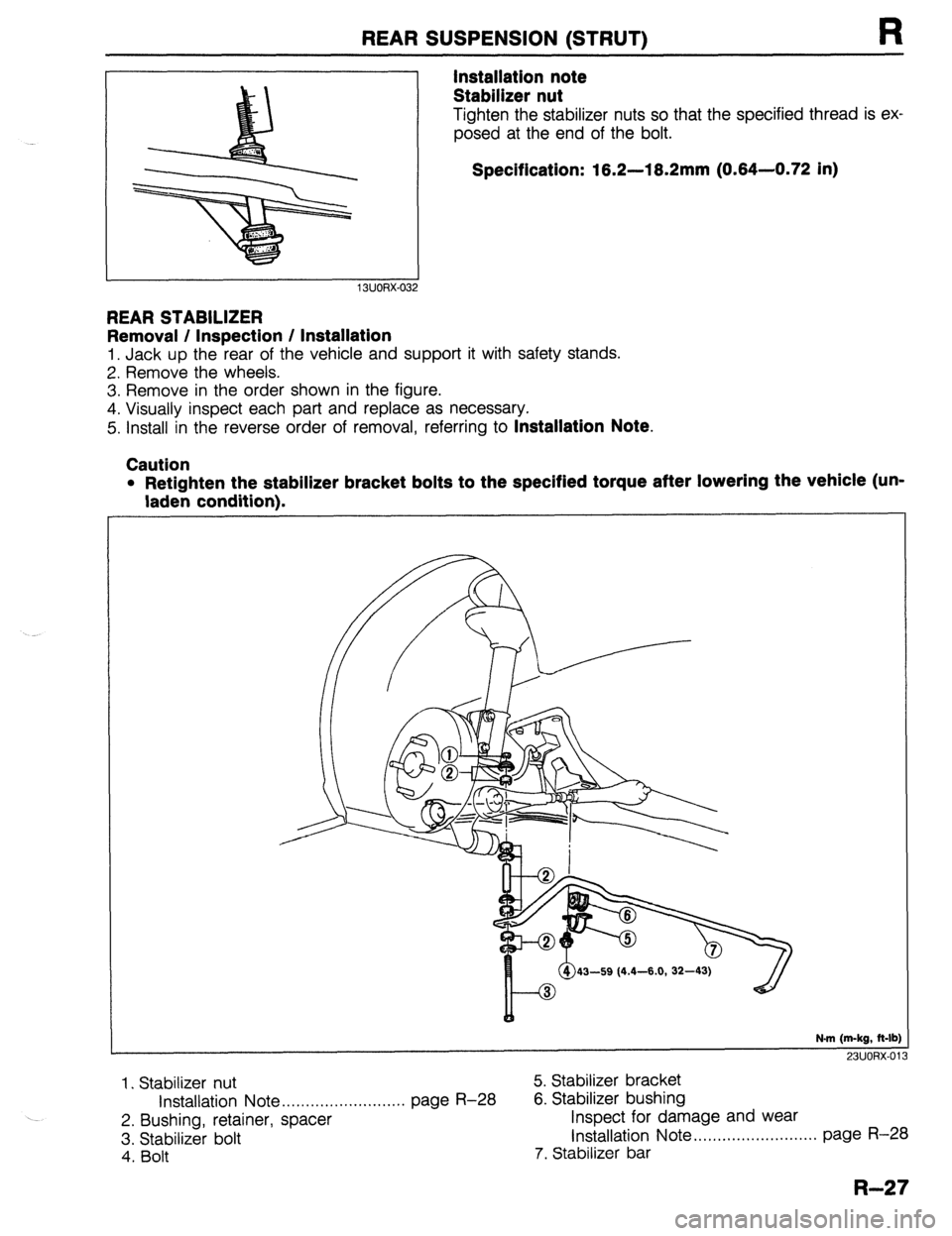
Installation note
Stabilizer nut
Tighten the stabilizer nuts so that the specified thread is ex,
posed at the end of the bolt.
Specification: 16.2-18.2mm (0.84-0.72 in)
REAR STABILIZER
Removal / Inspection / Installation
1. Jack up the rear of the vehicle and support it with safety stands.
2. Remove the wheels.
3. Remove in the order shown in the figure.
4. Visually inspect each part and replace as necessary.
5. Install in the reverse order of removal, referring to
Installation Note.
Caution
l Retighten the stabilizer bracket bolts to the specified torque after lowering the vehicle (un-
laden condition).
43-59 (4.4-6.0, 32-4
N-m (m-kg, ft-lb)
731KmX.01
---_
1. Stabilizer nut 5. Stabilizer bracket
Installation Note . . . . . . . . . . . . . . . . . . . . . . . . . . page R-28 6. Stabilizer bushing
2. Bushing, retainer, spacer Inspect for damage and wear
3. Stabilizer bolt Installation Note .,,,,,.................... page R-28
4. Bolt 7. Stabilizer bar
R-27
Page 735 of 1164

REAR CROSSMEMBER
Removal / Installation
REAR SUSPENSION (STRUT) R
1. Jack up the vehicle and support it with safety stands.
2. Remove the wheels and tires.
3. Remove the brake pipe holder.
4. Remove in the order shown in the figure.
5. Inspect all parts and repair or replace as necessary.
6. Install in the reverse order of removal, referring to
Installation Note.
7. After installation, check the rear wheel alignment and adjust it if necessary.
Caution
l Loosely tighten the lateral link and trailing link bolts and nuts when installing. Lower the vehi-
cle and tighten all nuts and bolts to the specified torques with the vehicle unladen.
46-63 (4.7-6.4, 34-46)
66-117 (6.7-11.9, 63-66)
I
66-95 (W-9.7,
43-59 (4.4-6.0, 32-43)
63-93 (6.4-9.5, 46-69)
N.m (m-kg, ft-lb)
‘)‘)I ano” n,
1. Nut (Stabilizer)
Installation Note . . . . . . . . . . . . . . . . . . . . . . . . . .
2. Bushing and retainer
3. Bolt, retainer and bushing
4. Retainer, bushing and spacer
5. Bolt (Lateral link)
6. Bolt (Trailing link)
7. Bolt (Trailing link) 8. Trailing link
page R-28 9. Bolt (Lateral link)
10. Lateral link (front and rear)
Il. Bolt
12. Rear stabilizer
13. Bolt and washer
14. Rear crossmember
R-29
Page 876 of 1164
T SWITCHES
03UOTX-026
H&N CAP
03UOTX-02 8
03UOTX-02s
SWITCH
Removal / Installation
Ignition switch
1. Remove the negative battery cable.
2. Remove the steering column cover.
3. Remove the screw and the ignition switch.
4. Install in the reverse order of removal.
Hazard warning switch
1. Remove the meter hood.
2. Remove the screws and the hazard switch.
3. Install in the reverse order of removal.
Cruise control switch
(set/coast and resume/accel switch)
1. Remove the steering wheel cap.
2. Remove the cruise control switch as shown in the figure.
3. Install in the reverse order of removal.
Inspection
1. Check for continuity between the terminals with an
ohmmeter.
Remote control door mirror switch
CLASS DIRECTION a b c d i k I
UP o---o
0 0
1 UP
I I lo! I-l7ol
o----O: Indicates continuity
T-20
Page 879 of 1164
SWITCHES T
COMBINATION SWITCH
Removal / Installation (Except Canada without cruise control system)
1. Remove in the order shown in the figure.
2. Install in the reverse order of removal.
1. Horn cap
2. Steering wheel
3. Steering column cover 4. Combination switch
Disassembly I Assembly , . , . . . . . . . . . . page T-24
Inspection .,......,.,....,.*..*..,.,......... page T-27
T-23
Page 881 of 1164
SWITCHES T
Removal / Installation (Canada without cruise control system)
1. Remove in the order shown in the figure.
2. Install in the reverse order of removal.
1. Horn cap
2. Steering wheel
3. Steering column cover 4. Combination switch
13UOTX-01;
Disassembly / Assembly . . . . . . . . . . . . . page T-26
Inspection . . , . . . . . . . . . . . . . . . . . . . . . . . . . . . ,. . , . page T-28
T-25
Page 1015 of 1164

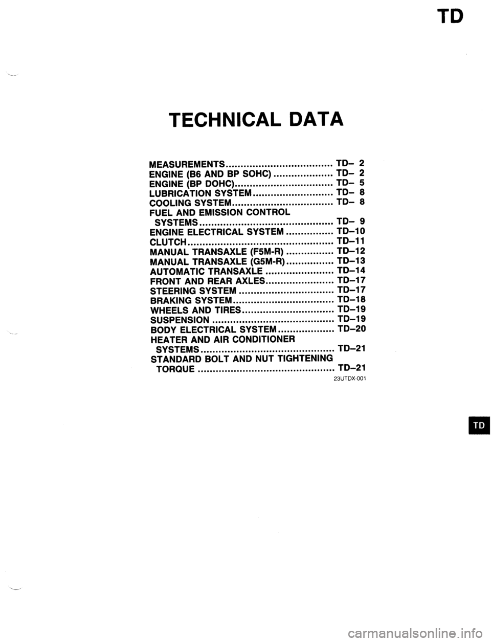
TD
TECHNICAL DATA
MEASUREMENTS .................................... TD- 2
ENGINE (B6 AND BP SOHC)
ENGINE (BP DOHC) ... .................................................. ;;- f
LUBRICATION SYSTEM ........................... TDI 6
COOLING SYSTEM .................................. TD- 6
FUEL AND EMISSION CONTROL
SYSTEMS ............................................. TD- 9
ENGINE ELECTRICAL SYSTEM ................ TD-10
CLUTCH ................................................. TD-11
MANUAL TRANSAXLE (F5M-R) ................ TD-12
MANUAL TRANSAXLE (GSM-R) ................ TD-13
AUTOMATIC TRANSAXLE ....................... TD-14
FRONT AND REAR AXLES.. .....................
STEERING SYSTEM ................................ ;;-;;
-
BRAKING SYSTEM .................................. TD-16
WHEELS AND TIRES ............................... TD-19
SUSPENSION ......................................... TD-19
BODY ELECTRICAL SYSTEM ................... TD-20
HEATER AND AIR CONDITIONER
SYSTEMS ............................................. TD-21
STANDARD BOLT AND NUT TIGHTENING
TORQUE .............................................. TD-21
23UTDX-001
Page 1016 of 1164

TD TECHNICAL DATA
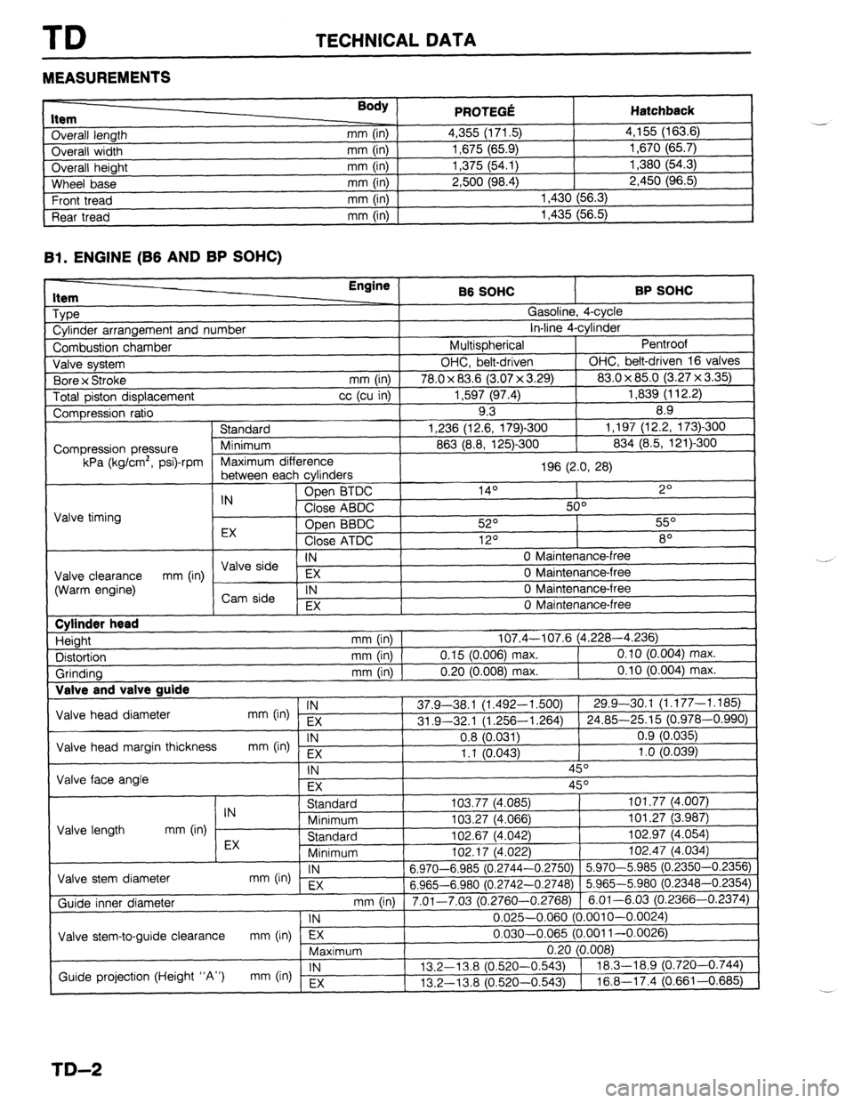
MEASUREMENTS
I ._.____2_ nem
Overall length
Overall width
Overall height
Wheel base
Front tread
Rear tread Body ) mm (in)
mm (in)
mm (in)
mm (in)
mm (in)
mm (in) PRfWFr.f! . . ..s .-VW Hatchback 4,355 (171.5) 4,155 (163.6)
1,675 (65.9) 1,670 (65.7)
1,375 (54.1) 1,380 (54.3)
2,500 (98.4) 2,450 (96.5)
1,430 (56.3)
1,435 (56.5)
Bl. ENGINE (B6 AND BP SOHC)
1 Type
1 Cylinder arrangement and number Engine
86 SOHC BP SOHC
^ . . _
,?
I
uasollne, 4-cyw
. . *. 4
in-line 4-cyrinaer
Pentroof
1
I Combustion chamber I Multispherical
J Valve system OHC, belt-driven OHC, belt-driven 16 valves
. , I (3.07 x 3.29) 83.0 x 85.0 (3.27 x 3.35)
Total piston displacement cc (cu in) 1,597 (97.4) 1,839 (112.2)
Compression ratio 9.3 8.9
) Standard 1,236 (12.6, 179)-300 1,197 (12.2, 173)300
I
863 (8.8, 125)-300 834 (8.5, 121)300 1 Bore x Stroke
mm (in) I 78.0 x 83.6
Compression pressure
kPa (kg/cm’, psi)-rpm
E cvlinders 1 Maximum difference
196 (2.0, 28)
I
, ------- ---- -J - IN Open BTDC 14O 2O
Close ABDC 50°
Valve timing
Open BBDC 52O 55O
EX
Close ATDC 12O 8O
IN 0 Maintenance-free I \/AIo &-in --
Valve clearance EX 0 Maintenance-free
(Warm engine) mm (in) / ,,syi: 1
IN 0 Maintenance-free
I , EX 0 Maintenance-free
I Cylinder head
Height
Distortion
Grinding Valve and T _
Valve head diameter
Valve head margin thickness
Valve face angle IN mm (in) EX
IN
mm b-4 Fx mm (in) 107.4-107.6 (4.228-4.236)
mm (in) 0.15 (0.006) max. 0.10 (0.004) max.
mm (in) 0.20 (0.008) max. 0.10 (0.004) max.
37.9-38.1 (1.492-l ,500) 29.9-30.1 (1.177-1.185)
31 .Q-32.1 (1.256-l ,264) 24.85-25.15 (0.978-0.990)
0.8 (0.031) 0.9 (0.035)
1.1 10.043) 1 .o (0.039)
-, ,
\- I
IN 45O
EX 45O
I I Standard
IN
Minimum
Valve length mm (in)
EX Standard
Minimum I”L. I, \*.“cL
Valve stem diameter IN
mm On) EX 6.970-6.985 (0.2744-
6.965-6.980 (0.2742-
Guide inner diameter
I Valve stem-to-guide clearance mm (in) lTj7---- ,
Maximum 103.77 (4,085) 101.77 (4.007)
103.27 (4.066) 101.27 (3.987)
102.67 (4.042) 102.97 (4.054)
,n+ 47 IA noo
1 102.47 (4.034)
-0.2750) 5.970-5.985 (0.2350-0.2356)
-0.2748) 5.965-5.980 (0.2348-0.2354)
3.2760-0.2768) 6.01-6.03 (0.2366-0.2374)
0.025-0.060 (0.001 O-0.0024)
0.030-0.065 (0.001 l-0.0026)
-.
I
mm (in) 1 7.01-7.03 (r ‘
1 IN
Guide projection (Height “A”) IN
mm (in) Ex 13.2-l 3.8 (0.520-
13.2-13.8 (0.520-
TD-2
Page 1025 of 1164
TECHNICAL DATA
H. CLUTCH
1 Full stroke Englne/lransaxle
86 SOW
I BP SOHC
I BP DOW
Item 1 05M-R FSM-R
Clutch control Hydraulic Clutch pedal
Type
Suspended
Pedal ratio 6.55
mm (in) I 135 (5.3 2)
Height (With carpet) mm (in) 1 1E t6-204 (7.72-8.03)
Free olav
L .-- 7 --a mm (in) I
t I , 5.0-l 3.0 (0.197-0.512)
Distance to carpet when clutch fully
disengaged mm (in) Minimum 41.0 (1.61) Flywheel
Runout limit mm (in) I 0.2 (0.008) Clutch disc
, Type
Single dry plate
Runout limit mm (in) 1 LO.027)
Wear limit mm (in) I 0.3 1 (0.012) from rivet head
Outer diameter mm (in)
1s , I )O (7.48) 200 (7.87)
I 215 (8.46)
Inner diameter mm (in) 130 (5 150 (5.91)
-.
Facing thcknes! 3 mm (in) Flywheel side [O. 138)
Pressure elate side 3.5 10.1:
, 38) 3.8 (0.150)
1 3.8 (0.150) Clutch cover
Type
Diaphragm spring
Set load N (kg, lb) [ 3,630 (370, 814) 1 3,826 (390, 858) 1 3,846 (392. 862)
TD-11