Page 17 of 20
.
54Tighten the manifold securing nuts
progressive")
Refitting
52Refitting is a reversal of removal, bearing
in mind the following points.
53Ensure that all mating faces are clean and
renew the gasket(s).
54Tighten the manifold securing nuts
progressively to the specified torque.
55Make sure that all hoses, pipes and wires
are correctly reconnected, and if the fuel
supply hose was originally secured with a
crimped type clip, discard this and use a new
worm drive clip on refitting.
56On completion, refill the cooling system,
adjust the throttle cable and check and if
necessary adjust the idle speed and mixture.
Removal
1Disconnect the battery negative lead.
2Remove the air cleaner and pull the hot air
pick-up pipe from the exhaust manifold hot air
shroud.
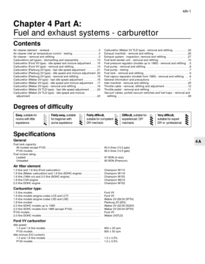
3Remove the securing screws (1 screw on
DOHC models, 2 screws on SOHC models, 3
screws on CVH models) and lift the hot air
shroud from the manifold. Note the position of
the coolant hose bracket which is secured by
the front hot air shroud securing screw on
SOHC models (see illustration).
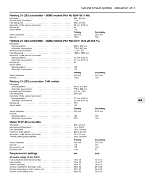
4Unscrew the securing nuts, and disconnect
the exhaust downpipe from the manifold (see
illustration). Recover the gasket. Support the
exhaust downpipe from underneath thevehicle, with an axle stand for example, to
avoid placing unnecessary strain on the
exhaust system.
5Disconnect the HT leads from the spark
plugs, if necessary identifying them for
locations, and place them to one side out of
the way.
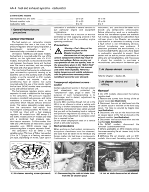
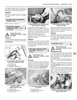
6Unscrew the eight securing nuts, noting the
location of the front engine lifting bracket
secured by the front two nuts on SOHC
models, and lift the manifold from the cylinder
head. Recover the gasket(s) where applicable
(see illustrations).
Refitting
7Refitting is a reversal of removal, bearing in
mind the following.
8Ensure that all mating faces are clean, and
renew all gaskets. Note that on CVH models,
no gasket is fitted between the manifold andcylinder head in production, but a gasket
must be used when refitting. Where
applicable, remove the plastic spacer from the
rear manifold stud before fitting the gasket
(see illustrations).
26Exhaust manifold - removal
and refitting
Fuel and exhaust systems - carburettor 4A•17
4A
26.6a Unscrew the exhaust manifold
securing nuts . . .
26.8c Fitting the exhaust manifold -
DOHC models26.8b Remove the plastic spacer (arrowed)
before fitting exhaust manifold gasket -
CVH models26.8a Exhaust manifold gaskets in position
on cylinder head - DOHC models
26.6d SOHC models have separate
manifold gaskets for each exhaust port26.6c . . . and lift off the exhaust manifold -
SOHC models26.6b . . . noting the location of the front
engine bracket . . .
26.4 Unscrewing an exhaust downpipe
securing nut26.3 Exhaust manifold hot air shroud
showing securing screws (1 and 3) and
coolant hose clip (2) - SOHC models
Page 18 of 20

9Tighten the manifold securing nuts
progressively to the specified torque, and
similarly tighten the exhaust downpipe
securing nuts. Do not forget to fit the engine
lifting bracket on SOHC models.
10Ensure that the HT leads are reconnected
to their correct cylinders.
Inspection
1The exhaust system should be examined for
leaks, damage, and security at regular
intervals. To do this, apply the handbrake, then
start the engine and allow it to idle. Lie down on
each side of the vehicle in turn and check the
full length of the exhaust system for leaks,
while an assistant temporarily places a wad of
cloth over the tailpipe. If a leak is evident, stop
the engine and use a proprietary repair kit to
seal it. If an excessive leak or damage is
evident, renew the relevant section of the
exhaust system. Check the rubber mountings
for deterioration and renew if necessary.
Removal
2To remove the exhaust system, jack up the
front and rear of the vehicle and support on
axle stands (see “Jacking and Vehicle
Support”).
3If desired, the exhaust downpipe can be
removed independently of the remainder of
the system, and similarly the main part of the
system can be removed, leaving the
downpipe in place.
4To remove the downpipe, unscrew the
securing nuts and disconnect the downpipe
from the manifold. Recover the gasket.
Unscrew the two nuts and bolts, and separate
the downpipe flanged joint from the remainder
of the system. Withdraw the downpipe (see
illustrations).
5To remove the main section of the exhaust
system leaving the downpipe in place,
unscrew the two securing nuts and bolts and
separate the flanged joint from the downpipe.
Unhook the rubber mountings and withdraw
the system from underneath the vehicle. The
number and type of rubber mountings variesaccording to model (see illustrations). If
necessary to avoid confusion, note how the
mountings are fitted to enable correct
refitting. Note that on P100 models the
system must be manipulated to pass over the
rear axle.
Refitting
6Refitting is a reversal of removal, but ensure
that all mating faces are clean, and fit a new
gasket between the downpipe and manifold
(see illustration). Do not fully tighten the joint
27Exhaust system - inspection,
removal and refitting
4A•18Fuel and exhaust systems - carburettor
27.4a Exhaust downpipe-to-manifold
flanged joint viewed from underneath
vehicle27.5a Rear exhaust section mounting -
Hatchback model
27.9a Cutting point when fitting a service replacement exhaust system section - Saloon,
Hatchback and Estate models
X = 1639 mm for all models up to 1987 except 1.3 and 1.6 litre Hatchback
X = 1681 mm for 1.3 and 1.6 litre Hatchback models up to 1987
X = 2063 mm for all models from 1987
27.6 Fit a new downpipe-to-manifold
gasket27.5b Rear exhaust mounting - P100 model
27.4b Exhaust downpipe-to-main system
flanged joint
Page 19 of 20
 to the
underbody.
7Service")
fittings until the system is in position and
correctly aligned in its mountings under the
vehicle. Ensure that no part of the exhaust
system is closer than 25.0 mm (1.0 in) to the
underbody.
7Service replacement exhaust systems are
available in three sections; downpipe, centre
section and rear section. The service replace-
ment sections fit together using socket joints,
therefore the centre section of a production
exhaust system cannot be renewed without
also renewing the rear section.
8To renew the centre and/or rear section(s)
of the exhaust system, first remove the main
system as described in paragraph 5.9To fit a service replacement rear section to
a production system, use a hacksaw to cut
through the pipe at the applicable point
shown (see illustrations). Apply exhaust
sealant to the mating surfaces of the two
sections, then push the two sections together
and fit a U-bolt clamp to the centre of the
joint. Do not fully tighten the U-bolt clamp
nuts until the system is in position and
correctly aligned in its mountings under the
vehicle.
10To renew a service replacement section,
unscrew the nuts and remove the U-bolt
clamp from the joint. Tap around the joint to
break the seal, and separate the centre andrear sections. Ensure that the joint mating
surfaces are clean, then apply exhaust
sealant, push the new section onto the
remaining section, and fit the U-bolt clamp to
the centre of the joint. Do not fully tighten the
U-bolt clamp nuts until the system is in
position and correctly aligned in its mountings
under the vehicle.
Refer to Chapter 5, Section 22 (see
illustration).
28Vacuum valves, ported vacuum
switches and fuel traps -
removal and refitting
Fuel and exhaust systems - carburettor 4A•19
4A
28.1 Low vacuum enrichment ported vacuum switch location in
inlet manifold - model with Weber 2V carburettor27.9b Cutting point when fitting a service replacement exhaust
system section - P100 models
X = 226 mm
Page 20 of 20
Page:
< prev 1-8 9-16 17-24