1992 BMW 325i contact
[x] Cancel search: contactPage 220 of 759

210-
6
CLUTCH
9
.
Clean
and
inspectrelease
bearing
guide
sleeve
on
transmission
.
Install
release
lever
and
release
bearing
.
See
Fig
.
11
.
A
0011582
Fig
.
11
.
Clutchrelease
bearing
correctly
installed
on
guide
sleeve
(A)
.
Bearing
tabs
(B)
align
with
contact
points
(C)
on
release
lever
.
10
.
Insta¡¡
transmission
.
See230
Manual
Transmission
.
Tightening
Torques
"
Flywheel
to
crankshaft
(use
new
bolts)
M42/M44
engines
....
.
..
...
....
120
Nm
(89
ft-Ib)
All
others
..........
..
.
..
......
105
Nm
(77
ft-Ib)
"
Pressure
píate
to
flywheel
M8
8
.8
grade
......
...
.
.
........
24
Nm
(18
ft-Ib)
M8
10
.9
grade
.....
..
..
..
.......
34
Nm
(25
ft-Ib)
CLUTCH
MECHANICAL
Transmission
pilot
bearing,
replacing
1
.
Remove
clutch
as
described
earlier
.
2
.
Remove
transmission
pilot
bearing
from
end
ofcrank-
shaft
using
BMW
special
tool
no
.
11
2
340,
or
equiva-
lent
.
3
.
Press
new
bearing
finto
placeusing
BMW
Specíal
Tool
no
.
11
2
350,or
equivalent
.
Page 238 of 759

250-
4
GEARSHIFT
LINKAGE
r%
;
5
(((((C
"
~
;
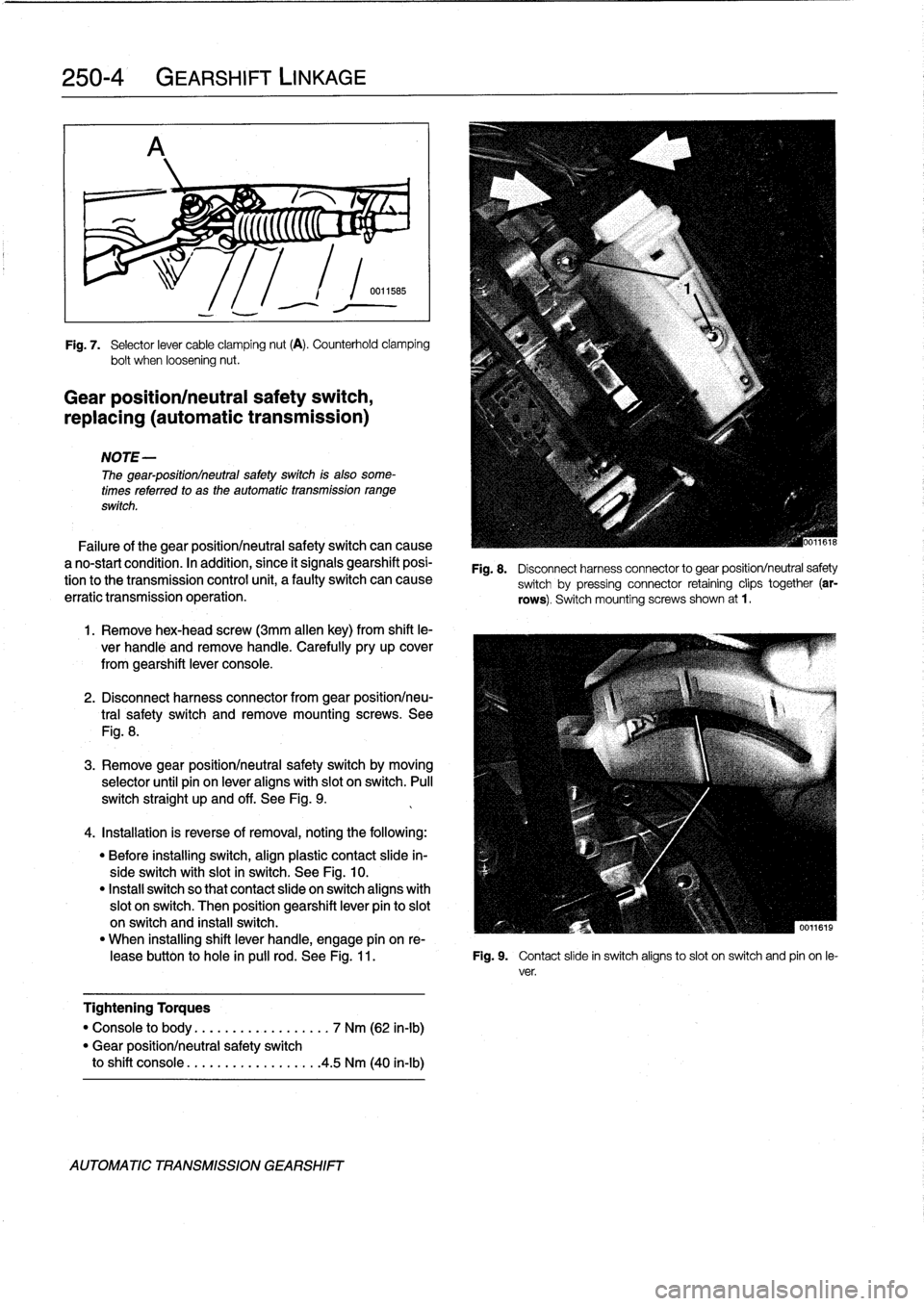
Fig
.
7
.
Selector
lever
cable
clamping
nut
(A)
.
Counterhold
clamping
bolt
when
loosening
nut
.
Gear
position/neutral
safety
switch,
replacing
(automatic
transmission)
NOTE-
The
gear-positionlneutral
safetyswitch
is
also
some-
times
referred
to
as
the
automatic
transmission
range
switch
.
Failure
of
the
gear
positionlneutral
safetyswitch
can
cause
a
no-start
condition
.
In
acidition,
since
it
signals
gearshift
posi-
tion
tothe
transmission
control
unit,
a
faulty
switch
can
cause
erratic
transmission
operation
.
1
.
Remove
hex-head
screw
(3mm
allen
key)
from
shift
le-
ver
handle
and
remove
handle
.
Carefully
pry
up
cover
from
gearshift
lever
console
.
2
.
Disconnect
harness
connector
from
gear
positionlneu-
tral
safety
switch
andremove
mounting
screws
.
See
Fig
.
8
.
3
.
Remove
gear
positionlneutral
safety
switch
by
moving
selector
until
pin
on
lever
aligns
with
slot
on
switch
.
Pull
switch
straight
up
and
off
.
See
Fig
.
9
.
4
.
Installation
is
reverse
of
removal,
noting
the
following
:
"
Before
installing
switch,
align
plastic
contact
slide
in-
sideswitch
with
slot
in
switch
.
See
Fig
.
10
.
"
Instan
switch
so
that
contact
slide
on
switch
aligns
with
slot
on
switch
.
Then
position
gearshift
lever
pin
to
slot
on
switch
and
install
switch
.
"
When
installing
shift
lever
handle,
engage
pín
on
re
leasebutton
to
hole
in
pulí
rod
.
See
Fig
.
11
.
Fig
.
9
.
Contact
slide
in
switch
aligns
toslot
on
switch
and
pin
on
le-
ver
.
Tightening
Torques
"
Console
to
body
..............
...
.
7
Nm
(62
in-lb)
"
Gear
positionlneutral
safety
switch
to
shift
console
.................
.
4
.5
Nm
(40
in-lb)
AUTOMATIC
TRANSMISSION
GEARSHIFT
Fig
.
8
.
Disconnect
harness
connector
to
gear
position/neutral
safety
switch
by
pressing
connector
retaining
clips
together
(ar-
rows)
.
Switch
mountingscrews
shown
at
1
.
Page 239 of 759

Fig
.
10
.
Align
contact
slide
(1)
with
slot
in
switch
housing
(2)
before
in-
stalling
gear
position/neutral
safety
switch
.
Fig
.
11
.
Engage
release
button
pin
to
hole
in
pull
rod
before
installing
The
automatic
shiftlock
uses
an
electríc
solenoid
to
lock
the
selector
lever
in
P
or
N
.
Depressing
the
foot
brake
withthe
ig-
nition
on
energizes
the
solenoid,
allowingthe
lever
to
be
moved
into
a
drive
gear
.
The
solenoid
is
energized
only
when
the
engine
speed
is
below
2,500
rpmand
thevehicle
speed
is
below
3
mph
.
The
solenoid
ís
mounted
in
the
right-hand
side
of
theselector
lever
housing
.
See
Fig
.
12
.
1
.
With
engine
running
and
car
stopped,
place
selector
le-
ver
in
P
or
N
.
2
.
Without
depressing
brake
pedal,
check
that
selector
le-
ver
is
locked
in
position
P
or
N
.
3
.
Depress
brakepedal
firmly
.
Solenoid
should
be
heard
to
energize
.
GEARSHIFT
LINKAGE
250-
5
Fig
.
12
.
Automatic
shiftlock
prevents
drive
gear
selection
until
the
brakepedal
is
depressed
.
4
.
Check
thatselector
lever
can
now
be
moved
out
of
P
or
N
.
NOTE
-
The
next
test
should
be
performed
in
anopen
area
with
the
parking
brake
on
and
with
extreme
caution
.
5
.
With
selector
lever
in
P
or
N
and
brake
pedal
de-
pressed,
raise
engine
above
2,500
rpm
.
Check
that
se-
lector
lever
cannotbe
moved
outof
P
or
N
.
shift
lever
handle
.
If
any
faults
are
found
check
the
electrical
operation
of
the
shiftlock
solenoid
and
check
for
wiring
faultsto
or
from
the
Automatic
shiftiock,
checking
function
transmission
control
module(TCM)
.
See610
Electrical
(automatic
transmission)
Component
Locations
and
Electrical
Wiring
Diagrams
.
NOTE
-
The
solenoid
is
controlled
viathe
TCM,
using
brakepedal
position,
engine
speed,
and
road
speed
as
con-
trolling
inputs
.
AUTOMATIC
TRANSMISSION
GEARSHIFT
Page 250 of 759

300-2
SUSPENSION,
STEERING
AND
BRAKES-GENERAL
Steering
INTEGRATED
SYSTEMS
The
steering
linkage
connects
the
rack-and-pinion
unit
through
tie
rodsto
the
steering
arms
.
The
tie
rod
ends
allow
the
wheels
to
pivot
and
react
to
suspension
travel
.
Rear
Suspension
The
rear
axle
carrier
is
the
main
mounting
point
for
the
final
drive
housing
and
the
rear
suspension
components
.
Trailing
arms
locatethe
rear
wheels
and
anchorthe
springs,
shocks
and
stabilizer
bar
.
Driveaxies
with
constant-velocity
(CV)
joints
at
both
ends
transfer
power
from
the
differential
to
the
road
wheels
.
The
differential
is
mounted
to
the
rearaxle
carrier
through
rubber
mountsand
bushings
to
hele
isolate
drivetrain
noise
and
vibration
.
Brakes
E36
cars
areequipped
with
power
disc
brakes
with
an
inte-
gral
antilock
brakes
(ABS)
.
The
parking
brake
is
a
dual-drum
system
integrated
with
the
rear
brake
rotors
.
See
Fig
.
3
.
Power
assist
is
provided
by
a
vacuum
booster
when
the
en-
gine
is
running
.
The
brakepedal
pushrod
is
connected
directly
to
the
master
cylinder,
so
failure
of
the
vacuum
booster
does
not
normally
result
in
total
brake
failure
.
0012124
Each
disc
brakeuses
a
caliper
with
a
single
hydraulic
cylin-
Fig
.
2
.
Front
suspension
control
arm
(arrow)
.
der
.
Brake
pads
in
the
left
front
and
right
rear
contain
wear
sensors
.
When
the
padsneed
replacement,the
sensors
illu-
The
front
suspension
is
designed
with
minimum
positive
minate
a
light
on
the
dashboard
.
steering
offset
.
This
geometry
contributes
to
stability
when
traction
is
unequalfrom
side
to
side
.
Suspension
travel
is
lim-
Tires
and
Wheels
ited
by
rubber
bump
stops
.
The
three
point
mounting
of
each
L-shaped
control
arm
ere-
Tiresize
is
critica¡
to
the
proper
operatíon
of
the
E36
ABS
or
cisely
controls
the
front-to-rear
and
side-to-side
position
of
the
ABS/AST
system
.
Severa¡
different
styles
of
wheels,
in
15,16
strut,
while
the
flexibility
of
the
joints
and
mounts
alsoallows
and
17
inch
diameters,
are
available
from
an
authorized
BMW
the
movement
necessary
for
suspension
travel
.
The
control
dealer
.
arm
mounting
points
are
designed
with
anti-dive
geometry
.
The
suspension
reduces
the
normaltendency
for
the
front
of
NOTE-
the
vehicle
to
dive
under
hard
braking
.
Aftermarket
wheelsshould
be
selected
wlth
care
.
Im-
properly
fitted
wheels
can
contact
anddamage
sus
Control
arm
position
is
fixed,
with
no
adjustment
provisions
pension,
brakeorbodycomponentsandmayadversely
on
the
control
arms
for
alter¡ng
front
wheel
al
ignment
.
A
stabi-
affect
vehicle
stability
.
lizer
bar
mounted
to
both
control
arms
heles
to
reduce
body
rol¡
whencomering
.
INTEGRATED
SYSTEMS
Antilock
Brake
System
(ABS)
is
standard
on
all
E36
cars
.
The
variable-assist
power
steering
system
consists
of
an
Standard
on
some
models
and
installed
as
optional
equipment
on
engine-driven
hydraulic
pump,
a
rack-and-pinion
type
steer-
others,
is
All
Season
Traction
(AST)
.
ing
gear,
and
connecting
linkage
to
the
road
wheels
.
TheE36
utilizes
an
engine-speed
dependent
variable
effort
steering
Antilock
Brake
System
(ABS)
system
.
At
low
speeds,
maximum
power
assist
is
provided
to
ease
parking
and
city
driving
.
Athigh
speeds,
assist
is
re-
The
electronically-controlled
ABS
maintains
vehícle
stabili
duced
to
ensure
stability
.
ty
and
control
during
emergency
braking
by
preventing
wheel
lock-up
.
ABS
provides
optimum
deceleration
and
stability
dur-
Page 252 of 759

300-4
SUSPENSION,
STEERING
AND
BRAKES-GENERAL
Three-channel
ABS
ís
used
on
al[
E36
cars
equipped
with
Al¡
Season
Traction
(AST)
standard
ABS
.
Each
front
wheelhas
a
separate
solenoid
valve
to
modulate
hydraulic
pressure
to
that
brake
caliper
.
The
traction
control
system
works
in
conjunction
with
ABS
The
rear
wheels
are
modulated
asa
pair,
controlled
by
a
sin-
and
the
engine
management
system
to
enhance
vehicle
con
gle
solenoid
valve
.
trol
.
The
main
function
of
the
AST
system
is
to
maintain
the
rolling
contact
between
the
tires
and
the
road
surface
under
al¡
driving
E36
cars
equipped
with
ABS/AST
utilize
a
four
channel
sys-
conditions
.
This
is
achieved
through
exact
application
and
tem,
which
functionsexactly
as
the
three
channelsystem
management
of
braking
and
drivetrain
forces
.
above,except
that
the
rear
wheels
are
modulated
individually
.
IDLE
SPEED
CONTROL
VALVE
HROTTLE
PLATE
6
.
Í
III
i
ADS
ACTU
AT
OR
THROTTLE
PLATE
POSITION
SENSOR
DME
Fig
.
6
.
All
Season
Traction
(AS)
works
withother
drivetrain
systems
to
enhance
vehicle
control
.
INTEGRATED
SYSTEMS
The
throttle
control
system
used
in
AST
is
illustrated
in
Fig
.
MASS
AIR
FLOW
SENSOR
JADS
THROTTLE
PLATE
POSITION
SENSOR
0013006
Page 262 of 759

310-
6
FRONT
SUSPENSION
3
.
Working
at
steering
arm,
remove
control
arm
balljoint
nut
.
See
Fig
.
8
.
Press
ball
joint
out
ofsteering
arm
.
Fig
.
8
.
Control
arm
ball
joint
nut
at
steering
arm
(arrow)
.
4
.
Remove
control
arm
to
subframe
crossmember
ball
joint
nut
.
Separate
ball
joint
from
crossmember
.
Work-
ing
at
other
end
of
control
arm,
remove
bolts
attaching
control
arm
bushing
carrier
to
body
.
See
Fig
.
9
.
Fig
.
9
.
Control
arm
bushing
carrier
bolts
(arrows)
.
0012117
0011960
5
.
Installation
is
reverse
of
removal
.
Make
sure
al¡
thread
bores,
bolts,
nuts
and
mating
surfaces
are
clean
.
Use
new
self-locking
nutsor
bolts,
where
applicable
.
WARNING-
"
Do
not
reuse
self-locking
nuts
or
bolts
.
They
are
designed
to
be
used
only
once
and
may
failif
re-
used
.
"
Bolts
and
nuts
coated
with
a
focking
compound
from
the
factory
shouldnot
be
refnstalled
.
Always
replace`micro-encapsulated"
fasteners
such
as
the
steering
arm-to-strutbolts
.
CONTROL
ARMS
Tightening
Torques
"
Control
arm
balljoint
to
subframe
crossmember
.
..
...
...
.
.
85
Nm
(62
ft-Ib)
"
Control
arm'ball
joint
to
steering
arm
.
65
Nm
(48
ft-Ib)
"
Control
arm
bushing
carrier
to
body
.
.
47
Nm
(34
ft-Ib)
"
Stabilizer
bar
link
to
control
arm
(M8)
.
42
Nm
(31
ft-Ib)
"
Road
wheel
to
hub
.
...
...
.
.
100±10
Nm
(74±7
ft-Ib)
Outer
control
arm
ball
joint,
replacing
(except
M3
models)
On
all
models
except
Mas,
the
outer
balljoint
is
available
as
a
replacement
part
.
The
ball
joint
can
be
replaced
with
the
control
arm
installed
.
Special
tools
are
requiredto
replace
the
balljoínt
.
Read
the
procedure
through
before
beginning
thejob
.
1
.
Disconnect
stabilizer
bar
link
from
control
arm
asde-
scribed
later
in
this
repair
group
.
NOTE-
On
M3
models,
the
stabilizer
bar
link
attaches
to
the
strut
.
tt
fs
not
necessary
to
disconnect
the
stabilizer
bar
link
on
M3
models
for
thfs
repair
procedure
.
2
.
Loosen
nut
for
balljointuntil
it
contacts
steering
arm
.
3
.
Using
a
suitable
ball
joint
tool,
separate
joint
from
steer-
íng
arm
.
Remove
ball
joint
mounting
nut
and
pullball
joint
out
of
steering
arm
.
4
.
Mark
position
of
balljoint
guide
to
control
arm
.
See
Fig
.
10
.
0012718
Fig
.
10
.
Mark
installed
position
of
ball
joint
guide
to
control
arm
(sr-
row)
.
5
.
Move
suspension
strut
out
of
way
and
press
ball
joint
out
of
control
arm
.
Page 266 of 759

310-
1
0
FRONT
SUSPENSION
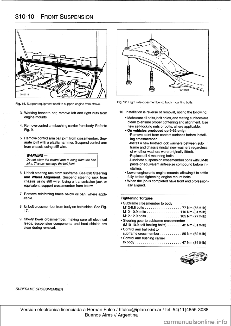
Fig
.
16
.
Supportequipment
used
to
support
engine
from
aboye
.
SUBFRAME
CROSSMEMBER
Fig
.
17
.
Right
side
crossmember-to
body
mounting
bolts
.
3
.
Working
beneath
car,
remove
left
and
right
nuts
from
10
.
Installation
is
reverse
ofremoval,
noting
the
followíng
:
engine
mounts
.
"
Make
sure
all
bolts,bolt
holes,
and
mating
surfaces
are
clean
to
ensure
proper
tightening
and
alignment
.
Use
4
.
Remove
control
arm
bushing
carrier
from
body
.
Refer
to
new
self-locking
nuts
or
bolts,
where
applicable
.
Fig
.
9
.
"
On
vehicles
produced
up
9-92
only
:
-Remove
paint
from
contact
surfaces
before
ínstall-
5
.
Remove
control
arm
ball
joint
from
crossmember
.
Sep-
ing
crossmember
.
arate
joint
with
a
plastic
hammer
.
Suspend
control
arm
-Install
4
new
toothed
lock
washersbetween
sub-from
chassis
using
stiff
wire
.
frame
and
chassis
(install
new
washers
regardless
of
whether
washers
were
originally
fitted)
.
WARNING-
-Replace
all
4
mounting
bolts
.
Do
not
allow
the
control
arm
to
hang
from
the
ball
-Lubrícate
suspension
crossmember
bolts
with
LM48
¡oint
.
This
can
damage
theball¡oint
.
paste
orequivalent
anti-seize
compound
before
ín-
stalling
.
6
.
Unbolt
steering
rack
from
subframe
.
See
320
Steering
"
Lower
engine
onto
enginemounts,
allowing
it
to
settle
and
Wheel
Alignment
.
Suspend
steering
rack
from
fully
before
tightening
engine
mount
bolts
.
chassis
using
stiff
wire
.
Using
a
transmission
jackor
"
When
thejob
is
completed
have
front
end
profession-
equivalent,
support
crossmember
from
below
.
ally
aligned
.
7
.
Remove
reinforcing
brace
below
oil
pan,
where
appli-
cable
.
Tightening
Torques
"
Subframe
crossmember
to
body
8
.
Unbolt
crossmemberfrom
body
on
both
sides
.
See
Fig
.
M12-8
.8
bolts
..................
.
77
Nm
(56
ft-Ib)
17
.
M12-10
.9
bolts
.................
110
Nm
(81
ft-Ib)
M12-12
.9
bolts
............
.
...
.
105
Nm
(77
ft-Ib)
9
.
Slowly
Lower
crossmember,
making
sure
all
electrical
"
Steering
gear
to
subframe
crossmember
teads,
suspension
components
and
heat
shields
are
(M10-10
.9
self-locking
bolts)
..
.
.
.
.
.
42
Nm
(31
ft-Ib)
clear
during
removal
.
"
Control
arm
balljoint
to
subframe
crossmember
...
.......
.
85
Nm
(62
ft-Ib)
"
Control
arm
bushing
carrier
to
body
..........
...
.
.....
.
..
..
47
Nm
(34
ft-Ib)
Page 268 of 759

320-2
STEERING
AND
WHEEL
ALIGNMENT
3
.
Carefully
remove
airbag
from
front
of
steering
wheel
.
See
721
Airbag
System
(SRS)
.
Store
airbag
unit
in
a
safe
place
.
WARNING-
Improper
handling
of
theaírbag
could
cause
seri-
ous
ínjury
.
Store
theaírbag
with
the
horn
pad
facing
up
.
If
stored
facing
down,
accidental
deployment
could
propel
it
vlolently
into
the
air,
causíng
ínjury
.
4
.
Remove
steering
wheel
center
bolt
.
Lightly
punch
mark
or
scribe
position
of
steering
wheel
to
steering
column
shaft
.
See
Fig
.
1
.
0012687
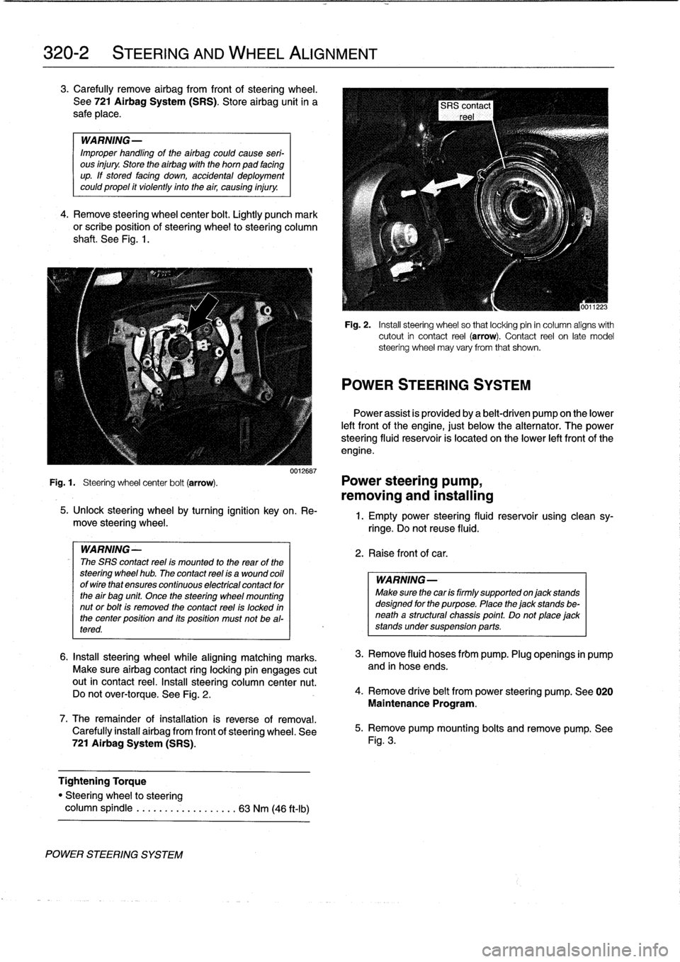
Fig
.
1
.
Steering
wheel
center
bolt
(arrow)
.
Power
steering
pump,
removing
and
installing
POWER
STEERING
SYSTEM
5
.
Unlock
steering
wheel
by
turning
ignition
key
on
.
Re-
move
steering
wheel
.
WARNING-
The
SRS
contact
reel
ís
mounted
to
the
rear
of
the
steering
wheel
hub
.
The
contact
reel
ís
a
wound
coil
ofwirethat
ensures
continuous
electrícal
contact
for
the
air
bag
unit
Once
the
steering
wheel
mounting
nut
or
bolt
is
removed
the
contact
reel
is
locked
in
the
center
position
and
its
position
must
not
be
al-
tered
.
6
.
Insta¡¡
steering
wheel
while
aligning
matching
marks
.
Make
sure
airbag
contact
ring
locking
pin
engages
cutout
in
contact
reel
.
Insta¡¡
steering
column
center
nut
.
Do
not
over-torque
.
See
Fig
.
2
.
7
.
The
remainder
ofinstallation
is
reverse
of
removal
.
Carefully
install
airbag
from
front
of
steering
wheel
.
See
721
Airbag
System
(SRS)
.
Tightening
Torque
"
Steering
wheel
to
steering
column
spindle
...
..
..
.
..........
63
Nm
(46
ft-Ib)
Fig
.
2
.
Insta¡¡
steering
wheel
so
that
locking
pin
in
column
aligns
with
cutout
in
contact
reel
(arrow)
.
Contact
reel
on
late
model
steering
wheel
may
vary
from
that
shown
.
POWER
STEERING
SYSTEM
Power
assist
is
províded
by
a
belt-driven
pump
on
the
lower
left
front
of
the
engine,
just
below
the
alternator
.
The
power
steering
fluid
resenroir
is
located
on
the
lower
left
front
of
the
engine
.
1
.
Empty
power
steering
fluid
reservoir
usingclean
sy-
ringe
.
Do
not
reuse
fluid
.
2
.
Raise
front
of
car
.
WARNING
Make
sure
thecar
is
firmly
supportedon
jack
stands
designed
for
the
purpose
.
Place
the
jack
stands
be-
neatha
structural
chassis
point
.
Do
not
place
jack
stands
undersuspension
parts
.
3
.
Remove
fluid
hoses
frbm
pump
.
Plug
openings
in
pump
and
in
hose
ends
.
4
.
Remove
drive
belt
from
power
steering
pump
.
See
020
Maintenance
Program
.
5
.
Remove
pump
mounting
bolts
and
remove
pump
.
See
Fig
.
3
.