1991 MITSUBISHI MONTERO oil
[x] Cancel search: oilPage 58 of 1333

against crankshaft shoulder. Use Thin Wall Socket (J-9399) and Clutch
Hub Holder (J-25030). Tighten shaft nut to 96-192 INCH lbs.
(11-22 N.m). Spin pulley rotor by hand to ensure rotor is not rubbing
on clutch drive plate. See Fig. 8.
HARRISON V5 5-CYLINDER SHAFT SEAL R & I
Removal
Discharge refrigerant from system using approved refrigerant
recovery/recycling equipment. See SERVICING PRECAUTIONS at beginning
of article. Remove clutch plate assembly. Remove shaft seal snap ring.
Thoroughly clean inside of compressor neck area around shaft and seal.
Engage tangs of Seal Remover/Installer (J-23128-A) into recessed
portion of seal and remove seal. Remove and discard seal "O" ring from
compressor neck. Thoroughly clean inside of compressor neck and "O"
ring groove.
Installation
1) Coat new "O" ring with refrigerant oil and install on "O"
ring installer (J-33011). Install "O" ring into groove in compressor
neck. Attach new seal to Seal Remover/Installer (J-23128-A). Dip seal
in clean refrigerant oil.
2) Place Seal Protector (J-34614) over compressor shaft. Pus\
h
new seal over shaft protector. Install new snap ring with flat side
against seal. Install clutch plate assembly.
Fig. 8: Exploded View of Harrison V5 5-Cylinder Compressor
Courtesy of General Motors Co.
Page 59 of 1333

HITACHI 5 & 6-CYL CLUTCH R & I
Removal
1) Using Clutch Holder (KV99412302), hold clutch hub. Remove\
shaft nut from shaft. Using Clutch Hub Remover (KV994C5780), remove
clutch hub.
2) Pry inner snap ring off. Remove pulley and bearing
assembly. If assembly cannot be removed by hand, use Pulley and
Bearing Removers (KV994C5781 and KV994C5782).
3) Remove clamping screws that secure coil assembly leads.
Remove inner snap ring from coil assembly. Remove coil assembly from
front cover. See Fig. 9.
Inspection
Check friction surfaces of clutch for damage due to excessive
heat, or excessive grooving due to slippage. Replace compressor
components as necessary. Oil or dirt on friction surfaces should be
cleaned with a solvent and a dry rag. Check coil for binding, shorted
or open leads.
Installation
1) Install coil assembly on compressor. Properly position
terminals. Using snap ring pliers, install snap ring. Using a plastic
mallet, drive pulley and bearing assembly onto neck of front cover.
Turn pulley, making sure that there is no noise and that rotation is
free. Ensure there is no pulley play.
2) Using snap ring pliers, install inner snap ring. Remove
all oil from clutch pulley. Fit key and clutch hub to shaft. Select
adjusting spacer which gives the correct clearance between pulley and
clutch hub.
3) Coat shaft nut with Loctite and install. Using a feeler
gauge, measure clutch hub-to-pulley clearance. Clearance should be .
020-.031" (.5-.8 mm). If specified clearance is not obtained, replace
adjusting spacer and readjust.
4) When replacing compressor clutch assembly, DO NOT forget
break-in operation. This is accomplished by engaging and disengaging
clutch 30 times.
Page 60 of 1333

Fig. 9: Hitachi 6-Cylinder Compressor (5-Cylinder Similar)
Courtesy of Nissan Motor Co., U.S.A.
HITACHI 5 & 6-CYL SHAFT SEAL R & I
NOTE: Check compressor refrigerant oil level when replacing seals.
See COMPRESSOR REFRIGERANT OIL CHECKING article in this
section.
Removal
1) Drain oil from suction port, measure oil drained and
discard oil. Remove clutch hub, pulley, bearing assembly and coil
assembly. See HITACHI 5 & 6-CYLINDER CLUTCH R & I in this article.
2) Using snap ring pliers, remove retainer ring. Remove key
and plug low and high pressure openings of compressor with Plugs
(KV994C4531, KV994C4532 and KV994C4559).
3) Insert Adapter (KV994C1552) into hole in middle of blind
Page 63 of 1333

ring and carbon seal contact surface of shaft seal seat for damage.
Make sure that "O" ring contact surface on front cover is not damaged.
Make sure refrigerant oil is applied to oil seal in shaft seal seat.
Installation
1) To install, reverse removal procedure. Ensure shaft seal
contact surface is free of dirt. Lubricate with refrigerant oil. Cap
end of compressor shaft.
2) Using Guard (KV994C1143), insert shaft seal. Be sure shaf\
t
seal case is aligned with shaft. Apply force to turn seal to left and
right. Ensure shaft seal seats properly in shaft cut-out.
3) Fit "O" ring to outside groove of shaft seal seat. Ensure
"O" ring seats properly. Apply refrigerant oil on contact surfaces and
around shaft seal seat. Lightly coat surface of shaft with refrigerant
oil.
4) Install key on compressor shaft. Using snap ring pliers,
compress retainer ring and fit retainer ring into front cover. Seat
retainer ring firmly in groove. Thoroughly wipe grease or oil from
shaft surface.
5) Connect Installer (KV99412329) to shaft of compressor, an\
d
turn shaft 5 or 6 times in a clockwise direction to seat seal. See
REFRIGERANT OIL & R-12 SPECIFICATIONS chart in this section for system
capacities.
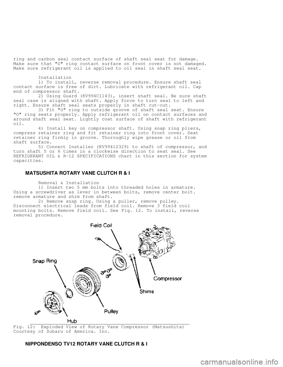
MATSUSHITA ROTARY VANE CLUTCH R & I
Removal & Installation
1) Insert two 5 mm bolts into threaded holes in armature.
Using a screwdriver as lever in between bolts, remove center bolt.
remove armature and shim from shaft.
2) Remove snap ring. Using a puller, remove pulley.
Disconnect electrical leads from field coil. Remove 3 field coil
mounting bolts. Remove field coil. See Fig. 12. To install, reverse
removal procedure.
Fig. 12: Exploded View of Rotary Vane Compressor (Matsushita)
Courtesy of Subaru of America. Inc.
NIPPONDENSO TV12 ROTARY VANE CLUTCH R & I
Page 65 of 1333

Removal
1) Remove A/C compressor. Remove pressure plate shaft bolt
using socket wrench and Clutch Stopper (07112-76060). Install Clutch
Remover (07112-66040) on pressure plate. Using clutch stopper and
socket wrench, rotate clutch remover to remove pressure plate.
2) Remove shims from pressure plate. Remove snap ring from
compressor. Tap rotor off shaft with plastic hammer. Disconnect stator
wire from housing. Remove snap ring from inside stator. Remove stator.
See Fig. 12 .
CAUTION: DO NOT damage pulley when tapping on rotor.
Installation
To install, reverse removal procedure. Ensure snap rings are
installed with beveled side up. tighten shaft bolt to 10 ft. lbs.
(14 N.m). Ensure clutch clearance is .014-.026" (.36-66 mm). adjust
clearance by adding or subtracting shims as necessary.
NIPPONDENSO 6 & 10-CYL SHAFT SEAL R & I
NOTE: Check compressor refrigerant oil level when replacing seals.
See COMPRESSOR OIL CHECKING article in the AIR CONDITIONING &
HEAT section.
Removal
1) Hold clutch hub stationary and remove center nut. Screw
remover into center of hub. Turn center bolt to remove pressure plate.
2) Remove shims from shaft. Remove snap ring from inside of
pulley. Tap pulley off of shaft with plastic mallet. Be careful not to
distort pulley while removing.
3) Disconnect clutch coil wires from compressor housing.
remove snap ring inside coil and lift coil off compressor. Pry dust
seal out from around compressor shaft (if equipped).
4) Place shaft key remover on shaft and turn to remove key.
Remove drain plug (if equipped). Remove service valves-to-compressor
body bolts. Remove valves. Discard "O" rings. Drain oil out of
compressor.
5) Remove 6 through bolts from front head of compressor and
discard washers. Tap head loose from compressor; be careful not to
scratch sealing surfaces. remove snap ring (if equipped) from front
housing. Press seal plate out. Remove seal from shaft. See Fig. 14.
Installation
1) Lubricate shaft seal with clean refrigerant oil and place
on compressor shaft. Lubricate seal plate and "O" ring (if equipped)
and install in front housing. Install snap ring (if equipped).
2) Place front housing on compressor body. Install through
bolts with new washers. Tighten bolts evenly and alternately to
18 ft. lbs. (24 N.m). Install shaft key using installer and plastic
mallet. Insert dust seal into front of compressor.
3) Install drain plug with new gasket. Add correct amount of
refrigerant oil to compressor. If service valves were removed, coat
new "O" rings with refrigerant oil and install service valves.
4) Place clutch coil on compressor and install snap ring.
Install shims on shaft to adjust pressure plate-to-rotor clearance to
.016-.028" (.41-.71 mm). Tighten shaft nut to 12 ft. lbs. (16 N.m).
Page 67 of 1333

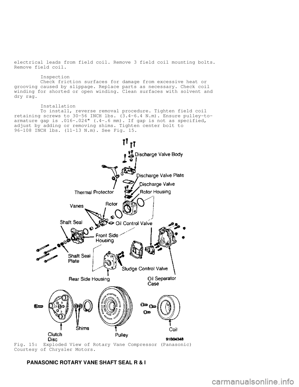
electrical leads from field coil. Remove 3 field coil mounting bolts.
Remove field coil.
Inspection
Check friction surfaces for damage from excessive heat or
grooving caused by slippage. Replace parts as necessary. Check coil
winding for shorted or open winding. Clean surfaces with solvent and
dry rag.
Installation
To install, reverse removal procedure. Tighten field coil
retaining screws to 30-56 INCH lbs. (3.4-6.4 N.m). Ensure pulley-to-
armature gap is .016-.024" (.4-.6 mm). If gap is not as specified,
adjust by adding or removing shims. Tighten center bolt to
96-108 INCH lbs. (11-13 N.m). See Fig. 15.
Fig. 15: Exploded View of Rotary Vane Compressor (Panasonic)
Courtesy of Chrysler Motors.
PANASONIC ROTARY VANE SHAFT SEAL R & I
Page 68 of 1333

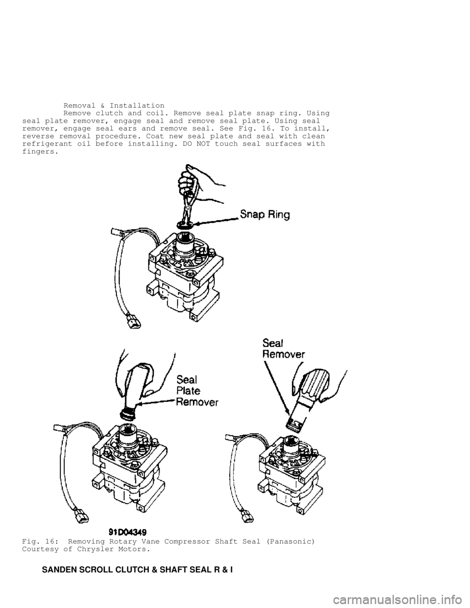
Removal & Installation
Remove clutch and coil. Remove seal plate snap ring. Using
seal plate remover, engage seal and remove seal plate. Using seal
remover, engage seal ears and remove seal. See Fig. 16. To install,
reverse removal procedure. Coat new seal plate and seal with clean
refrigerant oil before installing. DO NOT touch seal surfaces with
fingers.
Fig. 16: Removing Rotary Vane Compressor Shaft Seal (Panasonic)
Courtesy of Chrysler Motors.
SANDEN SCROLL CLUTCH & SHAFT SEAL R & I
Page 69 of 1333

NOTE: Check compressor refrigerant oil level when replacing seals.
Removal
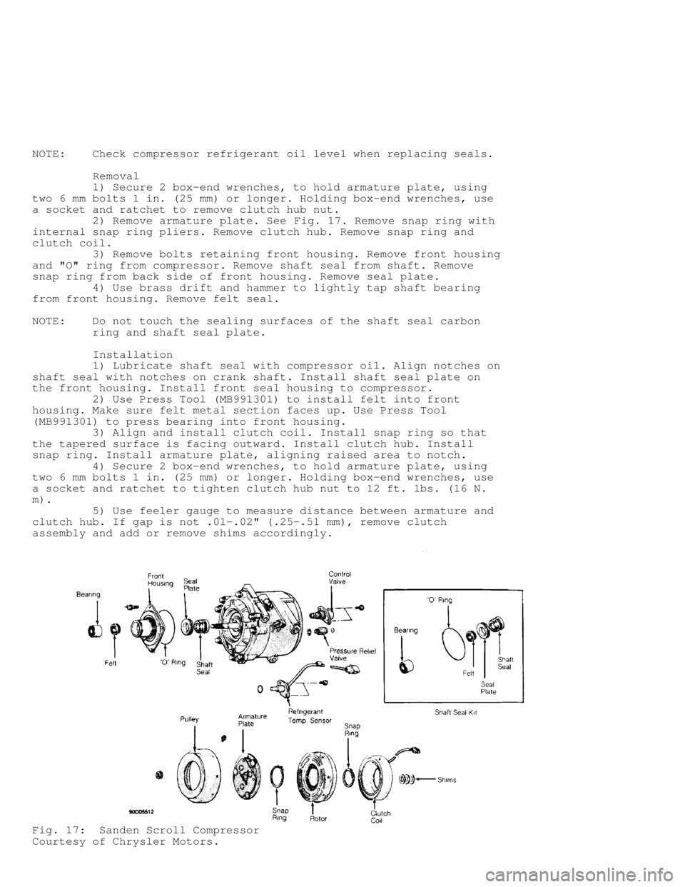
1) Secure 2 box-end wrenches, to hold armature plate, using
two 6 mm bolts 1 in. (25 mm) or longer. Holding box-end wrenches, use
a socket and ratchet to remove clutch hub nut.
2) Remove armature plate. See Fig. 17. Remove snap ring with
internal snap ring pliers. Remove clutch hub. Remove snap ring and
clutch coil.
3) Remove bolts retaining front housing. Remove front housing
and "O" ring from compressor. Remove shaft seal from shaft. Remove
snap ring from back side of front housing. Remove seal plate.
4) Use brass drift and hammer to lightly tap shaft bearing
from front housing. Remove felt seal.
NOTE: Do not touch the sealing surfaces of the shaft seal carbon
ring and shaft seal plate.
Installation
1) Lubricate shaft seal with compressor oil. Align notches on
shaft seal with notches on crank shaft. Install shaft seal plate on
the front housing. Install front seal housing to compressor.
2) Use Press Tool (MB991301) to install felt into front
housing. Make sure felt metal section faces up. Use Press Tool
(MB991301) to press bearing into front housing.
3) Align and install clutch coil. Install snap ring so that
the tapered surface is facing outward. Install clutch hub. Install
snap ring. Install armature plate, aligning raised area to notch.
4) Secure 2 box-end wrenches, to hold armature plate, using
two 6 mm bolts 1 in. (25 mm) or longer. Holding box-end wrenches, use
a socket and ratchet to tighten clutch hub nut to 12 ft. lbs. (16 N.
m).
5) Use feeler gauge to measure distance between armature and
clutch hub. If gap is not .01-.02" (.25-.51 mm), remove clutch
assembly and add or remove shims accordingly.
Fig. 17: Sanden Scroll Compressor
Courtesy of Chrysler Motors.