Page 618 of 1333
article in GENERAL INFORMATION.
IDENTIFYING WIRING DIAGRAM SYMBOLS
NOTE: Standard wiring symbol are used in these diagrams. The
illustration below will help clarify any symbols that are
not easily understood at a glance. Most components are
labeled "Motor", "Switch" or "Relay" in addition to being
drawn with the standard symbol.
Fig. 1: Identifying Wiring Diagram Symbols
Page 619 of 1333

WIRING DIAGRAM COMPONENT LOCATIONS
When trying to locate a component in a wiring diagram and you
don't know the specific system where it is located, use this handy
component locator to find the system wiring diagram in which the
component is located. Then, go to that system and locate the component
within the wiring diagram.
For example, if you don't know the specific system in which
the ignition switch is located, look up ignition switch in the wiring
diagram component location tables and go to the appropriate wiring
diagram(s) which contain either full or partial views of the ignition
switch. The full view of the ignition switch is located in Power
Distribution.
The first listing for the component will be the full or most
complete view of the component. Additional listings will be partial
views of the component. Not all components are used on all models.
All components will have a partial view in Ground
Distribution and Power Distribution. Data Link Connectors show
connecting circuits between modules. Alternate names for components
may be listed in wiring diagram component locations tables.
WIRING DIAGRAM COMPONENT LOCATIONS TABLE
������������������\
������������������\
������������������\
������������������\
������������������\
������������������\
������������������\
�������������
Component Wiring Diagram
ABS Electronic Control Unit ....................... Anti-Lock Brakes
Data Link Connectors
ABS Hydraulic Unit ................................ Anti-Lock Brakes
Acceleration Sensor ............................... Anti-Lock Brakes
Accessory Delay Relay ................................ Power Windows
A/C Compressor Clutch Relay ..................... Engine Performance
A/C Sensor ...................................... Engine Performance
A/C Pressure Switch ............................. Engine Performance
Adaptive Lamp Control Module ....................... Exterior Lights
Air Bag(s) ................................ Air Bag Restraint System\
Air Bag Module ............................ Air Bag Restraint System
Air Bag Sensor(s) ......................... Air Bag Restraint System\
Air Injection Pump Relay ........................ Engine Performance
Air Temperature Sensor ............................ Overhead Console
Alternator (Generator) ..................... Generators & Regulators\
Anti-Theft Control Module ........................ Anti-Theft System
Starters
Autolamp Control Relay ........................... Headlight Systems
Daytime Running Lights
Automatic Shutdown (ASD) Relay .................. Engine Performance\
Generators & Regulators
Autostick Switch ................................ Engine Performance
Auxiliary Battery Relay .................... Generators & Regulators
Back-Up Lights ...................................... Back-Up Lights
Exterior Lights
Barometric (BARO) Pressure Sensor ............... Engine Performance\
Battery ......................................... Power Distribution
Battery Temperature Sensor ...................... Engine Performance
Body Control Module .......................... Body Control Computer
Anti-Theft System
Daytime Running Lights
Engine Performance
Headlight Systems
Warning Systems
Boost Control Solenoid .......................... Engine Performance
Boost Sensor .................................... Engine Performance
Brake Fluid Level Switch .................. Analog Instrument Panels
Page 634 of 1333
. Speedometer cable
length varies with transmission type.
Removal")
NOTE: When routing speedometer cable, DO NOT bend cable sharply.
Minimum bending radius is 6" (150 mm). Speedometer cable
length varies with transmission type.
Removal
Disconnect speedometer cable from transmission or transaxle.
Remove instrument cluster from instrument panel. See
INSTRUMENT CLUSTER under REMOVAL & INSTALLATION. Disconnect
speedometer cable from instrument cluster and/or adapter (if
equipped). Remove speedometer cable from firewall grommet.
Installation
Install new cable. Insert cable until stopper seats properly
in groove on rear of speedometer housing. Pull speedometer cable
through firewall grommet until cable marking is visible from engine
compartment. Install adapter onto speedometer cable (if equipped).
Install instrument cluster. See INSTRUMENT CLUSTER under REMOVAL &
INSTALLATION. Install cable onto transmission or transaxle. Check for
proper operation.
NOTE: An improperly installed cable can cause fluctuating meter,
noise or damaged harness inside instrument panel.
WIRING DIAGRAMS
See appropriate chassis wiring diagram in the WIRING DIAGRAMS
Section.
Page 639 of 1333
\003
L - W IR IN G D IA G RAM S
�
1991 M it s u bis h i M onte ro
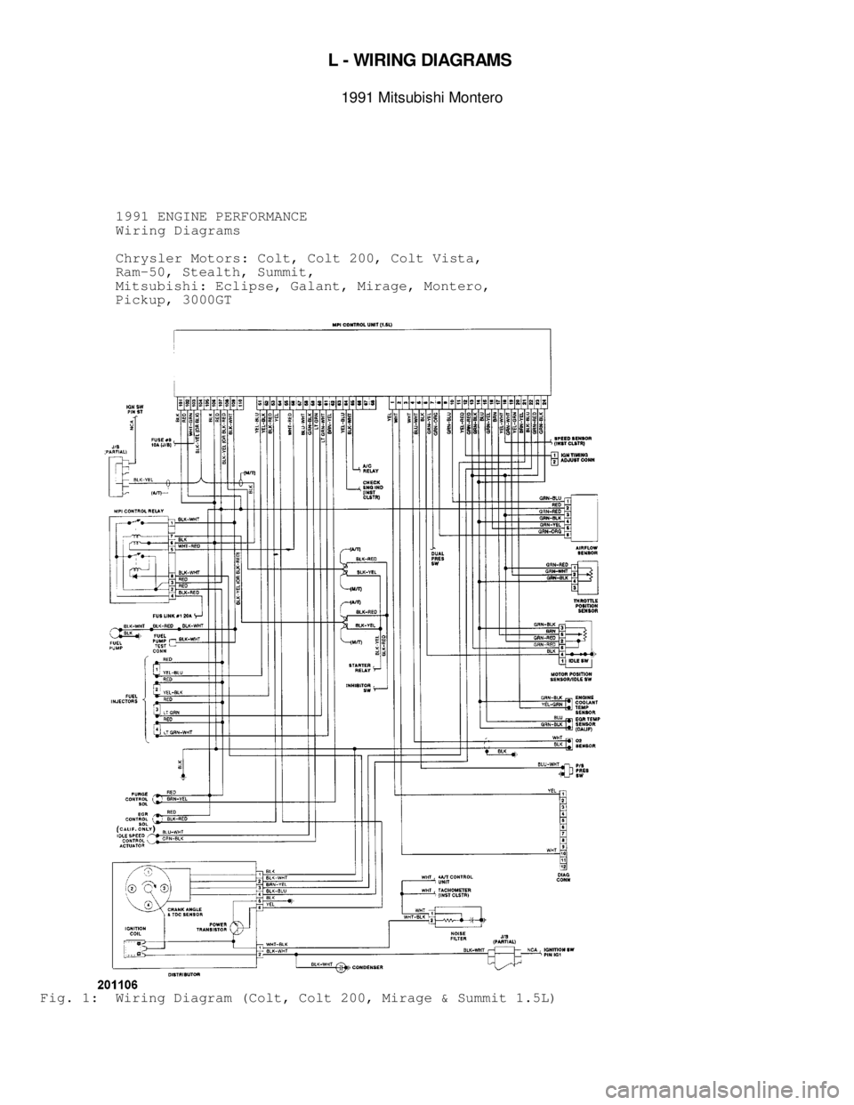
1991 ENGINE PERFORMANCE
Wiring Diagrams
Chrysler Motors: Colt, Colt 200, Colt Vista,
Ram-50, Stealth, Summit,
Mitsubishi: Eclipse, Galant, Mirage, Montero,
Pickup, 3000GT
Fig. 1: Wiring Diagram (Colt, Colt 200, Mirage & Summit 1.5L)
Page 640 of 1333
Fig. 2: Wiring Diagram (Colt Vista 2.0L)
Page 641 of 1333
Fig. 3: Wiring Diagram (Eclipse 1.8L)
Page 642 of 1333
Fig. 4: Wiring Diagram (Eclipse 2.0L)
Page 643 of 1333
Fig. 5: Wiring Diagram (Eclipse 2.0L Turbo)

")
")
")
")