Page 1175 of 1333

oil filter/screen, note length and location of all bolts.
TRANSAXLE (EXCEPT MONTERO, PICKUP & RAM-50)
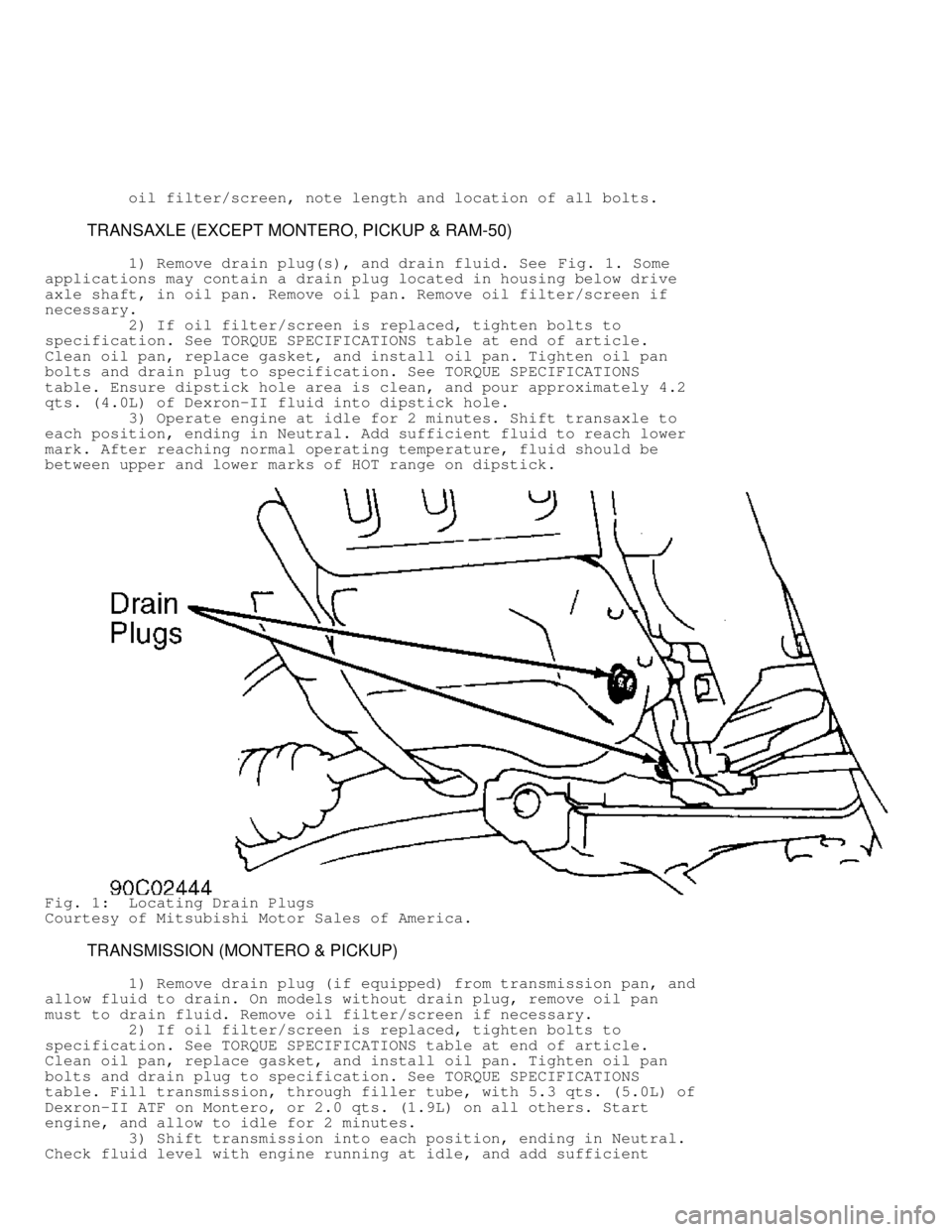
1) Remove drain plug(s), and drain fluid. See Fig. 1. Some
applications may contain a drain plug located in housing below drive
axle shaft, in oil pan. Remove oil pan. Remove oil filter/screen if
necessary.
2) If oil filter/screen is replaced, tighten bolts to
specification. See TORQUE SPECIFICATIONS table at end of article.
Clean oil pan, replace gasket, and install oil pan. Tighten oil pan
bolts and drain plug to specification. See TORQUE SPECIFICATIONS
table. Ensure dipstick hole area is clean, and pour approximately 4.2
qts. (4.0L) of Dexron-II fluid into dipstick hole.
3) Operate engine at idle for 2 minutes. Shift transaxle to
each position, ending in Neutral. Add sufficient fluid to reach lower
mark. After reaching normal operating temperature, fluid should be
between upper and lower marks of HOT range on dipstick.
Fig. 1: Locating Drain Plugs
Courtesy of Mitsubishi Motor Sales of America.
TRANSMISSION (MONTERO & PICKUP)
1) Remove drain plug (if equipped) from transmission pan, an\
d
allow fluid to drain. On models without drain plug, remove oil pan
must to drain fluid. Remove oil filter/screen if necessary.
2) If oil filter/screen is replaced, tighten bolts to
specification. See TORQUE SPECIFICATIONS table at end of article.
Clean oil pan, replace gasket, and install oil pan. Tighten oil pan
bolts and drain plug to specification. See TORQUE SPECIFICATIONS
table. Fill transmission, through filler tube, with 5.3 qts. (5.0L) of\
Dexron-II ATF on Montero, or 2.0 qts. (1.9L) on all others. Start
engine, and allow to idle for 2 minutes.
3) Shift transmission into each position, ending in Neutral.
Check fluid level with engine running at idle, and add sufficient
Page 1176 of 1333

fluid to bring level to lower mark of dipstick if necessary. Recheck
fluid level after transmission is at normal operating temperature.
TRANSFER CASE
Drain plug is located on bottom of transfer case. Change
drain plug gasket whenever fluid is changed. On 3000GT, lubricant
level should be approximately .5" (13 mm) below fill hole on side of
transfer case. On all others models, lubricant level should be to
bottom of fill hole on side of transfer case.
HYDRAULIC CONTROL PRESSURE ADJUSTMENTS
LINE PRESSURE CHECK (EXCEPT MONTERO & PICKUP)
1) Set parking brake. Place shift lever in Neutral position.
Attach engine tachometer. Remove line pressure port plug located above
front transaxle shaft, forward of governor pressure port plug. On
Precis, line pressure port is located below bell housing, at front of
transaxle oil pan. Using appropriate adapter, attach pressure gauge.
2) Start engine, and bring to operating temperature. With
gear selector in Drive position, bring engine speed to 2500 RPM. Pull
throttle control cable (if equipped) wide open at transaxle side.
3) Line pressure should be 98-100 psi (6.9-7.0 kg/cm
�) on
Mirage, or 124-127 psi (8.7-8.9 kg/cm�) on all others. If line
pressure is not to specification, proceed to LINE PRESSURE ADJUSTMENT.
LINE PRESSURE ADJUSTMENT (EXCEPT MONTERO & PICKUP)
1) Drain transaxle fluid. Remove oil pan. Disconnect throttle
control cable from throttle cam. Remove oil temperature sensor (if
equipped). Disconnect solenoid connector. On some models, it may be
necessary to push solenoid wire harness connector and grommet into
transaxle case.
2) Remove oil filter screen and plate. Noting location and
length of bolts, remove valve body. DO NOT drop internal parts. Adjust
line pressure by turning regulator valve adjusting screw.
3) Turn adjusting screw counterclockwise to increase pressure
or clockwise to decrease pressure. One complete turn of adjusting
screw changes line pressure as follows.
* 3.7 psi (.26 kg/cm
�) on Mirage with F3A21 Transaxle
* 5.4 psi (.39 kg/cm�) on Precis
* 54 psi (3.8 kg/cm�) on all others
4) After adjustment, reverse removal procedure to install.
Refill transaxle.
LINE PRESSURE (MONTERO)
1) Remove plug from line pressure take-off port located
behind transmission shift control lever. Install Hydraulic Pressure
Meter (MD998330) with Adapter (MD998206).
2) Place vehicle on dynamometer. Apply parking brake and
start engine. With brake applied, place transmission in Drive. Note
pressure at idle. Pressure should be 74-85 psi (5.2-6.0 kg/cm
�).
3) Raise engine RPM to stall speed (2100-2400 RPM). Note lin\
e
pressure. Pressure should be 156-185 psi (11.0-13.0 kg/cm
�).
4) Shift transmission into Reverse with brake applied. At
idle, pressure should be 112-130 psi (7.9-9.1 kg/cm
�). Raise engine
RPM to stall speed (2100-2400 RPM). Note line pressure. Pressure
should be 227-285 psi (16.0-20.0 kg/cm
�). If readings are not to
Page 1184 of 1333

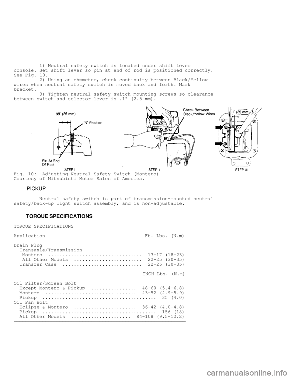
1) Neutral safety switch is located under shift lever
console. Set shift lever so pin at end of rod is positioned correctly.
See Fig. 10 .
2) Using an ohmmeter, check continuity between Black/Yellow
wires when neutral safety switch is moved back and forth. Mark
bracket.
3) Tighten neutral safety switch mounting screws so clearance
between switch and selector lever is .1" (2.5 mm).
Fig. 10: Adjusting Neutral Safety Switch (Montero)
Courtesy of Mitsubishi Motor Sales of America.
PICKUP
Neutral safety switch is part of transmission-mounted neutral
safety/back-up light switch assembly, and is non-adjustable.
TORQUE SPECIFICATIONS
TORQUE SPECIFICATIONS������������������\
������������������\
������������������\
������������������\
������������������\
������������������\
�����������
Application Ft. Lbs. (N.m)
Drain Plug
Transaxle/Transmission
Montero ................................. 13-17 (18-23)
All Other Models ........................ 22-25 (30-35)
Transfer Case ............................ 22-25 (30-35)
INCH Lbs. (N.m)
Oil Filter/Screen Bolt
Except Montero & Pickup ................ 48-60 (5.4-6.8)
Montero ................................ 43-52 (4.9-5.9)
Pickup ........................................ 35 (4.0)
Oil Pan Bolt
Eclipse & Montero ...................... 36-42 (4.0-4.8)
Pickup ........................................ 156 (18)
All Other Models ..................... 84-108 (9.5-12.2)
������������������\
������������������\
������������������\
������������������\
������������������\
������������������\
�����������