1991 MITSUBISHI MONTERO cruise control
[x] Cancel search: cruise controlPage 231 of 1333
 System input tests cycle each cruise control switch and
sensor. Use analog voltmeter or Multi-Use Tester (MB991341) for system\
input check. Use multi-use tester according to operating in")
2) System input tests cycle each cruise control switch and
sensor. Use analog voltmeter or Multi-Use Tester (MB991341) for system\
input check. Use multi-use tester according to operating instructions
provided with tester. Connect leads of analog voltmeter between cruise
control terminal and ground terminal of self-diagnostic connector. See
Fig. 6.
3) Turn ignition on and check items No. 1-3 on INPUT CODE
CHART. See Fig. 9 0r 10. Start engine and check items No. 4 and 5 on
INPUT CODE CHART. To display results of each input check, press SET
switch while holding RESUME switch in ON position. Read codes. Codes
will display if circuit tested is okay.
1992
1) System input tests should be performed if no trouble codes
are stored when performing SELF-DIAGNOSTICS. System input tests cycle
each cruise control switch and sensor.
2) Use Multi-Use Tester (MB991341) for system input check.
Use multi-use tester according to operating instructions provided with
tester. Connect leads of analog voltmeter between cruise control
terminal and ground terminal of self-diagnostic connector. See Fig. 6.
Turn ignition switch to ON position. Follow INPUT CODE CHART sequence.
See Fig. 9 or 10.
3) To display results of input check, move SET switch to ON
position. Then turn MAIN switch to ON position. Within one second,
activate RESUME switch. Codes will display if circuit tested is okay.
Fig. 9: 1991 Input Code Chart
Courtesy of Mitsubishi Motor Co.
Page 239 of 1333

Test No. 1 (Power & Ground Circuit)
1) Turn ignition on. When cruise control main switch is
turned to ON position, battery voltage should be present on terminal
No. 7 of cruise control unit connector.
2) If voltage is not present, check fuse No. 3 and replace as
necessary. If fuse is okay, check and repair harness as necessary.
Terminal No. 10 should be grounded at all times. If terminal No. 10 is
not grounded, repair harness.
Test No. 2 (Set Switch Circuits)
When set switch is turned to ON position, voltage should not
be present on terminal No. 5 of cruise control unit. When set switch
is turned to OFF position, battery voltage should be present on
terminal No. 5 of cruise control unit. If circuit does not test
correctly, replace switch as necessary or repair harness.
Test No. 3 (Resume Switch Circuit)
When resume switch is turned to ON position, voltage should
not be present on terminal No. 4 of cruise control unit. When resume
switch is turned to OFF position, battery voltage should be present on
terminal No. 4 of cruise control unit. If circuit does not test
correctly, replace switch as necessary or repair harness.
Test No. 4 (Vehicle Speed Sensor Circuit)
When vehicle moves slowly, voltage should alternate from zero
volts to 3-5 volts at terminal No. 15 of cruise control unit. If
circuit does not test correctly, replace sensor as necessary or repair
harness.
Test No. 5 (Actuator Circuit)
1) When cruise control main switch is in On position, voltage
should not be present on terminal No. 8 of cruise control unit.
2) When vehicle is accelerated using resume switch, voltage
should not be present on terminal No. 9 of cruise control unit. When
vehicle is coasting by using set switch, battery voltage should be
present on terminal No. 9.
3) When vehicle is accelerated using resume switch, battery
voltage should be present on terminal No. 20 of cruise control unit.
When vehicle is coasting by using set switch, voltage should not be
present on terminal No. 20 of cruise control unit. If circuit does not
test correctly, replace actuator as necessary or repair harness.
Test No. 6 (Stoplight Switch Circuit)
1) When brake pedal is pressed, battery voltage should be
present on terminal No. 3 of cruise control unit. If voltage is not
present, adjust or replace brake switch.
2) Battery voltage should be present at all times on terminal
No. 11 of cruise control unit. If voltage is not present, check fuse
no. 7. If fuse is okay, repair harness.
Test No. 7 (Inhibitor Switch Circuit)
1) When gear shift lever is moved to Neutral or Park
position, voltage should not be present on terminal No. 2 of cruise
control unit.
2) When gear shift lever is moved to any other position,
battery voltage should be present on terminal No. 2 of cruise control
unit. If circuit does not test correctly, replace switch as necessary
or repair harness.
Test No. 8 (Clutch Switch Circuit)
When clutch pedal is pressed, battery voltage should be
present at terminal No. 1 of cruise control unit. If circuit does not
Page 240 of 1333

test correctly, replace switch as necessary or repair harness.
Test No. 9 (Overdrive Switch Circuit)
When overdrive switch is pushed to ON position, battery
voltage should be present on terminals No. 13 and 14 of cruise control
unit. If circuit does not test correctly, replace switch as necessary
or repair harness.
Fig. 17: 1991 Cruise Control Unit Connector
Courtesy of Mitsubishi Motor Co.
Fig. 18: 1991 Instrument Cluster Connector
Courtesy of Mitsubishi Motor Co.
Page 241 of 1333
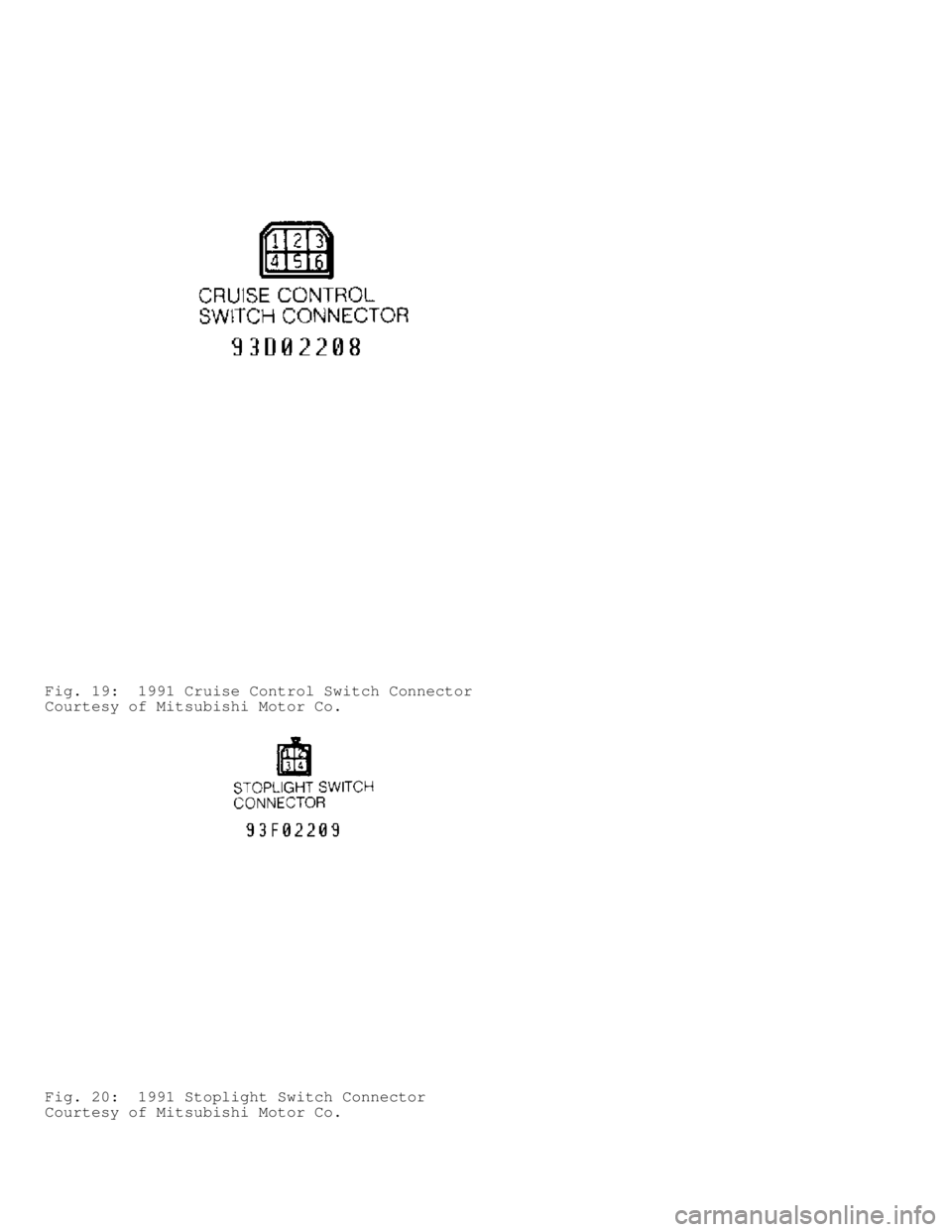
Fig. 19: 1991 Cruise Control Switch Connector
Courtesy of Mitsubishi Motor Co.
Fig. 20: 1991 Stoplight Switch Connector
Courtesy of Mitsubishi Motor Co.
Page 242 of 1333

Fig. 21: 1991 Acturator Connector
Courtesy of Mitsubishi Motor Co.
CIRCUIT TESTS (1992)
NOTE: To identify circuit connector terminals, See Figs. 22-29.
For wiring diagram, See appropriate chassis wiring diagram in
the WIRING DIAGRAMS Section.
Test No. 1 (Power & Ground Circuit)
1) Turn ignition on. When cruise control main switch is
turned to ON position, battery voltage should be present on terminal
No. 2 of cruise control unit connector.
2) If voltage is not present, check fuse No. 11 and replace
as necessary. If fuse is okay, check and repair harness as necessary.
Terminal No. 8 should be grounded at all times. If terminal No. 8 is
not grounded, repair harness.
Test No. 2 (Set Switch Circuits)
When set switch is turned to ON position, 3 volts should be
present on terminal No. 18 of cruise control unit. When set switch is
turned to OFF position, voltage should not be present on terminal No.
18 of cruise control unit. If circuit does not test correctly, replace
switch as necessary or repair harness.
Test No. 3 (Resume Switch Circuit)
When resume switch is turned to ON position, 6 volts should
be present on terminal No. 18 of cruise control unit. When resume
switch is turned to OFF position, voltage should not be present on
terminal No. 18 of cruise control unit. If circuit does not test
correctly, replace switch as necessary or repair harness.
Test No. 4 (Cancel Switch Circuit)
When cancel switch is turned to On position, battery voltage
should be present on terminal No. 18 of cruise control unit. When
cancel switch is in Off position, voltage should not be present on
terminal No. 18 of cruise control unit. If circuit does not test
correctly, replace switch as necessary or repair harness.
Page 243 of 1333

Test No. 5 (Vehicle Speed Sensor Circuit)
When vehicle moves slowly, 0-2 or more volts should alternate
at terminal No. 19 of cruise control unit. If circuit does not test
correctly, replace sensor as necessary or repair harness.
Test No. 6 (Vacuum Pump Circuit)
1) When cruise system is in deceleration or release mode,
battery voltage should be present on terminals No. 26 and 13 of cruise
control unit. If circuit does not test correctly, replace vacuum pump
as necessary or repair harness.
2) When cruise system is in release mode, battery voltage
should be present on terminal No. 12 of cruise control unit. When
cruise system is in hold mode, voltage on terminals No. 12, 13 and 26
will go from battery voltage to zero volts depending on driving
conditions. If circuit does not test correctly, replace vacuum pump as
necessary or repair harness.
Test No. 7 (Stoplight Switch Circuit)
When brake pedal is pressed, battery voltage should be
present on terminal No. 15 of cruise control unit. If voltage is not
present, adjust or replace brake switch. If circuit does not test
correctly, replace switch as necessary or repair harness.
Test No. 8 (Clutch Switch Circuit)
When clutch pedal is pressed, battery voltage should be
present at terminal No. 1 of cruise control unit. If circuit does not
test correctly, replace switch as necessary or repair harness.
Test No. 9 (Inhibitor Switch Circuit)
When transmission is in Neutral position, battery voltage
should be present on terminal No. 1 of cruise control unit. If circuit
does not test correctly, replace switch as necessary or repair
harness.
Test No. 10 (Overdrive Switch Circuit)
When overdrive switch is pushed to ON position, battery
voltage should be present on terminal No. 11 of cruise control unit.
If circuit does not test correctly, replace switch as necessary or
repair harness.
Test No. 11 (Idle Switch & Throttle Position Sensor Circuit)
1) When accelerator pedal is pressed, 4.5-5.5 volts should be
present on terminal No. 4 (idle switch) of cruise control unit. When
accelerator pedal is released, voltage should not be present on
terminal No. 4 of cruise control unit.
2) When accelerator pedal is pressed to wide open throttle,
4.0-5.5 volts should be present on terminal No. 5 (throttle position
sensor) of cruise control unit. When accelerator pedal is released, .
5-.7 volts should be present on terminal No. 5 of cruise control unit.
If circuit does not test correctly, replace sensor as necessary or
repair harness.
Fig. 22: 1992 Cruise Control Unit Connector
Courtesy of Mitsubishi Motor Co.
Page 244 of 1333
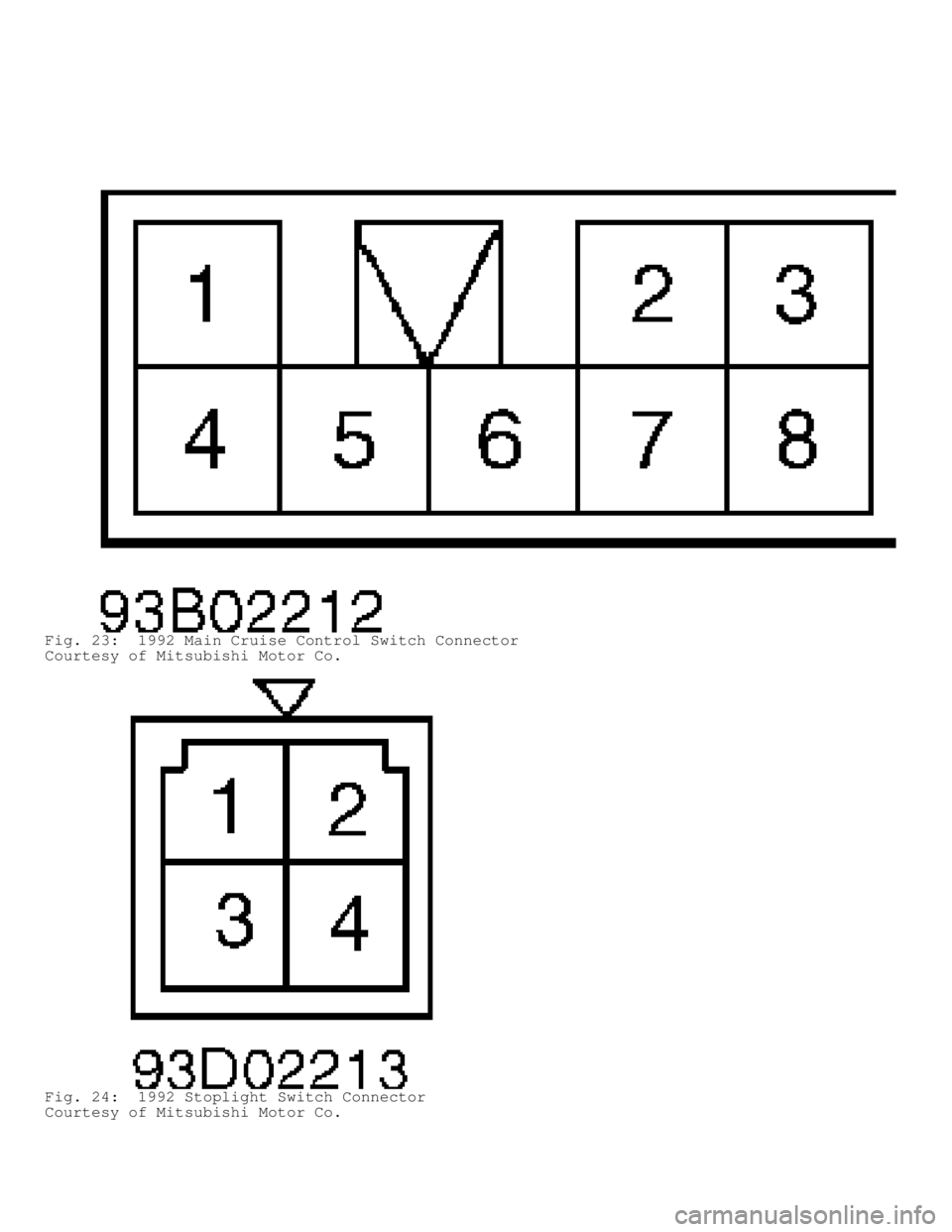
Fig. 23: 1992 Main Cruise Control Switch Connector
Courtesy of Mitsubishi Motor Co.
Fig. 24: 1992 Stoplight Switch Connector
Courtesy of Mitsubishi Motor Co.
Page 247 of 1333

Fig. 29: 1992 Throttle Position Sensor & Idle Switch Connector
Courtesy of Mitsubishi Motor Co.
CRUISE CONTROL SWITCH TESTS
Main, Set & Resume Switches (1991)
1) Disconnect 6-pin cruise control switch connector. See
Figs. 17 -21. With main switch in ON position, continuity should be
present between terminals No. 3 and 6 of cruise control switch
connector. With set switch in ON position, continuity should be
present between terminals No. 1 and 2.
2) With resume switch in On position, continuity should be
present between terminals No. 2 and 4, and 3 and 6. If continuity is
not present, replace cruise control switch.
Set & Resume Switches (1992)
1) Remove lower steering column cover. Disconnect 2-pin
switch connector. Operate and test switch. When cancel switch is
operated, continuity should be present between terminals No. 1 and 2.
Zero ohms resistance should be indicated.
2) When resume switch is operated, 820 ohms resistance should
be present between terminals No. 1 and 2. When set switch is operated,
2700 ohms resistance should be present between terminals No. 1 and 2.