1991 MITSUBISHI MONTERO radio
[x] Cancel search: radioPage 251 of 1333

Remove lower steering column cover. Disconnect electrical
connectors. Remove screws attaching cruise control switch to steering
column. Remove switch. To install, reverse removal procedure.
STEERING COLUMN SWITCH
WARNING: DO NOT hammer steering wheel. Collapsible steering column
mechanism may be damaged.
Removal & Installation (1991)
Remove horn pad and steering wheel. Remove upper and lower
column covers. Remove column switch. To install, reverse removal
procedure.
VEHICLE SPEED SENSOR
Removal & Installation
Remove instrument cluster. See INSTRUMENT CLUSTER in this
article. Speed sensor is a part of speedometer.
INSTRUMENT CLUSTER
Removal & Installation
Disconnect negative battery cable. Remove cluster cover.
Disconnect speedometer cable. Remove instrument cluster. To install,
reverse removal procedure.
CONTROL UNIT
Removal & Installation (1991)
Cruise control unit is located behind left front kick panel.
Remove left front kick panel. Remove control unit. To install, reverse
removal procedure.
Removal & Installation (1992)
Cruise control unit is located behind center of dash panel.
Remove center trim panel and radio or radio plug bezel. Remove control
unit. To install, reverse removal procedure.
WIRING DIAGRAMS
For 1992 wiring diagram, See appropriate chassis wiring
diagram in the WIRING DIAGRAMS Section.
Page 596 of 1333

1 - 20 Amp (Yellow)
Hazard Light, Dome Light, Clock
2 - 10 Amp (Red)
Taillights
3 - 10 Amp (Red)
Turn Signal Lights
4 - 10 Amp (Red)
Back-Up Lights, Gauges
5 - 15 Amp (Light Blue)
Defogger
6 - 20 Amp (Yellow)
Heater
7 - 15 Amp (Light Blue)
Stoplights
8 - 15 Amp (Light Blue)
Horn, Wiper, Washer
9 - 10 Amp (Red)
Rear Wiper, Rear Washer
10 - 15 Amp (Light Blue)
Cigarette Lighter, Radio
CAUTIONS & WARNINGS
RADIATOR FAN & CAP
DO NOT loosen or remove radiator cap when cooling system is
hot. The system is under high pressure, and hot steam or boiling
liquid could gush out if cap is loosened or removed while system is
hot.
BRAKE FLUID
Be careful when handling brake fluid as it is harmful to eyes
and may damage painted surfaces.
REPLACING BLOWN FUSE
Before replacing a blown fuse, remove ignition key, turn off
all lights and accessories to avoid damaging the electrical system. Be
sure to use fuse with the correct indicated amperage rating. The use
of an incorrect amperage rating fuse may result in a dangerous
electrical system overload.
Page 611 of 1333

Removal (Montero)
1) Move temperature control lever to WARM position. Drain
coolant from vehicle. Disconnect heater hoses from heater unit. See
Fig. 1.
2) Remove lap heater ducts. Remove hood release bracket.
Using screwdriver, release tabs and remove left and right demister
grilles. Remove glove box frame attaching screws, and remove glove
box. Remove passenger lap heater duct.
3) Using screwdriver and shop towel, carefully pry at top
center of instrument cluster cover, and remove cover. Remove 2 screws
at bottom of instrument panel and one bolt at top of instrument panel.
Gently pull instrument cluster out, and disconnect speedometer cable
and electrical connections. Remove instrument cluster.
4) Remove 4 screws, and disconnect electrical connections on
back of instrument cluster. Remove instrument cluster. Handle
instrument cluster carefully. Instrument cluster can be damaged if
dropped.
5) Remove center console knobs and side screw plugs. Remove
screws, disconnect electrical connections and remove console. Remove 6
bolts and console bracket (center dash reinforcement). Disconnect
radio connections while removing console bracket.
6) Remove horn pad and steering wheel retaining nut. Mark
steering wheel and steering shaft for reassembly reference. Using
steering wheel puller, remove steering wheel.
7) Using screwdriver, carefully pry out dash plug at upper
center of dash panel. Remove 3 upper dash mounting nuts, one upper
screw above steering column, and 2 lower mounting screws. Remove dash
panel.
8) Remove control cables at heater unit. Remove heater unit
attaching screws. Remove heater ducts. Remove heater unit. Remove
heater control lever arm.
9) Remove heater control valve cover. Remove heater pipe and
heater control valve. Disconnect control arm linkage. Remove control
arm. Remove heater core by moving it sideways.
Installation
1) To install, reverse removal procedure. Insert heater hoses
fully into pipes, and clamp securely to prevent leaks. Connect heater
hoses with 1-1.2" (25-30 mm) overlap on outlet.
2) When filling radiator with coolant, first open heater
control valve fully and run engine to circulate coolant and discharge
air from inside heater and engine cooling system. Stop engine, and add
coolant.
3) Adjust all control cables. When installing heater hose
grommets, apply sealer. After installing heater control assembly,
ensure each lever operates smoothly.
Removal (Pickup & Ram-50)
1) Disconnect battery ground cable. Place heater control
lever to far right. Drain coolant. Using trim stick, pry out hazard
switch and remove electrical connection. Remove 4 instrument cluster
cover screws, and remove cover. Remove 4 instrument cluster screws.
Tilt instrument cluster out, and disconnect speedometer cable and
electrical connections. Remove cluster.
2) Remove fuse box cover and fuse box assembly. Remove glove
box. Remove defroster air ducts. Disconnect heater control cables.
Using trim stick, pry under and remove speaker grilles. Remove clock
or coin box in center of dash. Remove center dash hole cover (located
above clock).
3) Remove 2 center support cover screws, and remove cover.
Remove shift knob and 6 console attaching screws. Remove console.
Ensure all electrical connections are free of dash panel. Remove 3 top
nuts, one bolt above steering column, and side and lower attaching
Page 633 of 1333

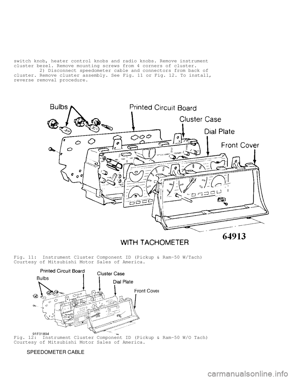
switch knob, heater control knobs and radio knobs. Remove instrument
cluster bezel. Remove mounting screws from 4 corners of cluster.
2) Disconnect speedometer cable and connectors from back of
cluster. Remove cluster assembly. See Fig. 11 or Fig. 12. To install,
reverse removal procedure.
Fig. 11: Instrument Cluster Component ID (Pickup & Ram-50 W/Tach)
Courtesy of Mitsubishi Motor Sales of America.
Fig. 12: Instrument Cluster Component ID (Pickup & Ram-50 W/O Tach)
Courtesy of Mitsubishi Motor Sales of America.
SPEEDOMETER CABLE
Page 674 of 1333

1 - 20 Amp (Yellow)
Hazard Light, Dome Light, Clock
2 - 10 Amp (Red)
Taillights
3 - 10 Amp (Red)
Turn Signal Lights
4 - 10 Amp (Red)
Back-Up Lights, Gauges
5 - 15 Amp (Light Blue)
Defogger
6 - 20 Amp (Yellow)
Heater
7 - 15 Amp (Light Blue)
Stoplights
8 - 15 Amp (Light Blue)
Horn, Wiper, Washer
9 - 10 Amp (Red)
Rear Wiper, Rear Washer
10 - 15 Amp (Light Blue)
Cigarette Lighter, Radio
FUSE PANEL IDENTIFICATION (1992-96)
Fig. 9: Fuse Panel Identification (1992-96)
Courtesy of Mitsubishi Motor Sales of America, Inc.
Fuse & Circuit Breaker Identification
Page 675 of 1333

1 - 20 Amp
Not Used
2 - Not Used
10 Amp (1994-96)
ELC-4 A/T Control Module, Cruise Control Unit
3 - 10 Amp
Blower Motor Relay, Headlight Washer Relay, Defogger Relay,
Car Telephone (1992-93)
4 - 10 Amp
Radio Clock, Accessory Socket Relay,
Cruise Control Unit (1994-96), Data Link Connector (1994-96)\
5 - 15 Amp
Remote Controlled Mirror, Cigarette Lighter
Accessory Socket Relay (1992-93)
6 - 15 Amp
Door Lock Relay, Door Lock Control Unit (1994-96)
7 - 10 Amp
Overdrive Relay, Variable Shock Absorber Control Unit,
4WD Indicator Control Unit, ABS Power Relay (1992-93),
ABS Control Unit (1994-96), Combination Meter (1994-96)
8 - 10 Amp
Power Window Relay
9 - 15 Amp
Wiper, Washer, Sunroof
10 - 10 Amp
Horn, Cruise Control Unit (1992-93)
11 - 10 Amp
Combination Meter, Multi-meter, Motor Antenna Control Unit,
Buzzer Assembly
12 - 15 Amp
Turn Signal Light, Hazard Light, SRS Diagnosis Unit
13 - 10 Amp
Not Used
14 - 15 Amp
Accessory Socket
15 - Not Used
16 - 25 Amp
Blower Motor
17 - 15 Amp
Stoplight
18 - 10 Amp
Back-up Light, Rear Differential Lock Control Unit
19 - 10 Amp
Engine Control Module, Dome Light, Reading Light,
Cargo Light, Combination Meter, Clock, Door Lock Relay,
Cruise Control Unit, Car Telephone (1992-93)
ELC-4 A/T Control Module (1994-96), Ignition Key Illumination\
Light Timer (1994-96)
Page 697 of 1333

WARNING: Avoid breathing R-134a refrigerant and PAG lubricant vapors,
exposure may irritate eyes, nose and throat. To remove
R-134a from system use R-134a recycling equipment that meets
SAE J2210 specifications. If accidental system discharge
occurs, ventilate work area before resuming service.
ANTI-LOCK BRAKE SYSTEM
The anti-lock brake system contains electronic equipment that
can be susceptible to interference caused by improperly installed or
high output radio transmitting equipment. Since this interference
could cause the possible loss of the anti-lock braking capability,
such equipment should be installed by qualified professionals.
On models equipped with anti-lock brake systems, ALWAYS
observe the following cautions:
* DO NOT attempt to bleed hydraulic system without first
referring to the appropriate ANTI-LOCK BRAKE SYSTEM article
in the BRAKES Section.
* DO NOT mix tire sizes. As long as tires remain close to the
original diameter, increasing the width is acceptable.
Rolling diameter must be identical for all 4 tires. Some
manufacturers recommend tires of the same brand, style and
type. Failure to follow this precaution may cause inaccurate
wheel speed readings.
* Use ONLY recommended brake fluids. DO NOT use silicone brake
fluids in an ABS-equipped vehicle.
REPLACING BLOWN FUSES
Before replacing a blown fuse, remove ignition key, turn off
all lights and accessories to avoid damaging the electrical system. Be
sure to use fuse with the correct indicated amperage rating. The use
of an incorrect amperage rating fuse may result in a dangerous
electrical system overload.
BATTERY WARNING
WARNING: When battery is disconnected, vehicles equipped with
computers may lose memory data. When battery power is
restored, driveability problems may exist on some vehicles.
These vehicles may require a relearn procedure. See
appropriate COMPUTER RELEARN PROCEDURES article in the
GENERAL INFORMATION section below.
BRAKE FLUID
For vehicles equipped with a traction control system, idle
engine while pouring brake fluid into reservoir.
CATALYTIC CONVERTER
Continued operation of vehicle with a severe malfunction
could cause converter to overheat, resulting in possible damage to
converter and vehicle.
ELECTROSTATIC DISCHARGE SENSITIVE (ESD) PARTS
WARNING: Many solid state electrical components can be damaged by
static electricity (ESD). Some will display a warning label,
but many will not. Discharge personal static electricity by
Page 835 of 1333

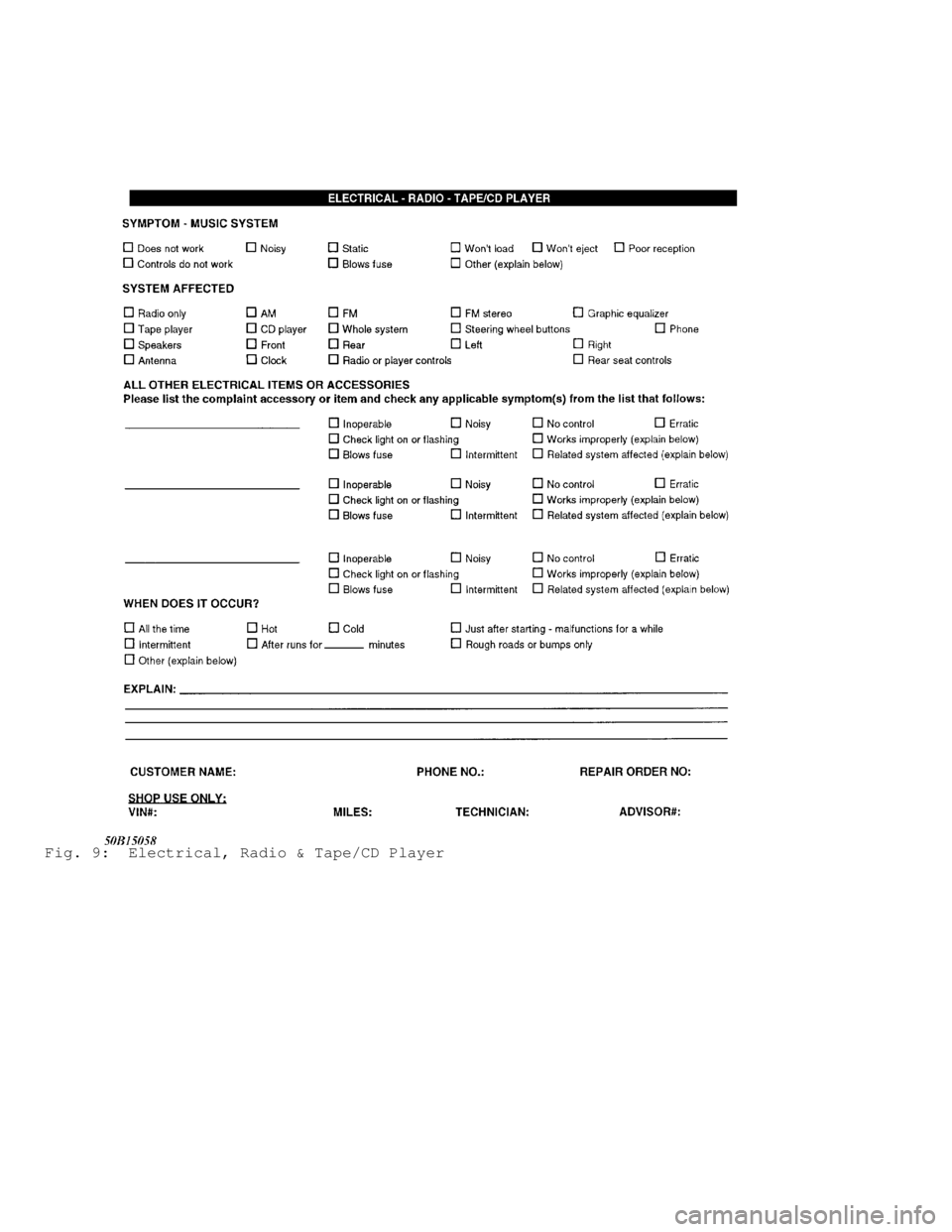
Fig. 9: Electrical, Radio & Tape/CD Player