Page 189 of 1216

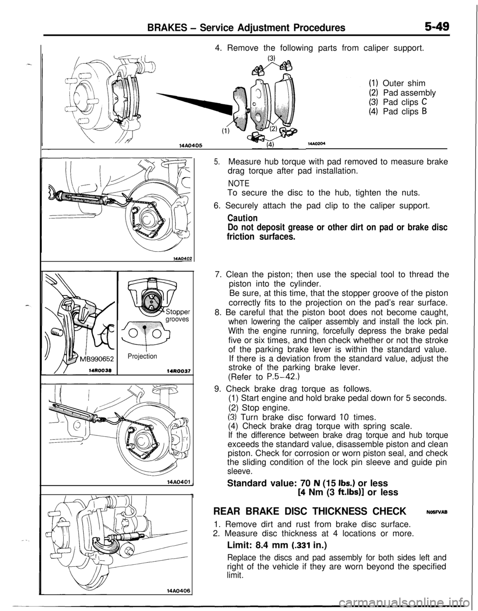
BRAKES - Service Adjustment Procedures5-494. Remove the following parts from caliper support.
14AO405
14AOs
grooves
Q
0 0
Projection
14R0037
14A0401
14AO406
MAO204Outer shim
Pad assembly
Pad clips
CPad clips
B
5.Measure hub torque with pad removed to measure brake
drag torque after pad installation.
NOTETo secure the disc to the hub, tighten the nuts.
6. Securely attach the pad clip to the caliper support.
Caution
Do not deposit grease or other dirt on pad or brake disc
friction surfaces.7. Clean the piston; then use the special tool to thread the
piston into the cylinder.
Be sure, at this time, that the stopper groove of the piston
correctly fits to the projection on the pad’s rear surface.
8. Be careful that the piston boot does not become caught,
when lowering the caliper assembly and install the lock pin.
With the engine running, forcefully depress the brake pedalfive or six times, and then check whether or not the stroke
of the parking brake lever is within the standard value.
If there is a deviation from the standard value, adjust the
stroke of the parking brake lever.
(Refer to
P.5-42.)9. Check brake drag torque as follows.
(1) Start engine and hold brake pedal down for 5 seconds.
(2) Stop engine.
(3) Turn brake disc forward 10 times.
(4) Check brake drag torque with spring scale.
If the difference between brake drag torque and hub torqueexceeds the standard value, disassemble piston and clean
piston. Check for corrosion or worn piston seal, and check
the sliding condition of the lock pin sleeve and guide pin
sleeve.Standard value: 70
N (15 Ibs.) or less
[4 Nm (3 ft.lbs)] or less
REAR BRAKE DISC THICKNESS CHECKNOSWAB
1. Remove dirt and rust from brake disc surface.
2. Measure disc thickness at 4 locations or more.
Limit: 8.4 mm
(.331 in.)
Replace the discs and pad assembly for both sides left andright of the vehicle if they are worn beyond the specified
limit.
Page 192 of 1216

5-52BRAKES - Service Adjustment Procedures
16LO312lOWOO
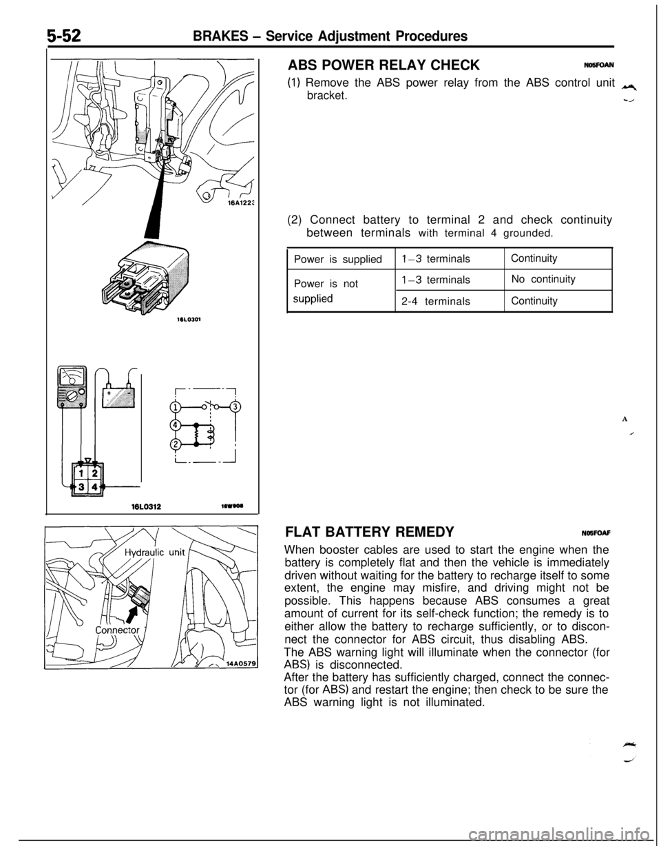
(1) Remove the ABS power relay from the ABS control unit q
bracket.-/ABS POWER RELAY CHECK
NO5FOAN(2) Connect battery to terminal 2 and check continuity
between terminals with terminal 4 grounded.
Power is supplied
Power is not
supplied
l-3 terminals
1-3 terminals
2-4 terminalsContinuity
No continuity
Continuity
A
IFLAT BATTERY REMEDYNOWOAF
When booster cables are used to start the engine when the
battery is completely flat and then the vehicle is immediately
driven without waiting for the battery to recharge itself to some
extent, the engine may misfire, and driving might not be
possible. This happens because ABS consumes a great
amount of current for its self-check function; the remedy is to
either allow the battery to recharge sufficiently, or to discon-
nect the connector for ABS circuit, thus disabling ABS.
The ABS warning light will illuminate when the connector (for
ABS) is disconnected.
After the battery has sufficiently charged, connect the connec-
tor (for
ABS) and restart the engine; then check to be sure the
ABS warning light is not illuminated.
Page 201 of 1216

BRAKES - Brake Booster5-61Vacuum hose
MAO394
14uoo50
14Y626Vacuum hose
mm (in.)
14A0395
SERVICE POINTS OF REMOVALNow9Al
6. REMOVAL OF VACUUM HOSE WITH CHECK VALVE
NOTE
Since the check valve is fit to the vacuum hose, replace thecheck valve as an assembly unit together with the vacuum
hose if the check valve is defective.
SERVICE POINTS OF INSTALLATIONNOWDAV
10. APPLICATION OF GREASE TO CLEVIS PIN/g. WASHERAfter applying the specified grease to the
clevis pin and
washer, insert the clevis pin and bend the cotter pin tightly.
Grease: MOPAR Multi-mileage Lubricant
Part No. 2525035 or equivalent
7. APPLICATION OF SEALANT TO
FITTINGWhen installing the vacuum hose fitting, apply semi-drying
sealant to its threaded portion.
6. INSTALLATION OF VACUUM HOSE WITH CHECK
VALVE(1) Attach the vacuum hose so that it may be inserted to a
dimension illustrated.
Caution
Prevent interference between the check valve and
brake booster.(2) The vacuum hose at the engine should be securely
connected until it contacts the hexagonal edge of the
fitting, and then should be secured by the hose clip.
Page 206 of 1216
5,966BRAKES - Front Disc Brake
14A04001410399
SERVICE POINTS OF INSTALLATIONNO5LDAG
2. INSTALLATION OF FRONT BRAKE ASSEMBLY(1) Measure hub torque with pad removed to measure
brake drag torque after pad installation.
NOTETighten the nuts in order to secure the disc to the hub.
(2) After installing the caliper support to the knuckle,
expand the piston, and then install the caliper body.
1. INSTALLATION OF BRAKE HOSEInstall brake hose without twisting or kinking.
Check brake drag torque as follows.
(1) Start engine and hold brake pedal down for 5 seconds.
(2) Stop engine.
(3) Turn brake disc forward 10 times.
(4) Check brake drag torque with spring scale.
If the difference between brake drag torque and hub torque
exceeds the standard value, disassemble piston and cleanthe piston. Check for corrosion or worn piston seal.
Standard value: 70
N (15 Ibs.) or less[4 Nm (3
ft.lbs.)J or less
Page 216 of 1216
5-76BRAKES - Rear Disc Brake
hide pin end
Caliper supportLock pin end
6. APPLICATION OF GREASE TO GUIDE PIN BOOT/
5. LOCK PIN BOOT/4. LOCK PIN SLEEVEApply the specified grease to the following points:
(1) Guide pin boot inner surface (lip)
(2) Lock pin boot inner surface (lip)
(3) Lock pin sleeve (not on threads)
Specified grease: Repair kit grease (orange)
After assembling the rear disc brake assembly, install to thebody, and then make the adjustment of the parking brake
lever as described below.
(1) Free the parking brake cable.
(2) With the engine running, firmly depress the brake pedalfive or six times.
(3) Check whether or not the stroke of the parking brake
lever is within the standard value.
Standard value: 5-7 notches
(4) If there is a deviation from the standard value, adjust
the stroke of the parking brake lever.
(Refer to
P.5-42.)
Page 231 of 1216

6-I
CLUTCH
CONTENTS
CLUTCH CONTROL. . . . . . . . . . . . . . . . . . . . . . . . . . . . . . . . . . . . . . . . .9SPECIFICATIONS. . . . . . . . . . . . . . . . . . ..m........................2
GeneralSpecifications..................................2CLUTCH COVER AND DISC..........................16Lubricants......................................................3
CLUTCH MASTER CYLINDER........................11Service Specifications...................................2Torque Specifications
...................................3
CLUTCH PEDAL..............................................7
TROUBLESHOOTING. . . . . . . . . . . . . . . . . . . . . . . ..*............4
CLUTCHRELEASE CYLINDER . . . . . . . ..a.............13Clutch chatters
SERVICE ADJUSTMENT PROCEDURES . . . . . . .5Clutch noise
Bleeding. . . . . . . . . . . . . . . . . . . . . . . . . . . . . . . . . . . . . . . . . . . . . . . . . . . . . . . .6Clutch pedal feels “heavy”
Clutch Pedal Inspection and Adjustment . . . .
5Clutch slips
SPECIAL TOOL,.,#mmm,.*......B......................*........3Gear shift malfunctionCAUTIONWhen
servicing clutch assemblies or com-
ponents for vehicles with 1.8L engine, doNOT
create dust by sanding or by cleaning
clutch parts with a dry brush or with
compressed air. (A water dampened cloth
should be used). The clutch disc contains
“Asbestos Fibers” which can become air-
borne if dust is created during serviceoperations. Breathing dust containing
“Asbestos Fibers”may cause seriousbodily
harm.
Page 232 of 1216

6-2CLUTCH - SDecifications
SPECIFICATIONS
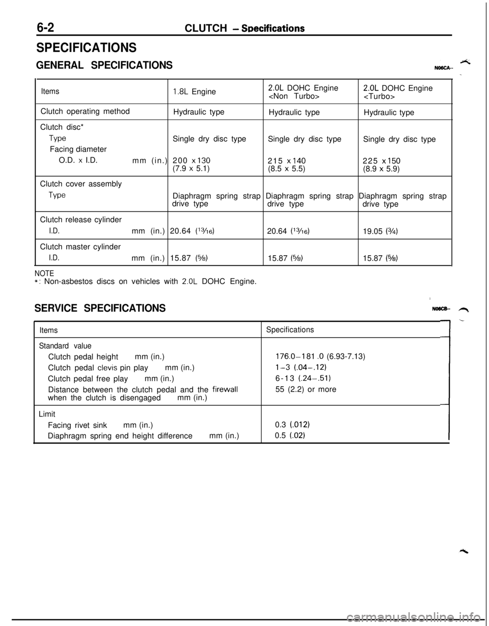
GENERAL SPECIFICATIONS
Items1.8L Engine2.0L DOHC Engine
2.0L DOHC Engine
Clutch operating method
Hydraulic type
Hydraulic type
Hydraulic type
Clutch disc*
TypeSingle dry disc type
Single dry disc type
Single dry disc type
Facing diameter
O.D.
x I.D.
mm (in.) 200 x 130215 x 140225 x 150(7.9 x 5.1)
(8.5 x 5.5)
(8.9 x 5.9)
Clutch cover assembly
TypeDiaphragm spring strap Diaphragm spring strap Diaphragm spring strap
drive type
drive type
drive type
Clutch release cylinder
I.D.mm (in.) 20.64 (13/16)20.64 (13/6)19.05 (3h)Clutch master cylinder
I.D.mm (in.) 15.87 (%)15.87 (%)15.87 (543)
NOTE*: Non-asbestos discs on vehicles with 2.0L DOHC Engine.
SERVICE SPECIFICATIONS
Items
Standard valueClutch pedal heightmm (in.)
Clutch pedal
clevis pin playmm (in.)
Clutch pedal free playmm (in.)
Distance between the clutch pedal and the firewall
when the clutch is disengagedmm (in.)
Limit
Facing rivet sinkmm (in.)
Diaphragm spring end height differencemm (in.)
NO6lX- .H,
Specifications
176.0-I 81 .O (6.93-7.13)
l-3 (.04-.12)6-13 (.24-.51)
55 (2.2) or more
0.3 (012)
0.5
(.02)L-
Page 249 of 1216

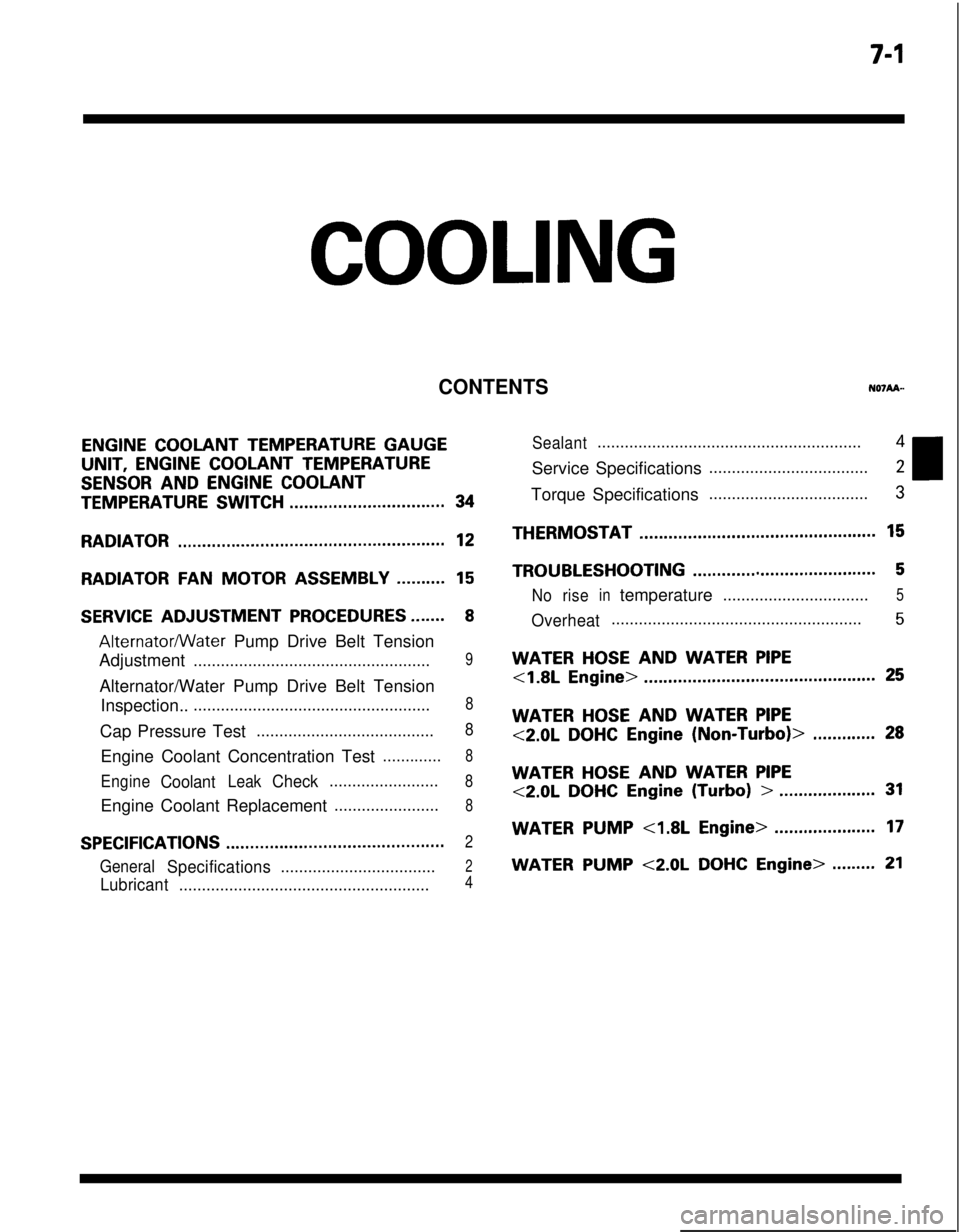
7-l
COOLING
CONTENTS
ENGINE COOLANT TEMPERATURE GAUGEUNIT,
ENGINE COOLANT TEMPERATURE
SENSOR AND ENGINE COOLANT
TEMPERATURE SWITCH................................34
RADIATOR.......................................................12
RADIATORFANMOTOR ASSEMBLY..........15
SERVICE ADJUSTMENT PROCEDURES.......8
Alternatormater Pump Drive Belt Tension
Adjustment
....................................................9Alternator/Water Pump Drive Belt Tension
Inspection..
....................................................8Cap Pressure Test
.......................................8Engine Coolant Concentration Test
.............8
EngineCoolantLeakCheck........................8Engine Coolant Replacement
.......................8
SPECIFICATIONS.............................................2
GeneralSpecifications..................................2
Lubricant.......................................................4
Sealant..........................................................4Service Specifications
...................................2Torque Specifications
...................................3THERMOSTAT
.................................................15
TROUBLESHOOTING......................................5
Noriseintemperature................................5
Overheat.......................................................5
WATER HOSE AND WATER PIPE
<1.8L Engine>................................................25
WATER HOSE AND WATER PIPE
<2.0LDOHCEngine(Non-Turbo)>.............28
WATER HOSE AND WATER PIPE
<2.0LDOHCEngine(Turbo)>....................31
WATERPUMP<1.8LEngine>.....................17
WATER PUMP <2.0L DOHC Engine>.........21