Page 677 of 1216

STEERING - Power Steering Gear Box
lS1017S
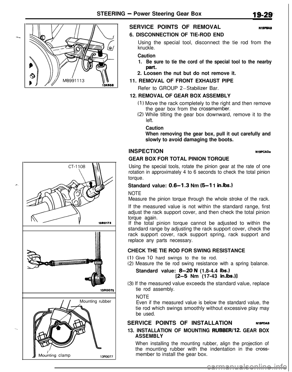
I /Mounting rubber
IIMdting clamp13Roo77
5SERVICE POINTS OF REMOVAL
NIBPNAB6. DISCONNECTION OF TIE-ROD END
Using the special tool, disconnect the tie rod from the
knuckle.
Caution
1.Be sure to tie the cord of the special tool to the nearby
part.2. Loosen the nut but do not remove it.
11. REMOVAL OF FRONT EXHAUST PIPE
Refer to GROUP
2-Stabilizer Bar.
12. REMOVAL OF GEAR BOX ASSEMBLY
(I 1 Move the rack completely to the right and then remove
the gear box from the
crossmember.
(2) While tilting the gear box downward, remove it to the
left.
Caution
When removing the gear box, pull it out carefully andslowly to avoid damaging the boots.
INSPECTION
NlSPCADaGEAR BOX FOR TOTAL PINION TORQUE
Using the special tools, rotate the pinion gear at the rate of one
rotation in approximately 4 to 6 seconds to check the total pinion
torque.Standard value:
0.6-l .3 Nm (5-l 1 in.lbs.1
NOTE
Measure the pinion torque through the whole stroke of the rack.If the measured value is not within the standard range, first
adjust the rack support cover, and then check the total pinion
torque again.If the total pinion torque cannot be adjusted to within the
standard range by adjusting the rack support cover, check the
rack support cover, rack support spring, rack support and
replace any parts necessary.CHECK THE TIE ROD FOR SWING RESISTANCE
(1) Give 10 hard swings to the tie rod.I
(2) Measure the tie rod swing resistance with a spring balance.
’Standard value: 8-20 N (1.8-4.4 Ibs.)
12-5 Nm (17-43 in.lbs.)l
(3) If the measured value exceeds the standard value, replace
tie rod assembly.
NOTE
Even if the measured value is below the standard value, thetie rod which swings smoothly without excessive play may
be used.SERVICE POINTS OF INSTALLATION
Nl9PDA9
13. INSTALLATION OF MOUNTING RUBBER/lZ. GEAR BOX
ASSEMBLY
When installing the mounting rubber, align the projection ofthe mounting rubber with the indentation in the
cross-member to install the gear box.
Page 679 of 1216
STEERING - Power Steering Gear Box
13PO126SERVICE POINTS OF DISASSEMBLY
NISAK3. REMOVAL OF DUST COVER.4
IRemove the dust cover from the tie rod end.
5. REMOVAL OF BELLOWS BAND
Using a screwdriver or similar tool, loosen and then removethe boot retaining band.
7. REMOVAL OF TAB WASHER
Unstake the tab washer which fixes the tie rod and rack with
a chisel.11. REMOVAL OF END PLUG
Disconnect end plug caulking and remove end plug.
14. REMOVAL OF RACK SUPPORT COVER
Using the special tool, remove the rack support cover fromthe gear box.
Page 681 of 1216

STEERING - Power Steering Gear Box4 $143
13130549
13Ro581
Pipe
13RO218
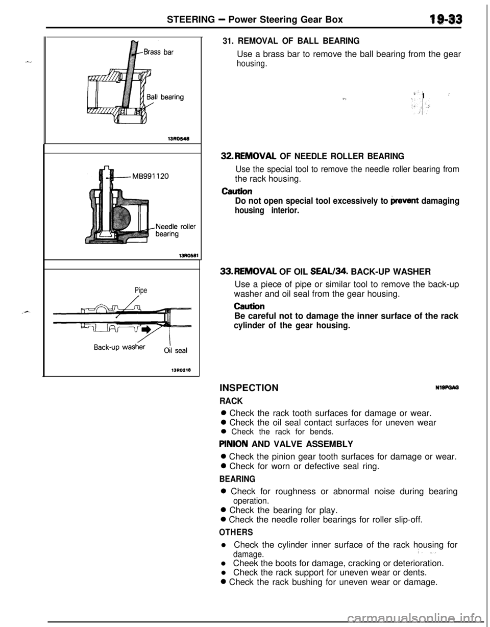
31. REMOVAL OF BALL BEARINGUse a brass bar to remove the ball bearing from the gear
housing.
-)-’9,I :
>.,I:32.REMOVAL
OF NEEDLE ROLLER BEARING
Use the special tool to remove the needle roller bearing fromthe rack housing.
Caution
Do not open special tool excessively to
prevent damaging
housing interior.33.REMOVAL OF OIL SEAL/34. BACK-UP WASHER
Use a piece of pipe or similar tool to remove the back-up
washer and oil seal from the gear housing.
CautionBe careful not to damage the inner surface of the rack
cylinder of the gear housing.INSPECTION
RACK
NlSPOIO0 Check the rack tooth surfaces for damage or wear.0 Check the oil seal contact surfaces for uneven wear
0 Check the rack for bends.
PlNlON AND VALVE ASSEMBLY0 Check the pinion gear tooth surfaces for damage or wear.0 Check for worn or defective seal ring.
BEARING0 Check for roughness or abnormal noise during bearing
operation.0 Check the bearing for play.0 Check the needle roller bearings for roller slip-off.
OTHERSl Check the cylinder inner surface of the rack housing for
damage.i. ,..l Cheek the boots for damage, cracking or deterioration.
l Check the rack support for uneven wear or dents.0 Check the rack bushing for uneven wear or damage.
Page 710 of 1216
21-16MANUAL TRANSAXLE - Transaxle Control
INSPECTIONN21JcAD
ICBA0160 1Incorrect
5I,I
-ri
IIIncorrect
1,-I I,,1 :
Sele’ctcableFlange side
yof the resin LbushingLever
&OSAOl72l Check the select
cable for funct,ion and for damage.
l Check the shift cable for function and for damage.
l Check the boot for damage.
l Check each bushing for wear or abrasion, sticking,
impeded action, and damage.
l Check the spring for deteriorated strength.
SERVICE POINTS OF INSTALLATION
NZlJDAK17. INSTALLATION OF SELECT CABLE
(1) Move the transaxle shift lever to the neutral position.
NOTEThe select lever will be set to the neutral position when
the transaxle shift lever is moved to the neutral
position.(2) Move lever
(6) to the neutral position.
(3) Adjust, by using the adjuster, so that the end of the
select cable is positioned as shown in the illustration
relative to lever
(B).
k,I.,,(4) The flange side of the resin bushing at the select cable
end should be at the lever
(B) end surface.
A.
Page 760 of 1216
21-66MANUAL TRANSAXLE - Clutch Housing Assembly
CLUTCH HOUSING ASSEMBLYNZlMPAL
DISASSEMBLY AND REASSEMBLY
2=
-,_
1
L--15-22 Nm
11-15 ftlbs.
20-27 Nm15-19 ft.lbs.
Disassembly steps
1.Bolt2. Select lever assembly
3. Select lever shoe
4. Interlock place bolt
5.Gasket+e l *6. Lock pinj\l * l *7. Spring pin
8. Neutral return spring
9.Stopper body10.Control finger11.Interlock plate
12. Neutral return spring assembly
13.Control shaft14. Control shaft boot
l 415.Oil seal
2100019
l * 16. Needle bearing
l a 17. Needle bearing;EJ. Fil;tch housing
20: Return spring
21. Stopper plate
22. Spring pin
NOTE(1) Reverse the disassembl procedures to reassemble.(2)~~ : Refer to “Service ornts of Disassembly”.6.(3)l + : Refer to “Service Points of Reassembly”.(4) q : Non-reusable parts
Page 815 of 1216
MANUAL TRANSAXLE - Clutch Housing Assembly21-121
CLUTCH HOUSING ASSEMBLY
-- DISASSEMBLY AND REASSEMBLY
NZlMPAH
-20-27 Nm
15-
19 ft.lbs.
15-22 Nm15 ft.lbs.18'
Disassembly steps
I, Bolt
2. Select lever assembly
3. Select lever shoe4. Interlock plate bolt
5.Gasket+* WC 6. Lock pinl * l *7. Spring pin
8. Neutral return spring
9.Stopper body10.Control finger11,Interlock plate
12. Neutral return spring assembly
13.Control shaft14. Control shaft boot
2210128
l * 15. Oil seal*I) l * 16. Needle bearing
a* l + 17. Needle bearing18. Clutch housing
19. Pin
20. Return spring21. Stopper plate
22. Spring pin
NOTE(1)Reverse the disassembly procedures to reassemble.(2)l +: Refer to “Service Points of Disassembly”.(3)l C: Refer to “Service Points of Reassembly”.(4) a: Non-reusable parts.
Page 1128 of 1216