Page 308 of 1216

9-24ENGINE - Service Adjustment Procedures
ENGINE 4.8L Engine>
SERVICE ADJUSTMENT PROCEDURES -
CHECKING COMPRESSION PRESSURENOSFFAI
(1) Before checking compression, ensure that engine oil, the
starter motor, and battery are all in good condition.
(2) Start the engine and wait until engine coolant temperature
has risen to
85-95°C (185-205°F).
(3) Stop the engine and pull the spark plug cables.
(4) Remove the spark plugs.
(5) Crank the engine to remove any foreign objects in the
cylinders.Caution
Cover the spark plug holes with shop towel, etc., in
order to keep expelled foreign objects from flying out,
and keep away from the holes. When measuring
compression with water, oil, or fuel having entered the
cylinder through a crack, etc., these will come flying
out of the spark plug hole hot and fast, so be sure to
take the proper precautions.
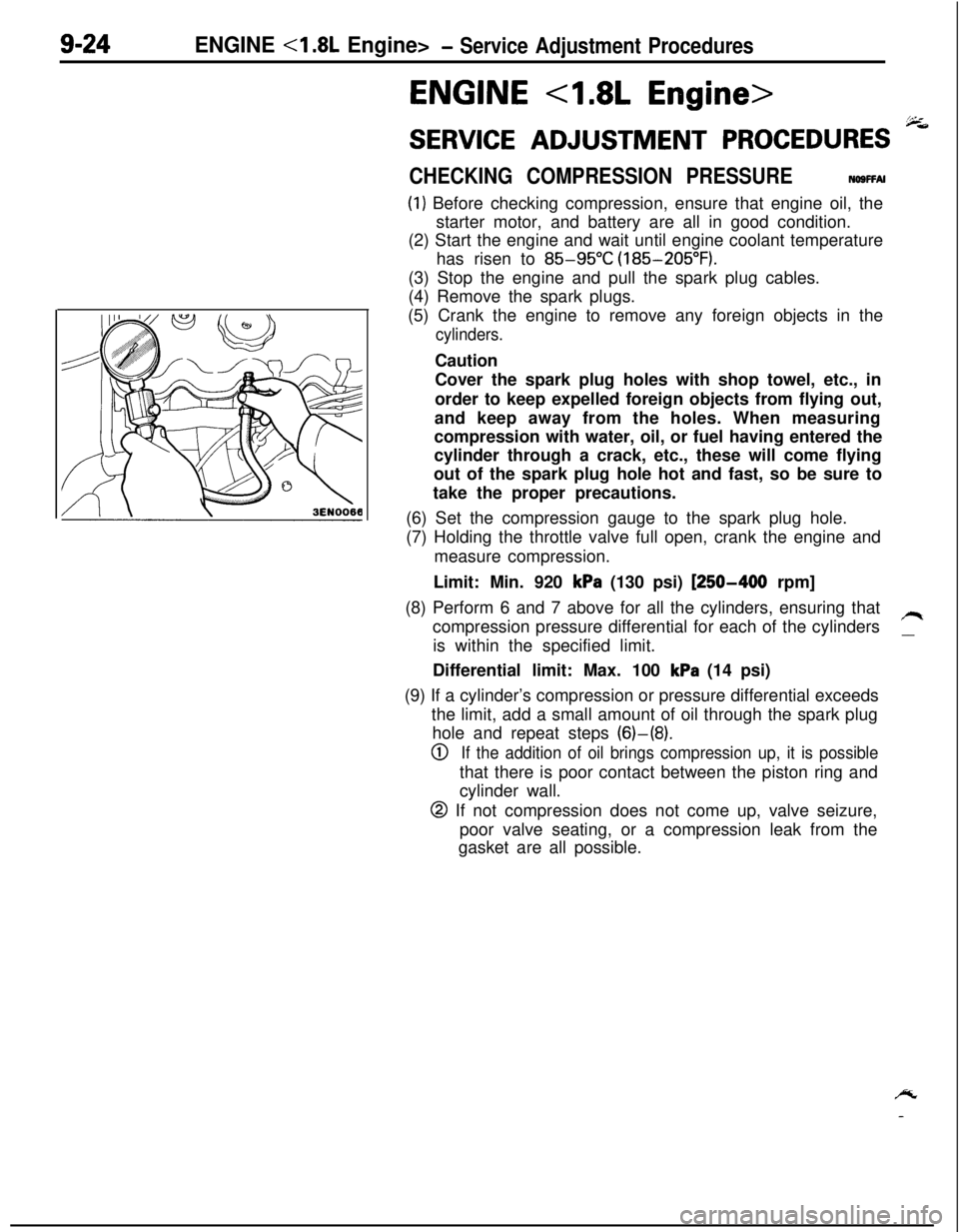
(6) Set the compression gauge to the spark plug hole.
(7) Holding the throttle valve full open, crank the engine and
measure compression.
Limit: Min. 920
kPa (130 psi) [250-400 rpm]
(8) Perform 6 and 7 above for all the cylinders, ensuring that
compression pressure differential for each of the cylinders
/Iis within the specified limit.
__Differential limit: Max. 100
kPa (14 psi)
(9) If a cylinder’s compression or pressure differential exceeds
the limit, add a small amount of oil through the spark plug
hole and repeat steps (6)-(8).
0If the addition of oil brings compression up, it is possiblethat there is poor contact between the piston ring and
cylinder wall.
@ If not compression does not come up, valve seizure,
poor valve seating, or a compression leak from the
gasket are all possible.
/y
-
Page 358 of 1216

9-74ENGINE <2.0L DOHC Engine>- Service Adjustment Procedures
ENGINE <2.0L DOHC Engine>
SERVICE ADJUSTMENT PROCEDURES pi
CHECKING COMPRESSION PRESSURENOSFFAH(1) Before checking compression, ensure that engine oil, the
starter motor, and battery are all in good condition.
(2) Start the engine and wait until engine coolant temperature
has risen to
85-95°C (185-205°F).
(3) Stop the engine and pull the spark plug cables.
(4) Remove the spark plugs.
(5) Crank the engine
to. remove any foreign objects in the
cylinders.
Caution
Cover the spark plug holes with shop towel, etc., in
order to keep expelled foreign objects from flying out,and keep away from the holes. When measuring
compression with water, oil, or fuel having entered the
cylinder through a crack, etc., these will come flying
out of the spark plug hole hot and fast, so be sure to
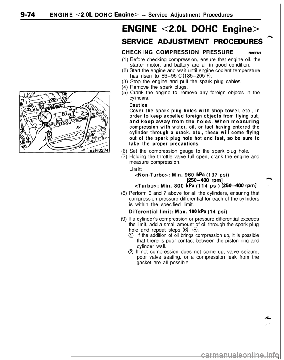
take the proper precautions.(6) Set the compression gauge to the spark plug hole.
(7) Holding the throttle valve full open, crank the engine and
measure compression.
Limit:
: Min. 960 kPa (137 psi)
[250-400 rpm]6: Min. 800
kPa (114 psi) [250-400 rpml-(8) Perform 6 and 7 above for all the cylinders, ensuring that
compression pressure differential for each of the cylinders
is within the specified limit.
Differential limit: Max. 100 kPa (14 psi)(9) If a cylinder’s compression or pressure differential exceeds
the limit, add a small amount of oil through the spark plug
hole and repeat steps (6)-(8).
@If the addition of oil brings compression up, it is possiblethat there is poor contact between the piston ring and
cylinder wall.
@ If not compression does not come up, valve seizure,
poor valve seating, or a compression leak from the
gasket are all possible.‘I
Page 598 of 1216

16-2PROPELLER SHAFT - Specifications
SPECIFICATIONS
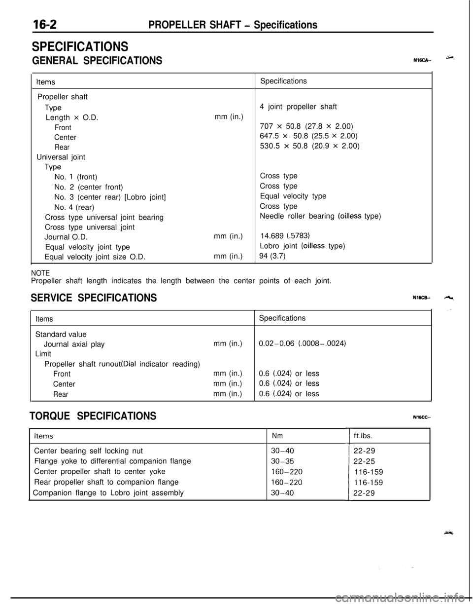
GENERAL SPECIFICATIONSNWCA--
ItemsPropeller shaft
TypeLength
x O.D.
Front
Center
RearUniversal joint
TypeSpecifications
4 joint propeller shaft
mm (in.)
707
x 50.8 (27.8 x 2.00)
647.5
x. 50.8 (25.5 x 2.00)
530.5
x 50.8 (20.9 x 2.00)
No.
1 (front)
No. 2 (center front)
No. 3 (center rear) [Lobro joint]
No. 4 (rear)
Cross type universal joint bearing
Cross type universal joint
Journal O.D.
Equal velocity joint type
Equal velocity joint size O.D.mm (in.)
mm (in.)Cross type
Cross type
Equal velocity type
Cross type
Needle roller bearing
(oilless type)
14.689
(.5783)Lobro joint
(oilless type)
94 (3.7)
NOTEPropeller shaft length indicates the length between the center points of each joint.
SERVICE SPECIFICATIONSNWCB-
ItemsSpecifications
Standard value
Journal axial playmm (in.)
0.02-0.06 (.0008-.0024)
Limit
Propeller shaft
runout(Dial indicator reading)
Frontmm (in.)
0.6 (.024) or less
Centermm (in.)0.6 (.024) or less
Rearmm (in.)0.6 (.024) or less
TORQUE SPECIFICATIONSNlBCC--
ItemsNmCenter bearing self locking nut
30-40Flange yoke to differential companion flange
30-35Center propeller shaft to center yoke
160-220Rear propeller shaft to companion flange
160-220Companion flange to Lobro joint assembly
30-40tft.lbs.
22-29
22-25
116-159
116-159
22-29
Page 600 of 1216

16-4PROPELLER SHAFT - Propeller Shaft
PROPELLER SHAFT
REMOVAL AND INSTALLATIONNlffiA--
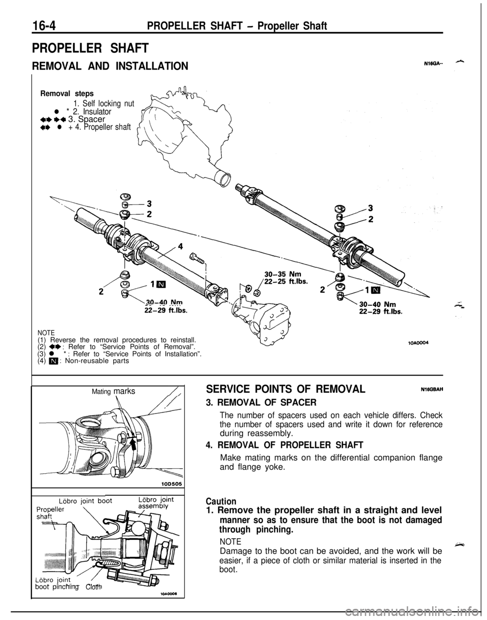
Removal steps
1. Self locking nut
l * 2. Insulator*I)+* 3. Spacer+e l + 4. Propeller shaft
- -. - . . .ii-29 ftlbs.
NOTE(1) Reverse the removal procedures to reinstall.
(2)
+* : Refer to “Service Points of Removal”.
(3) l * : Refer to “Service Points of Installation”.
(4) m : Non-reusable parts
lOAOOO4
Mating marks/,
lOD505
LBbro jointboot pinching
Cloth
SERVICE POINTS OF REMOVALNlEGBAH
3. REMOVAL OF SPACER
The number of spacers used on each vehicle differs. Check
the number of spacers used and write it down for referenceduring reassembly.
4. REMOVAL OF PROPELLER SHAFTMake mating marks on the differential companion flange
and flange yoke.
Caution1. Remove the propeller shaft in a straight and level
manner so as to ensure that the boot is not damaged
through pinching.
NOTEDamage to the boot can be avoided, and the work will be
easier, if a piece of cloth or similar material is inserted in the
boot.
Page 627 of 1216

REAR SUSPENSION - SpecificationsT7-97
TORQUE SPECIFICATIONS. ‘2 +’ iiNl?GGbItems
Rear suspension assembly
Center exhaust pipe to main muffler installation bolt
Hook installation bolt
Hanger installation bolt
Center exhaust pipe to front exhaust pipe installation nut
Rear shock absorber installation nut
Differential carrier to differential support member
Differential support member to body
Brake tube bracket to rear shock absorber
Differential carrier to propeller shaft
Crossmember bracket to body
Crossmember bracket to crossmember
Rear brake assembly installation bolt
Rear speed sensor installation bolt
Jpper and lower arm
Upper arm to crossmember
Upper arm to knuckle
Lower arm to crossmember
Lower arm to knuckle
[railing arm
Companion flange to rear axle shaft
Companion flange to drive shaft
Trailing arm to crossmember
Upper arm to knuckle
Lower arm to knuckle
Rear shock absorber (lower)
Rear brake assembly installation bolt
Rear speed sensor installation bolt
Ghock absorber assembly
Shock absorber installation nut
Shock absorber installation bolt
Brake tube bracket to rear shock absorber
Piston rod tightening nut
stabilizer bar
Differential support member to body
Crossmember bracket to crossmember
Crossmember bracket to body
Stabilizer link to stabilizer bar
Nmft.lbs.
40-5029-36
IO-157-ii
IO-157-11
30-4022-29
40-5029-36
80-10058-72
110-13080-9417-26
12-19
30-3522-25
70-8551-61
110-13080-94
50-6036-43
9-14
7-10
140-160101-116
60-7243-52
90-I 1065-80
60-7243-52
160-220116-159
55-65
40-47
140-160101-116
60-7243-52
60-7243-52
90-I 1065-80
50-6036-43
9-14
7-10
40-5029-36
90-l 1065-8017-2612-19
20-2514-18
110-13080-94
110-13080-94
70-8551-61
35-4525-33
I'-'.
LUBRICANTNl’ICD-
ItemsSpecified lubricant
Lip and inside of the dust cover
(upper and lower arm, stabilizer link)MOPAR Multi-mileage Lubricant Part No. 2525035 or
equivalent
Page 632 of 1216
17-22REAR SUSPENSION - Rear Suspension Assembly
40-50 Nm
129-36 ft.lbs./
80-100 Nm
58-72 fiq T
i) 30-35 Nm,22-25 ftlbs.-- -- .-._--.I
17-26 Nm
t
12-19 ft.lbs.\
\
llO-i30 Nm80-94 ft.lbs.
70-85’ Nm51-61ftlbs.
I50-60Nm
36-43 ft.lbs.
70-85Nm51-61ft.lbs.80-94ftlbs.
12AO641Removal steps
+*9. Self locking nut
10. Differential support member
11. Crossmember bracket
4*12. Parking brake cable and rear speed sensorinstallation bolt
13. Cable band
4*14. Rear speed sensor connector
with
ABS15. O-ring16. Rear suspension assembly
NOTE(1) Reverse the removal procedures to reinstall.
(2)
+e : Refer to “Service Points of Removal”.
(3) l : Refer to “Service Points of Installation”.
(4) a : Non-reusable parts
Page 633 of 1216

REAR SUSPENSION - Rear Suspension ~Assembly
14AO520
12AOlOQ
SERVICE POINTS OF REMOVALN17GQAOa4. REMOVAL OF CALIPER ASSEMBLY
(1) Remove the lock pin, rotate the calipei
&&e-@blyupward, then remove the caliper assembly and secure
it with wire, etc.
Caution
The lock pin has a special grease appl‘ied tq it, so besure not to wipe it off, and ensure that the lock pin
stays clean.
(2) After removing the caliper assembly,
.cover the guide
pin with a cloth, etc.
8. REMOVAL OF PROPELLER SHAFT INSTALLATION
BOLT AND NUT
Place mating marks on the differential carrier companion
flange and the propeller shaft flange yoke.
NOTEThe mating marks should be used as a reference for
re-installation.9. REMOVAL OF SELF LOCKING NUT
(1) Before removing the self’ locking nuts, support the
differential case with a transaxle jack.
(2) Remove the self locking nuts.
12. REMOVAL OF PARKING BRAKE CABLE AND REAR
SPEED SENSOR INSTALLATION BOLT
(1) Lower the transaxle jack slightly.
(2) Remove the parking brake cable installation bolts.
NOTEThe task may be made easier by increasing the gap
between the body and the
crossmember.
Page 634 of 1216

17-24REAR SUSPENSION - Rear Suspension Assembly
1
II
brakeA022116. REMOVAL OF REAR SUSPENSION ASSEMBLY
(1) Supporting the rear suspension assembly with a trans-
mission jack, move it toward the rear (in the direction of
wtthe fuel tank).
c1(2) Gradually lower the transmission jack, avoiding contact
with the stabilizer bar and the propeller shaft.
Caution
1. Ensure that the propeller shaft does not bend
greatly.
2.Ensure that the liibro joint does not receive any
shock.
NOTEThe lowering of the rear suspension assembly from the
transmission jack requires three individuals due to the
amount of weight being handled (one on the differen-
tial, and one on either side of the lower arm).
(3) In order to protect the rear suspension assembly dust
shield, support the lower arm ball joint with a wooden
block.
INSPECTIONNl7GCAMl Check crossmember for cracks or other damage.
SERVICE POINTS OF INSTALLATIONN17GOAR -
8.INSTALLATION OF PROPELLER SHAFT INSTALLATIONBOLT AND NUT
Install the propeller shaft to the differential carrier, ensuringthat the mating marks are aligned.
3. INSTALLATION OF PARKING BRAKE CABLE END
NOTE
Connecting a parking brake cable end to parking brake lever
and prying up the parking brake lever, the installation of theother cable end will be easy.
’ice,