Page 509 of 1216

FUEL SYSTEM - Service Adjustment Procedures <2.0L Engine>14-55
(18)Connect the high-pressure fuel hose,,to the delivery pipe
and tighten the screws to the specified torque.
(19)Check for fuel leaks.
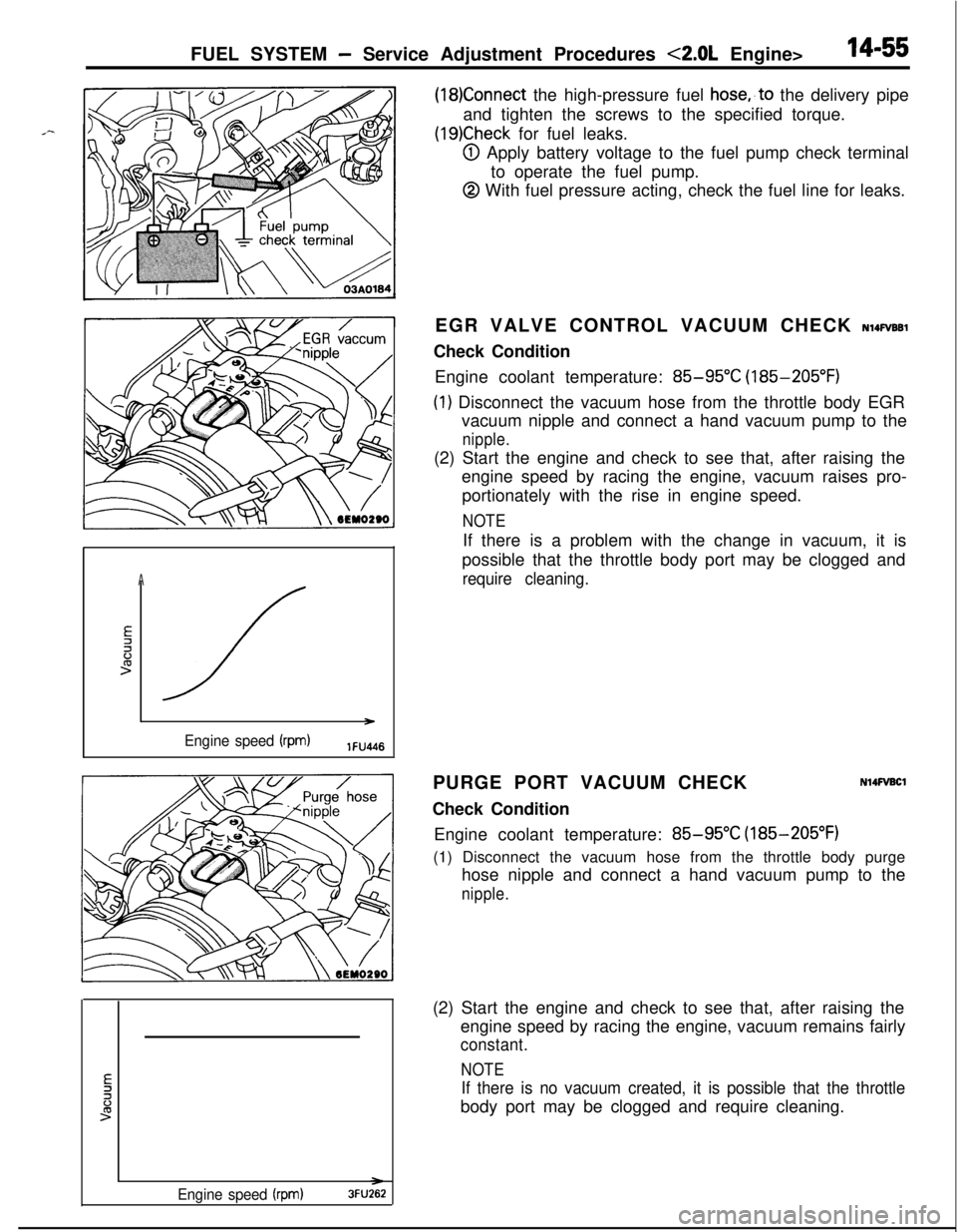
@I Apply battery voltage to the fuel pump check terminal
to operate the fuel pump.
@ With fuel pressure acting, check the fuel line for leaks.
A
E2li:>
/ )
Engine speed (rpm)lFU4l6EGR VALVE CONTROL VACUUM CHECK
NlQFVBBlCheck Condition
Engine coolant temperature:
85-95°C (185-205°F)
(1) Disconnect the vacuum hose from the throttle body EGR
vacuum nipple and connect a hand vacuum pump to the
nipple.(2) Start the engine and check to see that, after raising the
engine speed by racing the engine, vacuum raises pro-
portionately with the rise in engine speed.
NOTEIf there is a problem with the change in vacuum, it is
possible that the throttle body port may be clogged and
require cleaning.PURGE PORT VACUUM CHECK
Check Condition
N14FVBClEngine coolant temperature:
85-95°C (185-205°F)
(1) Disconnect the vacuum hose from the throttle body purge
hose nipple and connect a hand vacuum pump to the
nipple.
Engine speed (rpm)3FU262(2) Start the engine and check to see that, after raising the
engine speed by racing the engine, vacuum remains fairly
constant.
NOTE
If there is no vacuum created, it is possible that the throttlebody port may be clogged and require cleaning.
Page 512 of 1216

14-58FUEL SYSTEM -MPI System Inspection <1.8L Engine>
MALFUNCTION INDICATOR LIGHTNWQAB
Among the self-diagnosis items, a malfunction indicator light
comes on to notify the driver of the emission control items
when an irregularity is detected.
However, when an irregular signal returns to
notmal ‘and the
engine control unit judges that it has returned to normal, the
malfunction indicator light goes out.
Moreover, when the ignition switch is turned off, the light goes
out. Even if the ignition switch is turned on again, the light doesnot come on until the irregularity is detected.
Here, immediately after the ignition switch is turn on, the
malfunction indicator light is lit for 5 seconds to indicate that
the malfunction indicator light operates normally.
Items indicated by the lightening malfunction light
Engine control unit
Oxygen sensor
Air-flow sensor
Intake air temperature sensor
Throttle position sensor
Motor position sensor
Engine coolant temperature sensor
Crank angle sensor
No. 1 cylinder TDC sensor
Barometric pressure sensor
Ignition timing adjustment signal
Injector
Fuel pump
EGR system Caution
The malfunction indicator light lights up when the ignition
timing adjustment terminal is short-circuited
,‘t’o ground.
Consequently, it lights up ,when the ignition timing
adjustment is grounded when adjusting ignition timing,
but in this case there is no abnormality.
MALFUNCTION INDICATOR LIGHT INSPECTlON
When turning on the ignition switch, check that the light comes
on.
NOTElf the light does not come on, check the harness and light for
breakage.SELF-DIAGNOSIS
Nl4PMFaThe engine control unit monitors the input/output signals
(some signals at all times and the others under specified
conditions) of the engine control unit.
Page 515 of 1216

FUEL SYSTEM - MPI System Inspection <1.8L Engine>
outputDiagnosis code
referenceDiagnosis itemCheck item (Remedy)
orderOutput signal patternNo.Memory
7Engine coolantRetainedl Harness and connectortemperature sensor
:-rlrLn- 2’
l Engine coolant temper-
ature sensor
12A0107
8Crank angle sensor
:nn 22
Retainedl Harness and connector
(If harness and connector
are normal, replacedistributor assembly.)
12A0107
9No. 1 cylinder top
dead center sensorH
Lnn 23
Retainedl Harness and connector
(If harness and connector
are normal, replacedistributor assembly.)
12A0107
10Vehicle speed sensor24Retainedl Harness and connector
(reed switch)H
Lu 1 nnJln
l Vehicle speed sensor
(reed switch)
12A0107
11Barometric pressure25Retainedl Harness and connector
sensorH
u I nl-uvln
(If harness and connector
are normal, replace
Lbarometric pressure
12A0107sensor assembly.)
12Ignition timing adjust-36-l Harness and connectorment signalH
LUUI nluvuuL
12R0468
13Injector
:m 41
Retainedl Harness and connector0 Injector coil resistance
12A0105
14Fuel pump42Retainedl Harness and connectorH0 Control relay
LUUUI nn
12A0105
15EGR 43Retainedl Harness and connectorl EGR temperature sensor
H
u u u u-inn
l EGRvalvel EGR valve control sole-Lnoid valve
12A0105l EGR valve control vacuurr
16Normal state---H
Ln
12A0104
NOTEReplace the engine control unit if a malfunction code is output although the inspection reveals that there is no problem with the check
items.
Page 522 of 1216
14-68FUEL SYSTEM - MPI System Inspection <2.0L DOHC Engine>
MPI SYSTEM INSPECTION <2.0L DOHCCOMPONENTS LOCATION
Throttle
Dosition sensor
Crankshaft angle sensor
‘DC sensor
N14PAANIgnition timing adjustment terminal
Fuelpumpcheck terminal
I /B \ Q-terminalFuelpump check\Ignition timing adjustment terminal
Fuelpumpcheck terminal
ustment terminalir-flow sensor
takeair temperature sensor
arometric pressure sensornhibitor switch (A/T only)
OlA040i
Page 524 of 1216
14-70FUEL SYSTEM - MPI System Inspection <2.0L DOHC Engine>
Throttle position sensor
tm\ m24-T.\/ \Waste aate control valve [Turbo
only1
IO;A0455I nition timing adjustment terminal
9uel pump check terminal
----Fuel
pump checkAir-flow sensor
Intake air temperature sensor
BarometricDressure sensor
1 (built in intakeair’ Y/I
I
iemperature sensor andbarometricpressure sensor) Lsensor
Page 526 of 1216

14-72FUEL SYSTEM - MPI Svstem InsDection <2.0L DOHC Engine>
MALFUNCTION INDICATOR LIGHTAmong the self-diagnosis items, a malfunction indicator light
comes on to notify the driver of the emission control items
when an irregularity is detected.
However, when an irregular signal returns to normal and the
engine control unit judges that it has returned to normal. the
malfunction indicator light goes out.
Moreover, when the ignition switch is turned off, the light goes
out. Even if the ignition switch is turned on again, the light doesnot come on until the irregularity is detected.
Here, immediately after the ignition switch is turn on, the
malfunction indicator light is lit for 5 seconds to indicate that
the malfunction indicator light operates normally.
I--l
klfunctionindicator light
Items indicated by the lightening malfunction light
Engine control unit
Oxygen sensor
Air flow sensor
Intake air temperature sensor
Throttle positron sensor
Engrne coolant temperature sensor
Crank angle sensor
Top dead center sensor
Barometric pressure sensor
Detonatron sensor
Injector
Fuel pump
EGR
Ignition co11
/
iMALFUNCTION INDICATOR LIGHT INSPECTION
When turning on the ignition switch, check that the light comes
on.
NOTEIf the light does not come on, check the harness and light for
breakage.
Page 529 of 1216

FUEL SYSTEM - MPI Svstem InsDection <2.0L DOHC Engine>
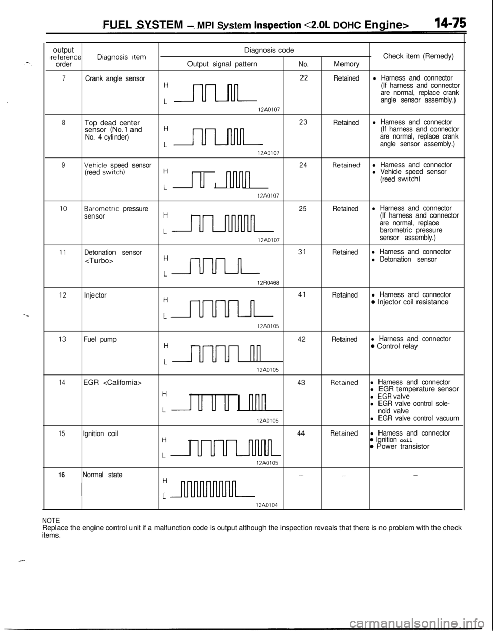
outputDiagnosis codeIreferenceDragnosrs ItemCheck item (Remedy)orderOutput signal patternNo.Memory
7Crank angle sensor
:nn **
Retainedl Harness and connector
(If harness and connector
are normal, replace crank
angle sensor assembly.)
12A0107
8Top dead center
:- 23
Retainedl Harness and connectorsensor (No.1 and(If harness and connector
No. 4 cylinder)are normal, replace crank
angle sensor assembly.)
12A0107
9Vehicle speed sensor24Retainedl Harness and connector
(reed swatch)H
I u I nlvln
l Vehicle speed sensor
(reed switch)
L12A0107
10Barometnc pressure25Retainedl Harness and connector
sensorH(If harness and connector
are normal, replace
LULllnMllbarometric pressure
12A0107sensor assembly.)
11Detonation sensorRetainedl Harness and connector
:m 31
l Detonation sensor
12R0468
12Injector
:m 41
Retainedl Harness and connector0 Injector coil resistance
12A0105
13Fuel pump42Retainedl Harness and connectorH
UUUI nn
0 Control relay
L12A0105
14EGR 43Retainedl Harness and connector
Hl EGR temperature sensor
u u u I nnn
l EGRvalvel EGR valve control sole-Lnoid valve
12A0105l EGR valve control vacuum
15Ignition coil44Retainedl Harness and connectorH
UUUL-llMlL
0 Ignition coil0 Power transistor
L12A0105
16Normal state---H
L
12A0104
NOTEReplace the engine control unit if a malfunction code is output although the inspection reveals that there is no problem with the check
items.
Page 536 of 1216

14-82FUEL SYSTEM - MPI System Inspection <2.0L DOHC Engine>
\ \\I \3FUO352
,\ \
\I \3FUO353
,\ ‘\R/
\ \\I \3FUo354
POWER TRANSISTORRefer to GROUP 8
- Ignition System
NlIAcQAl
a-4
AIR CONDITIONER POWER RELAYN14NCl.a -Refer to GROUP 24
- Air Conditioner.
PURGE CONTROL SOLENOID VALVEN14RCKARefer to GROUP 25
- Evaporative Emission Control System.
EGR CONTROL SOLENOID VALVE
N14NCURefer to GROUP 25
- Exhaust Gas Recirculation System.
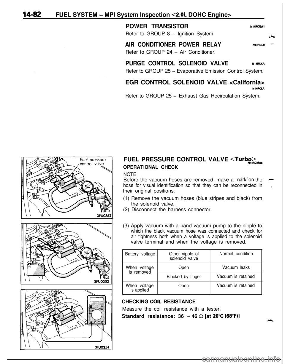
FUEL PRESSURE CONTROL VALVE
OPERATIONAL CHECK
NOTEBefore the vacuum hoses are removed, make a mark’on the
-
hose for visual identification so that they can be reconnected in,their original positions.
(1) Remove the vacuum hoses (blue stripes and black) from
the solenoid valve.
(2) Disconnect the harness connector.
(3) Apply vacuum with a hand vacuum pump to the nipple to
which the black vacuum hose was connected and check for
air tightness both when a voltage is applied to the solenoidvalve terminal and when the voltage is removed.
Battery voltageOther nipple of
solenoid valveNormal condition
When voltage
is removed
When voltage
is applied
OpenVacuum leaks
Blocked by fingerVacuum is retained
OpenVacuum is retainedCHECKING
COIL RESISTANCE
Measure the coil resistance with a tester.
Standard resistance: 36
- 46 R [at 20°C (68”F)]