Page 278 of 1216
7-30COOLING - waterHose and Water Piue <2.0L DOHC Ermine (Non-Turbo)>
04ROO24
04AOO98SERVICE POINTS OF INSTALLATION
N071DAJZ
17. INSTALLATION OF O-RING/ 16. WATER INLET PIPE“4Insert the O-ring to the water inlet pipe, and coat the outer
circumference of the O-ring with water.
By coating with water, the insertion to the water pump will
become easier.Caution
Care must be taken not to permit engine oil or other
greases to adhere to the O-ring
15. CONNECTION OF RADIATOR LOWER HOSEAlign the mating marks on the radiator hose and hose
clamp and then connect them; then, applying force in the
direction indicated by the arrow in the illustration, seat the
clamp to the trace marks of the previous connection.Caution
Be sure to install the hose clamps at the trace marks ofthe
previous connection.
Page 280 of 1216
7-32COOLING -Water Hose and Water Pipe <2.0L DOHC Engine (Turbo)>
35-50 Nm/ 25-36 ft.lbs.
35-50 Nm-- - _ . __._25-36 ft.lbs.25. Oil return pipe
26.Gasket
++ l 27. Turbocharger
28.Eye bolt29.Gasket
30.Water pipe631.Eye bolt32.Gasket33. Water pipe A
++ 34. Water hose (to turbocharger)35. Water hose
36. Water by-pass hose37. Connection for heater hose
+e l 38. Connection for radiator lower hose39. Water hose
40. Water hose
41. Water hose
22-30 ft.lbs.30-40 Nm
22-29 ft.lbs.04A011642. Exhaust pipe support bracket
43. Water pipe
l * 44. Water inlet pipe
l * 45. O-ring
FFTkeverse the removal procedures to reinstall.(2) a+ : Refer to “Service Points of Removal”.(3) l + : Refer to “Service Points of Installation”(4) m : Non-reusable parts
Page 281 of 1216

COOLING- Water Hose and Water Pipe <2.0L DOHC Engine (Turbo)>7-330140552
Mating marks
04A0090
rMating marks
04A0090
SERVICE POINTS OF REMOVALNO7lBAC311. DISCONNECTION OF POWER STEERING OIL PUMP
Disconnect the oil pump with hoses from the bracket.
NOTEThe removed power steering oil pump should be fastened
(by using rope, etc.) in a position that will not interfere with
the removal/installation of the engine assembly.
27. REMOVAL OF TURBOCHARGER ASSEMBLY
Remove the turbocharger assembly with the exhaust
fitting, water pipe A, water pipe
B and the oil pipe attached
to it.
38. DISCONNECTION OF RADIATOR LOWER HOSE
After making mating marks on the radiator hose and the
hose clamp, disconnect the radiator hose.
INSPECTIONN07lCAAa3WATER PIPE AND HOSE INSPECTION
Check the water pipe and hose for cracks, damage, clog and
replace them if necessary.
SERVICE POINTS OF INSTALLATION
N071DAJ345. INSTALLATION OF
0-RING/44. WATER INLET PIPE
Insert the O-ring to the water inlet pipe, and coat the outer
circumference of the O-ring with water.
By coating with water, the insertion to the water pump will
become easier.
Caution
Care must be taken not to permit engine oil or other
greases to adhere to the O-ring.
38. CONNECTION OF RADIATOR LOWER HOSE
Align the mating marks on the radiator hose and hose
clamp and then connect them; then, applying force in the
direction indicated by the arrow in the illustration, seat the
clamp to the trace marks of the previous connection.
Caution
Be sure to install the hose clamps at the trace marks ofthe previous connection.
Page 315 of 1216

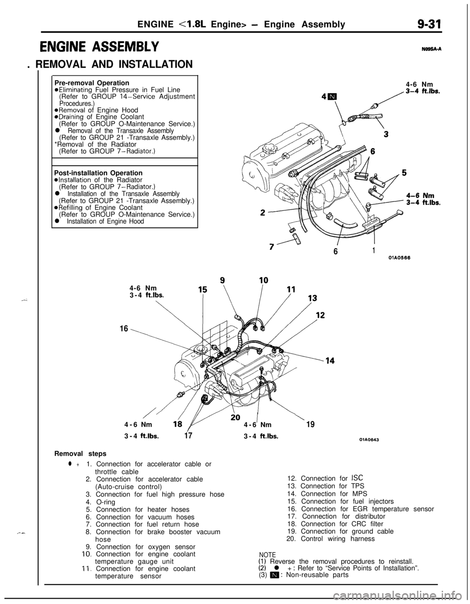
ENGINE <1.8L Engine> - Engine Assembly9-31
ENGINE ASSEMBLY
. REMOVAL AND INSTALLATION
N69SA-APre-removal Operation
@Eliminating Fuel Pressure in Fuel Line
(Refer to GROUP 14-Service AdjustmentProcedures.)@Removal of Engine HoodeDraining of Engine Coolant
(Refer to GROUP O-Maintenance Service.)
l Removal of the Transaxle Assembly(Refer to GROUP 21 -Transaxle Assembly.)
*Removal of the Radiator
(Refer to GROUP 7-Radiator.)
Post-installation Operation
@Installation of the Radiator
(Refer to GROUP 7-Radiator.)
l Installation of the Transaxle Assembly(Refer to GROUP 21 -Transaxle Assembly.)
@Refilling of Engine Coolant
(Refer to GROUP O-Maintenance Service.)
l Installation of Engine Hood4-6 Nm
“7
/61OlA05664-6 Nm
3-4
ft.lbs.
\
16
/io1\4-6Nm164-6Nm193-4ft.lbs.
173-4ft.lbs.OlA0643Removal steps
l +1. Connection for accelerator cable or
throttle cable
2. Connection for accelerator cable
(Auto-cruise control)
3. Connection for fuel high pressure hose
4. O-ring
5. Connection for heater hoses
6. Connection for vacuum hoses
7. Connection for fuel return hose
8. Connection for brake booster vacuum
hose
9. Connection for oxygen sensor
10. Connection for engine coolant
temperature gauge unit
11. Connection for engine coolant
temperature sensor12. Connection for
ISC13. Connection for TPS
14. Connection for MPS
15. Connection for fuel injectors
16. Connection for EGR temperature sensor
17. Connection for distributor
18. Connection for CRC filter
19. Connection for ground cable
20. Control wiring harness
NOTE(1) Reverse the removal procedures to reinstall.(2) l + : Refer to “Service Points of Installation”.
(3) m : Non-reusable parts
Page 320 of 1216

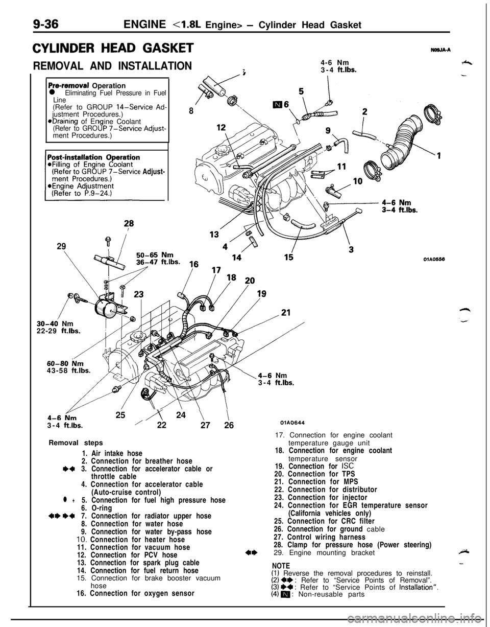
9-36ENGINE - Cylinder Head Gasket
CYLINDER HEAD GASKET
REMOVAL AND INSTALLATION4-6 Nm
73-4 ft.lbs.
NWJA-A
Pre-removal Operationl Eliminating Fuel Pressure in Fuel
Line(Refer to GROUP
14-Service Ad-
justment Procedures.)*Draining of En
ine Coolant
(Refer to GRO9P -/-Service Adjust-ment Procedures.)
(Refer to GROUP
7-Service Adjust-~~~~~~~n
?*
29?i
8
30-46 Nm
22-29 ft.lbs.
60-80 ium43-58 ftlbs.25
iy 24 \\3-4
ftlbs./2227 26
Removal steps
1. Air intake hose
2. Connection for breather hose
I)43. Connection for accelerator cable or
throttle cable
4. Connection for accelerator cable
(Auto-cruise control)
l +5. Connection for fuel high pressure hose
6. O-ring
+e W7. Connection for radiator upper hose
8. Connection for water hose
9. Connection for water by-pass hose
10. Connection for heater hose
11. Connection for vacuum hose
12. Connection for PCV hose
13. Connection for spark plug cable
14. Connection for fuel return hose
15. Connection for brake booster vacuum
hose
16. Connection for oxygen sensor
1\4-6 Nm
3-4 ftlbs.
OlAO556
QlAO64417. Connection for engine coolant
temperature gauge unit
18. Connection for engine coolant
temperature sensor
19. Connection for
ISC20. Connection for TPS
21. Connection for MPS
22. Connection for distributor
23. Connection for injector
24. Connection for EGR temperature sensor
(California vehicles only)
25. Connection for CRC filter
26. Connection for ground cable
27. Control wiring harness
28. Clamp for pressure hose (Power steering)
29. Engine mounting bracket
NOTE
(I) Reverse the removal procedures to reinstall.(2) Ce : Refer to “Service Points of Removal”.(3) ++ : Refer to “Service Points of Installation”.(4) m : Non-reusable parts
Page 322 of 1216
9-38ENGINE <1.8L Engine> - Cylinder Head Gasket
04UOO27Timing mark
\Timing mark
OlR0153
SERVICE POINTS OF REMOVALNWJSAO7. REMOVAL OF RADIATOR UPPER HOSE
,zMake mating marks on the radiator hose and hose clamp,
b-and then disconnect the radiator hose.
29. REMOVAL OF ENGINE MOUNTING BRACKET
(1) Jack up the vehicle after placing a wooden block
between the jack and the engine’s oil pan.
CautionJack up carefully, so as not to apply an excessive
load to the various parts.
(2) Remove the engine mount bracket.
33. REMOVAL OF CAMSHAFT SPROCKET
(1) Turn the crankshaft clockwise and align the timing
mark.Caution
rzThe crankshaft must always be rotated in the
-’clockwise only.
(2) Remove the camshaft sprocket (with the timing belt
attached), and place on the timing belt front lower
cover.Caution
After removing the camshaft sprocket, be sure not
to rotate the crankshaft.
R
Page 324 of 1216

ENGINE <1.8L Engine> - Cylinder Head Gasket
OlAOlO:Intake sideFront of engine
I,Exhaust side
01R0390
4pply
sealant 1Mating marks
.,
iighDelivery pipe3ressureloseO-ring03Aoo79(2) Using the special tool, tighten the bolts in the
ordershown in two or three steps.
a-2
31. APPLICATION OF SEALANT TO SEMI-CIRCULAR PACK-ING
Apply a coating of the specified sealant to the semi-circularpacking and the cylinder head top surfaces.
/LSpecified sealant: MOPAR Part No.4318034 or equiva-
_ ‘-lent
7.INSTALLATION OF RADIATOR UPPER HOSE
Align the mating marks (of the radiator hose and hose
clamp), and then, while applying force in the direction of
the arrow in the illustration, set the hose clamp to the
trace marks (on the hose) remaining from the prior
connection.
Caution
Be sure to install the hose clamp at the trace marks (onthe hose) remaining from the prior connection.
5. CONNECTION OF FUEL HIGH PRESSURE HOSE
When connecting the fuel high-pressure hose to the
delivery pipe, apply a coating of gasoline to the hose union,and insert so that the O-ring is not damaged.
3. INSTALLATION OF ACCELERATOR CABLE OR
THROT- +TLE CABLE CONNECTION
Refer to GROUP
14-Service Adjustment Procedures.
Page 365 of 1216

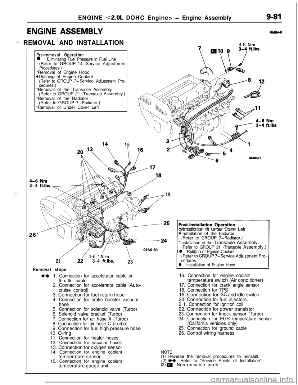
ENGINE <2.0L DOHC Engine> - Engine Assembly
ENGINE ASSEMBLY
- REMOVAL AND INSTALLATION
;-
Pre-removal Operationl Eliminating Fuel Pressure in Fuel Line(Refer to GROUP 14-Service AdjustmentProcedures.)*Removal of Engine Hood
@Draining of Engine Coolant(Refer to GROUP 7-Service Adjustment Pro-
cedures.)*Removal of the Transaxle Assembly
(Refer to GROUP 21 -Transaxle Assembly.)
*Removal of the Radiator
(Refer to GROUP 7-Radiator.)
*Removal of Under Cover Left
26'
15
I4-6 Nm\I /MAO571
19@Installation of Under Cover Left
*Installation of the Transaxle Assembly
(Refer to GROUP 21 -Transaxle Assembly.)
I l Refilling of Enaine Coolant
/22/ 4-6 ‘Nm\213-4 ftlbs.23
Removal steps
~~1. Connection for accelerator cable orthrottle cable
2. Connection for accelerator cable (Auto-
cruise control)3. Connection for fuel return hose
4. Connection for brake booster vacuum
hose
5. Connection for solenoid valve (Turbo)
6. Solenoid valve bracket (Turbo)
7. Connection for air hose A (Turbo)
8. Connection for air hose
C (Turbo)9. Connection for fuel high pressure hose
10. O-ring11. Connection for heater hoses12. Connection for vacuum hoses
13. Connection for oxygen sensor
14. Connection for engine coolant
temperature sensor
15. Connection for engine coolant
temperature gauge unit(Refer
t’o GROUP 7-Service Adjustment Pro-cedures.)l Installation of Engine Hood‘I
16. Connection for engine coolanttemperature switch (Air conditioner)
17. Connection for crank angle sensor
18. Connection for TPS19. Connection for
ISC and idle switch
20. Connection for fuel injectors
2 1. Connection for ignition coil22. Connection for power transistor
23. Connection for knock sensor (Turbo)
24. Connection for EGR temperature sensor
(California vehicles only)
25. Connection for ground cable26. Control wiring harness
NOTE(I) Reverse the removal procedures to reinstall.
(2) e+ : Refer to “Service Points of Installation”.(3) m : Non-reusable parts