1991 MITSUBISHI 3000GT oil type
[x] Cancel search: oil typePage 724 of 1146

35-2SERVICE BRAKES - Specifications
SPECIFICATIONSrvKwx.- -
GENERAL SPECIFICATIONSItems
FWDAWD
Master cylinderTypeTandem type
(with level sensor)Tandem type
(with level sensor)
I.D. mm (in.)
25.4
(1) or 26.9 (1 %s)*26.9 (1 '/l6)Brake boosterTypeVacuum type, tandemVacuum type, tandem
Effective dia. of power cylinder
mm (in.)
180 (7.0) + 205 (8.0) or203 (8.0) + 230 (9.0)
203 (8.0) + 230 (9.0)”
Boosting ratio
6.0 [at 247 N (54
Ibs.)] or7.0
[Brake pedal depressing force]
7.0 [at 261 N (58 Ibs.)]”[at 261 N (58 Ibs.)]Proportioning valve
Split point
MPa (psi)3.75 - 4.25 (533 - 604)3.75 - 4.25 (533 - 604)
Decompression ratio
0.370.37
Front brakesTypeFloating caliper, 2-piston,Rigid caliper, 4-piston,
ventilated disc (M-R57W)ventilated disc
(M-R66Z)Disc effective dia.mm (in.)
227
(9.0)249 (9.8)Disc thickness
mm (in.)24
(.94)30 (1.18)
Pad thicknessmm (in.)
16 (.63)15 l.59)
Wheel cylinder I.D.mm (in.)
42.8(1"/16)X240.4(1'g/32)x2 +42.8(1"/16)~2
Clearance adjustment
AutomaticAutomatic
Rear brakesTypeFloating caliper, l-piston,
ventilated disc
(M-R45V)Floating caliper, 1 -piston,
ventilated disc (M-R58V)Disc effective dia.mm (in.)
228
(9.0)237 (9.4)Disc thicknessmm (in.)
18 (.71)20 (.79)Pad thickness
mm (in.)15.5
(.61)15.5 (.61)Wheel cylinder I.D.mm (in.)
34.9 (13/8)38.1 (1%)
Clearance adjustmentAutomaticAutomatic
Rotor teeth
Front wheel side
4747Rear wheel side
4747Speed sensor
Magnet coil typeMagnet coil type
NOTE*:ABS
TSB Revision
Page 830 of 1146

37A-2SPECIFICATIONS
STEERING - Specifications
GENERAL SPECIFICATIONS
M37CA-A
LA,Items
Steering wheel
Steering wheel O.D.
mm (in.)
Gear box
Steering gear type
Power steering oil pump
Oil pump type
Displacementcm3/rev. (cu.in./rev.)
Relief set pressureMPa (psi)
Specifications
390 (15.4)
Rack and pinion
Vane type
9.6 t.59)
8(1,138)
SERVICE SPECIFICATIONSM37CB-A
!msSpecifications
andard value
Steering wheel free play (with engine stopped)
mm (in.)11 (43)
Steering angle
Inner wheel33”45’ 2 2”
Outer wheel28”21’
Tie rod end ball joint starting torqueNm (in.lbs.)
FWD0.5 - 3.0 (4 - 26)
AWDl.O-3.0(9-26)
Stationary steering effortN (Ibs.)35 (8) or less
V-belt deflectionmm (in.)
When belt tension is inspected or readjusted9-11 (.35-.43)
When new belt is installed7 - 8.5 (.28 - .33)
Oil pump pressureMPa (psi)
Pressure gauge valve closed7.5-8.2 (1,067- 1,166)
Pressure gauge valve opened0.8-1.0(114-142)
Oil pressure switch operating pressureMPa (psi)
Oil pressure switch contacts closed (continuity)
1.5-2.0(213-284)
Oil pressure switch contacts opened (no continuity)0.7-1.2(100-171)
Total pinion torqueNm (in.lbs.)0.6-1.3(5-11)
Tie-rod joint swing resistanceN (Ibs.)8-18(1.8-4.0)
Tie-rod joint swing torqueNm (in.lbs.)2-5(17-43)nit
Steering wheel free play (when hydraulic operation)mm (in.) 30 (1.2)
Variation of tie rod end ball joint shaft direction
mm (in.)1.5 i.059)
Oil pump pressure
Pressure gauge valve opened
MPa (psi)1.5 (213)
Space between vane and rotormm (in.)0.06 (0024)
LJ’
I
I
L’l
1 TSB Revision
Page 862 of 1146

37B-24-WHEEL STEERING SYSTEM (4WS) -Specifications / Special Tools
SPECIFICATIONS
GENERAL SPECIFICATIONSM37CA-B
Items
Power steering gear box
Type
Oil pump
Type
Displacement
cm”/rev. (cu.in./rev.)
Relief set pressure
MPa (psi)
Rear oil pump
Type
Displacement
cm’/rev. (cu.in./rev.)
Relief set pressure
MPa (psi)
Power cylinder
Type
Strokemm (in.)
Specifications
Rack and pinion
Vane type
9.6 (0.59)
8 (1,138)
Vane type
3.3 (0.20)
4 (569)
Hydraulic double action type
20 i.78) [one side 10 (.39)1
SERVICE SPECIFICATIONSM37CEB
Items
Standard value
Specifications
Rear oil pump displacement [at speedometer reading of
31 mph (50 km/h) for 30 seconds]liter (qts.)
Power cylinder ball joint rotation starting torqueNm (in.lbs.)
Power cylinder tie rod swing torqueN (Ibs.) [Nm (in.lbs.)]
Power cylinder slide resistanceN (Ibs.)
Approx. 1 .O (1.06)
0.5 (4) or less
9 - 55 (2 - 12) IO.5 - 3.0 (4 - 26)l
67 (15) or less
LUBRICANTSM37CD.B
,II
Items
Power steering fluid
Dust cover
Specified lubricant
MITSUBISHI PLUS
ATFiAutomatic Trans-mission fluid “DEXRON” or “DEXRON II”
‘Silicone grease
Quantity
1.45 liter (1.53 qts.)
As requiredSPECIAL TOOLS
M37DA-6
MB990993-01Power steering oilpressure gauge
Measurement of fluid flow volumeTSB Revision
Page 863 of 1146

4-WHEEL STEERING SYSTEM (4WS) - Troubleshooting
TROUBLESHOOTING
37B-3
M37EMKBefore inspecting, check the following items:
l Oil pump drive belt tension
lEnsure that the suspension has not been mod-@Power steering fluid level, and air in the system
ified
l Engine
Idle soeed and even idle
lTire and wheel size, specifications, air pressure,
l Oil leakage
balance and amount of wear
l Steering wheel type
l Wheel alignment
Malfunction symptom
4WS does not operateMalfunctioning system
Power cylinderInspection item
Tie rod swing torque
Power cylinder slide resistance
Rear oil pump
Flow volume check
Control valve
-
Poor steering feelingSteering gears and linkage
Rack cracks or deformationFeeling of friction in steering
Poor steering return
Steering wheel efforts
excessive
Control valve
Oil leakage from control valve jornt
Rear wheels cannot be
steered
Poor rear wheels return
Hydraulic pressure for rear
wheel is constantly high
Long rear wheel steering
delayPoor steering response
Poor steering returnPower cylinder
Oil lineOil reservoir
Control valve
Power cylinder
Rear oil pump
Power cylinder
Oil leakage from piston rod
Pressure hose breakage
Oil reservoir deformation or oil leakage
Stuck control valve spool
Stuck power cylinder
Relief valve remains open
Excessive power cylinder friction-
Looseness in power cylinder tie rod ball jo.int
Ball joint dust cover cracks
Poor rear wheel steeringresponsePoor rear wheel steeringrange
Poor steerability (extremetire wear)Control valve
Power cylinder
Rear oil pump
Power cylinder
Oil leakage from control valve spool
Oil leakage from power cylinder
Extreme oil pump internal wear
Tie rod length improperly adjusted after toe-inadjustment
[ TSB Revision
Page 874 of 1146

42-2BODY - SDecifications
SPECIFICATIONS
GENERAL SPECIFICATIONS
M42CA. -
Items
Hood
Type
Specifications
Rear hinged, front
opening type (with gas damper)
Door
Construction
Regulator system
Locking system
Liftgate
Type
Front-hinged, sashless
Wire type
Pin-fork type
Inner-hinged, with gas damper
Glass installation method
Windshield glassAdhesive type
Quarter window glassAdhesive type
Liftgate window glassAdhesive type
Glass thicknessmm (in.)
Windshield glass5.3 (.21)
Liftgate window glass3.5 (.I41
Door glass5.0 f.20)
Quarter window glass3.5 (.14)
Power window motor
TypePermanent magnet type (Built-in circuit breaker)
Revolutions under no load
rpm75 or more
Revolutions under load
vm
At 1 Nm (.72 ft.lbs.145-75
At 2 Nm (1.45 ft.lbs.)50-80
Bound current A
34 or less
Direction of rotationClockwise and counter-clockwise
Power window main switch
TypeAutomatic reset type
Rated load currentA
Lock switch
10Power window switch
10
Power window sub switch
TypeAutomatic reset type
Rated load currentA10
Power window relay
Maximum contact current
A20
Rated coil current
AMax. 0.2
Voltage drop between terminals
V0.2 or less
(At 12 V and the rated load current)TSB Revision
Page 1091 of 1146

HEATERS AND MANUAL AIR CONDITIONER - safety Pre=utm55-9
SAFETY PRECAUTIONSR-12 refrigerant is a chlorofluoro-carbon
(CFC) that
can contribute to the depletion of the ozone layer in
the upper atmosphere.
Ozone filters out harmful radiation from the sun.
To assist in protecting the ozone layer, Mitsubishi
Motor Sales of America recommends that a R-12
refrigerant recycling device that meets SAE stan-
dard
J1991 be used.
Contact an automotive service equipment supplier
for refrigerant recycling equipment that is available
in your area.
The refrigerant used in all air conditioner is R-l 2. It is
transparent and colorless in both the liquid and
vapor state. Since it has a boiling point of
-29.8”C(-21.7”F), at atmospheric pressure, it will be a vapor
at all normal temperatures and pressures. The vapor
is heavier than air, non-flammable, and nonexplo-
sive. It is nonpoisonous except when it is in direct
contact with open flame. It is noncorrosive except
when combined with water. The following precau-
tions must be observed when handling R-12.
CautionWear safety goggles when servicing the refri-
geration system.R-12 evaporates so rapidly at normal atmospheric
pressures and temperatures that it tends to freeze
anything it contacts. For this reason, extreme care
must be taken to prevent any liquid refrigerant from
contacting the skin and especially the eyes. Always
wear safety goggles when servicing the refrigera-
tion part of the air conditioning system. Keep a
bottle of sterile mineral oil handy when working on
the refrigeration system. Should any liquid re-
frigerant get into the eyes, use a few drops of
mineral oil to wash them out. R-12 is rapidly
absorbed by the oil. Next splash the eyes with
plenty of cold water. Call your doctor immediately
even though irritation has ceased after treatment.
CautionDo not heat R-12 above 52°C
(125.6”F).
M55PAAFIn most instances, moderate heat is required to
bring the pressure of the refrigerant in its container
above the pressure of the system when charging or
adding refrigerant. A bucket or large pan of hot
water not over 52°C
(125.6”F) is all the heat required
for this purpose. Do not heat the refrigerant contain-
er with a blow torch or any other means that would
raise temperature and pressure above this tempera-
ture. Do not weld or steam clean on or near the
system components or refrigerant lines.
Caution
Keep R-12 containers upright when charging the
system.When metering R-12 into the refrigeration system,
keep the supply tank or cans in an upright position. If
the refrigerant container is on its side or upside
down, liquid refrigerant will enter the system and
damage the compressor.
CautionAlways work in a well-ventilated room.
Good ventilation is vital in the working area.
Although R-12 vapor is normally nonpoisonous,
contact with an open flame can cause the vapor to
become very poisonous. A poisonous gas is pro-
duced when using the flame-type leak detector.
Avoid inhaling the fumes from the leak detector.
CautionDo not allow liquid refrigerant to touch bright
metal.Refrigerant will tarnish bright metal and chrome
surfaces, and in combination with moisture can
severely corrode all metal surfaces.
1 TSB Revision
Page 1121 of 1146

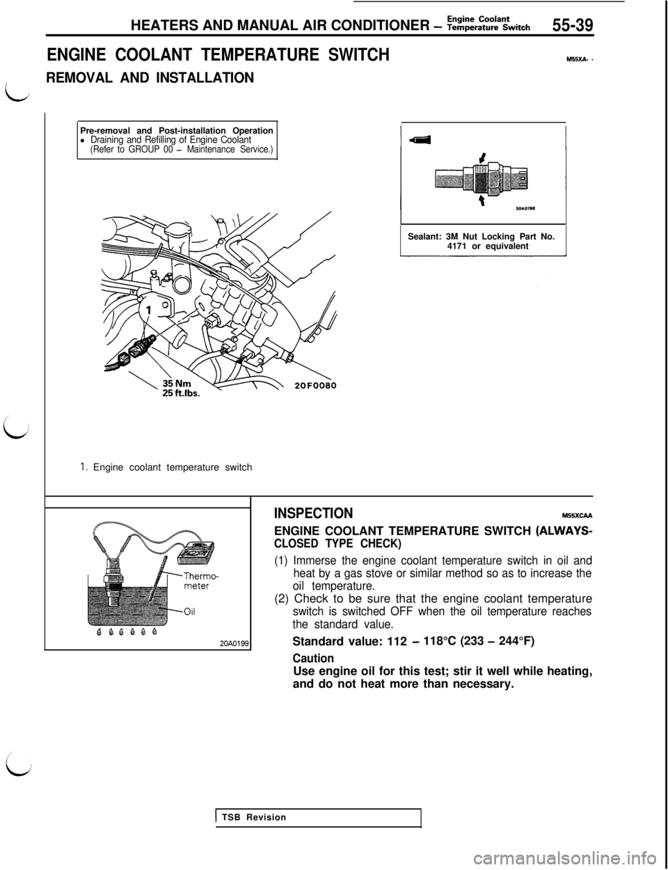
Pre-removal and Post-installation Operationl Draining and Refilling of Engine Coolant(Refer to GROUP 00 - Maintenance Service.)
1. Engine coolant temperature switchHEATERS AND MANUAL AIR CONDITIONER
- Z!&E%Ltch55-39
ENGINE COOLANT TEMPERATURE SWITCH
M55xA- -
L
REMOVAL AND INSTALLATIONSealant: 3M Nut Locking Part No.
4171 or equivalent
BQQQQQ20A0199INSPECTION
MSSXCAAENGINE COOLANT TEMPERATURE SWITCH
(ALWAYS-
CLOSED TYPE CHECK)
(1) Immerse the engine coolant temperature switch in oil and
heat by a gas stove or similar method so as to increase the
oil temperature.(2) Check to be sure that the engine coolant temperature
switch is switched OFF when the oil temperature reaches
the standard value.Standard value: 112
- 118°C (233 - 244°F)
CautionUse engine oil for this test; stir it well while heating,
and do not heat more than necessary.
1 TSB Revision