Page 216 of 1146

13-110FUEL SYSTEM - On-vehicle Inspection of MPI Components
IDLE SPEED CONTROL SERVO (STEPPER MOTOR TYPE)\
7FUO64;Ball beam
‘9
L PlntleControl relay
@ Harness side
connector
\/1, \,\/“1“3 “4 “6Idle speed
control servo
OSCIIIOOSCIIIOOSClllOosclllomu--
/(a /(IT ),!j /I,, Enginecontrol unit
BPPP
7FUO518Engine control unit connector
7FUO653
OPERATION
lThe intake air volume during idling is controlled by opening ‘or closing the servo valve provided in the air
path that bypasses the throttle valve.’
lThe servo valve is opened or closed by operating the stepper motor in the speed control servo in normal or
reverse direction.
lThe battery power is supplied to the stepper motor through the control relay. As the engine control unit
turns on power transistors in the unit one after another, the stepper motor coil is energized and the motor
rotates in normal or reverse direction.
TROUBLESHOOTING HINTSHint 1:If the stepper motor step increases to 100 to 120 steps or decreases to 0 step, faulty stepper motor
or open circuit in the harness is suspected.
Hint 2: If the idle speed control servo harness and individual part checks have resulted normal but the
stepper motor steps are out of specification, the following faults are suspected.
(I) Poorly adjusted reference idle speed
(2) Deposit on the throttle valve
(3) Air leaking into the intake manifold through gasket gap
(4) Loose EGR valve seat
(5)Poor combustion in the cylinder (faulty ignition plug, ignition coil, injector, low compression
pressure, etc.)
\L.J
1 TSB RevisionI
Page 724 of 1146

35-2SERVICE BRAKES - Specifications
SPECIFICATIONSrvKwx.- -
GENERAL SPECIFICATIONSItems
FWDAWD
Master cylinderTypeTandem type
(with level sensor)Tandem type
(with level sensor)
I.D. mm (in.)
25.4
(1) or 26.9 (1 %s)*26.9 (1 '/l6)Brake boosterTypeVacuum type, tandemVacuum type, tandem
Effective dia. of power cylinder
mm (in.)
180 (7.0) + 205 (8.0) or203 (8.0) + 230 (9.0)
203 (8.0) + 230 (9.0)”
Boosting ratio
6.0 [at 247 N (54
Ibs.)] or7.0
[Brake pedal depressing force]
7.0 [at 261 N (58 Ibs.)]”[at 261 N (58 Ibs.)]Proportioning valve
Split point
MPa (psi)3.75 - 4.25 (533 - 604)3.75 - 4.25 (533 - 604)
Decompression ratio
0.370.37
Front brakesTypeFloating caliper, 2-piston,Rigid caliper, 4-piston,
ventilated disc (M-R57W)ventilated disc
(M-R66Z)Disc effective dia.mm (in.)
227
(9.0)249 (9.8)Disc thickness
mm (in.)24
(.94)30 (1.18)
Pad thicknessmm (in.)
16 (.63)15 l.59)
Wheel cylinder I.D.mm (in.)
42.8(1"/16)X240.4(1'g/32)x2 +42.8(1"/16)~2
Clearance adjustment
AutomaticAutomatic
Rear brakesTypeFloating caliper, l-piston,
ventilated disc
(M-R45V)Floating caliper, 1 -piston,
ventilated disc (M-R58V)Disc effective dia.mm (in.)
228
(9.0)237 (9.4)Disc thicknessmm (in.)
18 (.71)20 (.79)Pad thickness
mm (in.)15.5
(.61)15.5 (.61)Wheel cylinder I.D.mm (in.)
34.9 (13/8)38.1 (1%)
Clearance adjustmentAutomaticAutomatic
Rotor teeth
Front wheel side
4747Rear wheel side
4747Speed sensor
Magnet coil typeMagnet coil type
NOTE*:ABS
TSB Revision
Page 1095 of 1146

HEATERS AND MANUAL AIR CONDITIONER - Service AdWment proceres 55-13. .
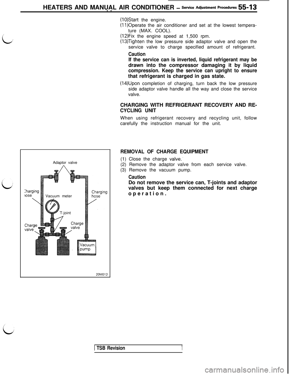
Charginglose
\Adaptor valve
Vacuum meter
T-joint
20M0121
(1O)Start the engine.(1l)Operate the air conditioner and set at the lowest tempera-
ture (MAX. COOL).
(12)Fix the engine speed at 1,500 rpm.
(13)Tighten the low pressure side adaptor valve and open the
service valve to charge specified amount of refrigerant.
Caution
If the service can is inverted, liquid refrigerant may bedrawn into the compressor damaging it by liquid
compression. Keep the service can upright to ensurethat refrigerant is charged in gas state.
(14)Upon completion of charging, turn back the low pressure
side adaptor valve handle all the way and close the service
valve.
CHARGING WITH REFRIGERANT RECOVERY AND RE-
CYCLING UNITWhen using refrigerant recovery and recycling unit, follow
carefully the instruction manual for the unit.
REMOVAL OF CHARGE EQUIPMENT(1) Close the charge
valve:(2) Remove the adaptor valve from each service valve.
(3) Remove the vacuum pump.
CautionDo not remove the service can, T-joints and adaptor
valves but keep them connected for next charge
operation.
1 TSB Revision1