Page 3747 of 4087
OKNG
OKNG
6Check resistance of EGR gas temp. sensor.
C
OK
PDisconnect EGR gas temp. sensor connector
(See page FI±103).
Measure resistance between terminals of EGR gas
temp. sensor connector.
Resistance: 69 ± 89 k � at 50 �C (122 �F)
12 ± 15 k � at 100 �C (212 �F)
2 ± 4 k � at 150 �C (302 �F)
Replace EGR gas temp. sensor.
7Check for open and short in harness and connector between EGR gas temp. sensor and\
engine
& ECT ECU (See IN±27).
Repair or replace harness or connector.
Check and replace engine & ECT ECU.
±
ENGINE TROUBLESHOOTING Circuit InspectionTR±113
WhereEverybodyKnowsYourName
Page 3749 of 4087
DIAGNOSTIC CHART
Check fuel pump operation.
Check for open and short in harness and
connector between check connector and
fuel pump ECU.
Repair or replace harness or connector.
Check voltage of terminal +B of check
connector.
Check for open and short in harness and
connector between check connector and
fuel pump.
Repair or replace harness or connector.
Check voltage of terminal FPC.
Check for open and short in harness and
connector between ECU and fuel pump
ECU. ((FPC)
Check for open and short in harness and
connector between ECU and fuel pump
ECU. (DI)
Check and replace ECU.
Check for ECU power source
circuit.
Repair or replace fuel pump.
Replace fuel pump ECU.
Repair or replace harness or
connector.
Repair or replace harness or
connector.
±
ENGINE TROUBLESHOOTING Circuit InspectionTR±111
WhereEverybodyKnowsYourName
Page 3750 of 4087
OKNG
NGOK
OKNG
INSPECTION PROCEDURE
1Check fuel pump operation.
C
OK
P1. Turn ignition switch ON.
2. Using SST, connect terminals +B and FP of checkconnector.
SST 09843±18020
Check that there is pressure in the hose from the fuel
filter.
Fuel pressure can be felt.
Go to step �.
2Check for open and short in harness and connector between terminals +B e�+B, FP � FP of
the check connector and fuel pump ECU (See page IN±27).
Go to step �.
Repair or replace harness or connector.
3Check voltage of terminal +B of check connector.
C
OK
PTurn ignition switch ON.
Measure voltage between terminal +B of check connec-
tor and body ground.
Voltage: 10 ± 14 V
Check for ECU power source circuit (See page TR±120),
and check for open in harness and connector between
terminal +B of check connector and main relay.
TR±112
±
ENGINE TROUBLESHOOTING Circuit Inspection
WhereEverybodyKnowsYourName
Page 3751 of 4087

NGOK
NGOK
OKNG
OKNG
4Check for open and short in harness and connector between terminal FP of chec\
k connector,
fuel pump and body ground (See page IN±27).
Repair or replace fuel pump.
Repair or replace harness or connector.
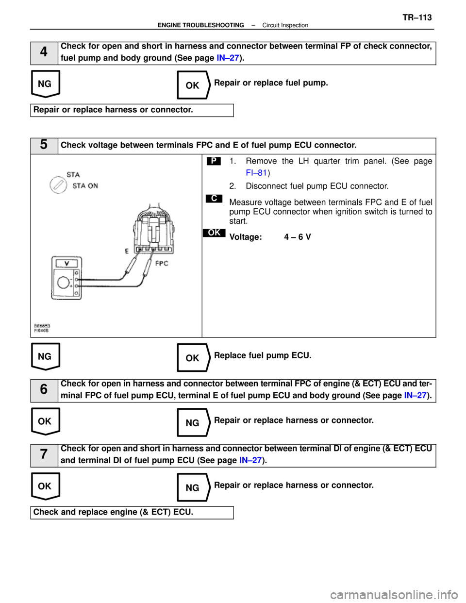
5Check voltage between terminals FPC and E of fuel pump ECU connector.
C
OK
P1. Remove the LH quarter trim panel. (See page FI±81 )
2. Disconnect fuel pump ECU connector.
Measure voltage between terminals FPC and E of fuel
pump ECU connector when ignition switch is turned to
start.
Voltage: 4 ± 6 V
Replace fuel pump ECU.
6Check for open in harness and connector between terminal FPC of engine (& ECT) ECU and ter-
minal FPC of fuel pump ECU, terminal E of fuel pump ECU and body ground (See\
page IN±27).
Repair or replace harness or connector.
7Check for open and short in harness and connector between terminal DI of engin\
e (& ECT) ECU
and terminal DI of fuel pump ECU (See page IN±27).
Repair or replace harness or connector.
Check and replace engine (& ECT) ECU.
±
ENGINE TROUBLESHOOTING Circuit InspectionTR±113
WhereEverybodyKnowsYourName
Page 3753 of 4087
DIAGNOSTIC CHART
DIAGNOSTIC
CHART
Check for open and short in harness and
connector between check connector and fuel
pump.
Check voltage of terminal FPC.Check for open and short in harness and
connector between ECU and fuel pump
ECU. (DI)
Check and replace ECU.
Replace fuel pump ECU.
Repair or replace harness or connector.
Repair or replace harness or
connector.
Check for open and short in harness and
connector between ECU and fuel pump
ECU. (FPC)
Repair or replace harness or
connector.
Repair or replace fuel pump.
Check voltage of terminal +B of check
connector.
Repair or replace harness or connector.
Check for open and short in harness and
connector between check connector and fuel
pump ECU.
Check fuel pump operation.
Check for ECU power source circuit.
±
ENGINE TROUBLESHOOTING Circuit InspectionTR±115
WhereEverybodyKnowsYourName
Page 3754 of 4087
OKNG
NGOK
OKNG
INSPECTION PROCEDURE
1Check fuel pump operation.
C
OK
P(2) Turn ignition switch ON.
(2) Using SST. connect terminals + B and FP of checkconnector.
SST 09843±18020
Check that there is projection of the head of the pulsa-
tion damper screw.
Projection of the head of the pulsation damper
screw.
Go to step 3.
2Check for open and short in harness and connector between terminals + B e + B FP e FP of
the check connector and fuel pump ECU (See page IN±27).
Go to step 5.
Repair or replace harness or connector.
3Check voltage or terminal + B of check connector.
C
OK
PTurn ignition switch ON.
Measure voltage between terminal + B of check connec-
tor and body ground.
Voltage: 10 ± 14 V
Check for ECU power source circuit
(See page TR±124), and check for open in harness and
connector between terminal + B of check connector and
main relay.
TR±116
±
ENGINE TROUBLESHOOTING Circuit Inspection
WhereEverybodyKnowsYourName
Page 3755 of 4087

NGOK
NGOK
OKNG
OKNG
4Check for open and short in harness and connector between terminal FP of chec\
k connector,
fuel pump and body ground (See page IN±27).
Repair or replace fuel pump.
Repair or replace harness or connector.
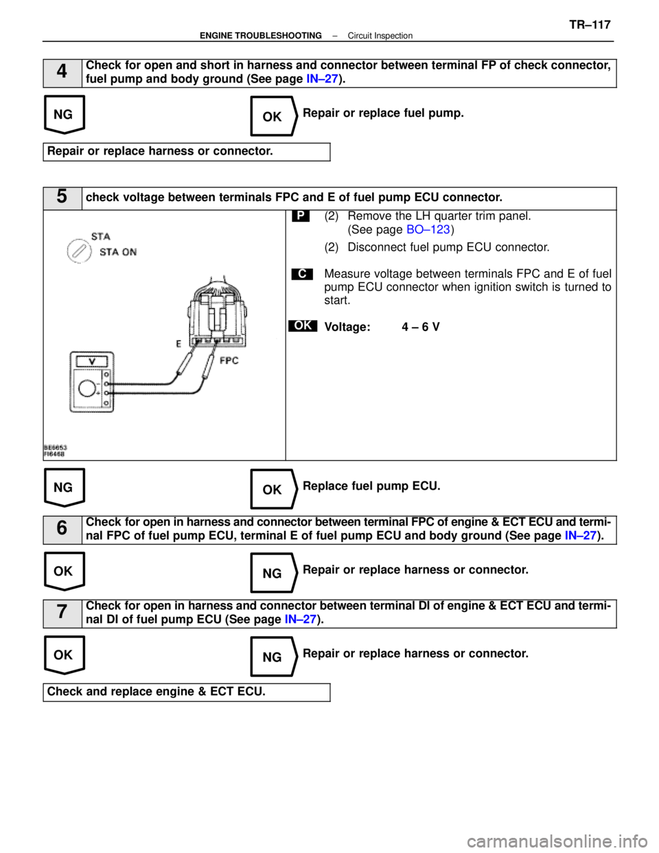
5check voltage between terminals FPC and E of fuel pump ECU connector.
C
OK
P(2) Remove the LH quarter trim panel. (See page BO±123)
(2) Disconnect fuel pump ECU connector.
Measure voltage between terminals FPC and E of fuel
pump ECU connector when ignition switch is turned to
start.
Voltage: 4 ± 6 V
Replace fuel pump ECU.
6Check for open in harness and connector between terminal FPC of engine & ECT ECU a\
nd termi-
nal FPC of fuel pump ECU, terminal E of fuel pump ECU and body ground (See\
page IN±27).
Repair or replace harness or connector.
7Check for open in harness and connector between terminal DI of engine & ECT E\
CU and termi-
nal DI of fuel pump ECU (See page IN±27).
Repair or replace harness or connector.
Check and replace engine & ECT ECU.
±
ENGINE TROUBLESHOOTING Circuit InspectionTR±117
WhereEverybodyKnowsYourName
Page 3757 of 4087
DIAGNOSTIC CHART
DIAGNOSTIC
CHART
NG (NSW)
Check for input signal.
Proceed to next circuit inspection shown
on maxtrix chart (See page TR±35).
Check resistance of throttle
position sensor.
Check input circuit of A/C.
Check and repair harness or connector
between sensor and ECU.
Check for open and short in harness
and connector beteen A/C control assy.
and ECU.
Repair or replace harness or
connector.
Check and replace A/C control
assembly.
Adjust or replace throttle position
sensor (See page FI-73).
See page TR±122.
Check and replace ECU.
±
ENGINE TROUBLESHOOTING Circuit InspectionTR±119
WhereEverybodyKnowsYourName